Need some help with laser setup

Need some help with laser setup
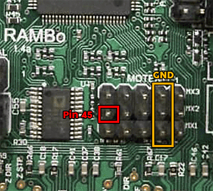
Before I jump down the rabbit hole of the electronics, is there any reason you want to use the 12V fan pin to drive your laser? There are quality issues with using fan pins and M106/M107 to control the laser, and there are better ways for most uses. It looks like you are using a Rambo board. Assuming you are using a later version of V1 maintained, Marlin firmware, laser support is enabled. Pin 45 is the 5V PWM pin used for that support:
In the latest version (115) of the V1 maintained Marlin firmware, you need to insert the following line at the top of your g-code file to enable inline laser commands:
M03 I
Previous versions of the firmware don’t require this line.
On to the fan pins. Most PWM pins work by turning VCC on and off. The fan pins are set up so that the ground connection is turned on and off. On the forum it is referred to as ground-side switching. A high percentage of laser modules, regardless of the voltage, just won’t work with a ground-side switching signal. In order for it to even have a chance of working, your control board and your laser module would need separate power supplies.
If you want to try and use the fan pin, there is a simpler way than a voltage divider circuit. Since the fan pins use ground-side switching, you can pull the power from any 5V pin on the board and just connect the ground connection to the ground pin of the fan connection. The ground connection to the fan ground must be the only ground connection between the two boards.
I was unaware of the M03 I I tried with voltmeter on pin 45 was getting nothing. so I figure I would try and do it the way I did before. Truthfully little intimidated on editing firmware as everything else is working awesome. I tried asking if anyone had the firmware with Laser already enable but did not see any responses. I will test pin 45 with the M03 I now .
Thank you for your time.
GOD Bless
Half Blind Half Crippled Full Crazy Vet
Marvin
Not sure what your problem was with pin 45. If you have a display, you can turn the laser on and off from the display. If you are trying to turn the laser on and off using g-code, be aware that safety timeout was added in version 115, so if your machine does not move for 1s, the pin is shut down. If you need it to be on, and scripted, you can play games with movement to keep it on.
Note that the M03 I is only used for inline commands (laser commands from G0 and G1 parameters). Directly using M3/M5 to turn the laser on and off should work without the M03 I, though the safety timeout still applies.
Note I run my laser from a Rambo board using an unmodified 115 version of the firmware.

I hate bothering people normally beat my head on wall read forum and watch videos until I figure it out… I have spent days doing such to no avail so I am reaching out
Not sure I can get away with the pulling 5V power from else were. The Fan and laser power share the ground with the TTL I assume the laser its self will need the full 12V power
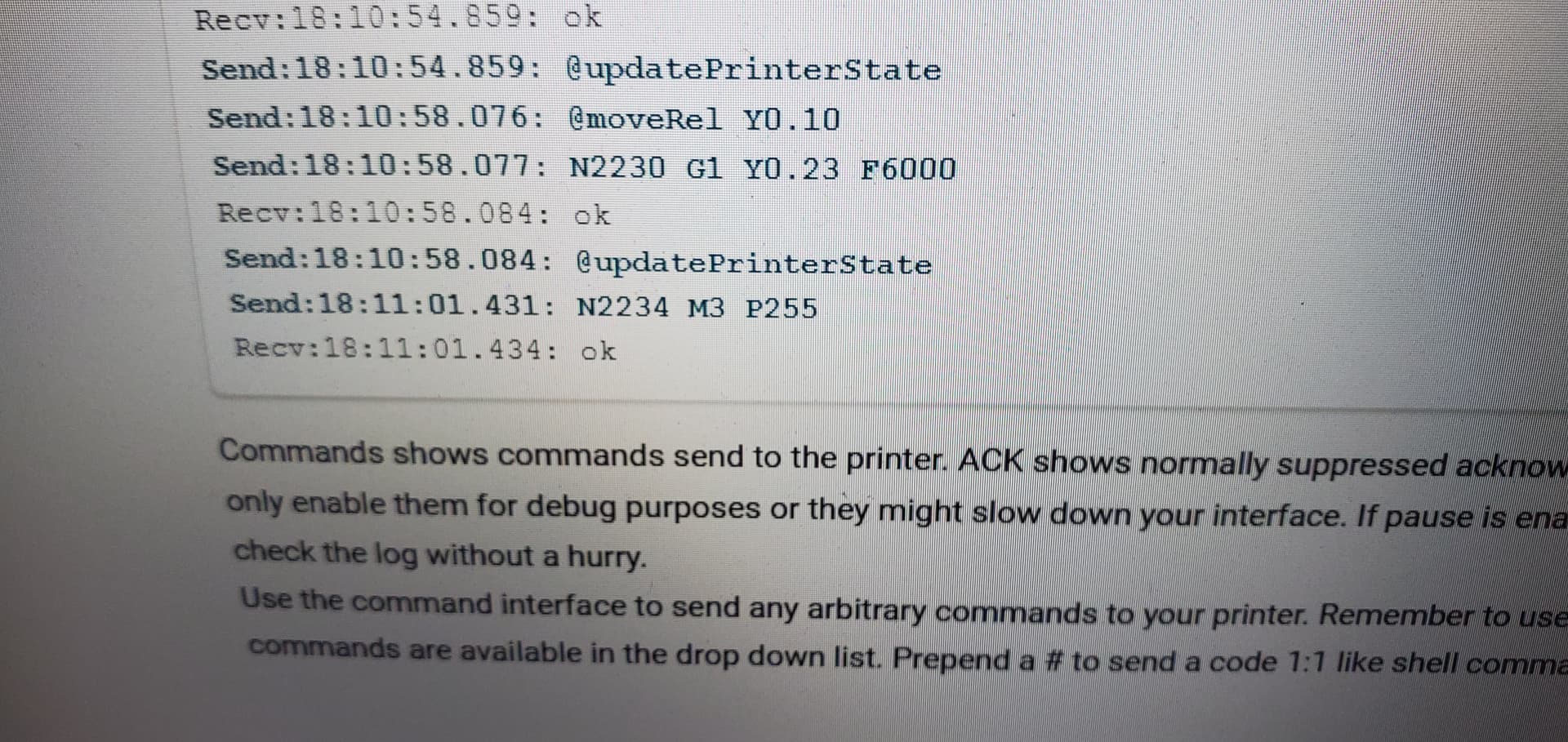
I only have a moment for a reply, but try testing some pins (44, 45, and 46) with M42. M42 is not laser dependent, so you should be able to set the PWM and see the “correct” voltage. This will test the wiring, pins, hookup, etc.
As time permits, I’ll gladly stay with this topic until you get it figured out. Lots of people have used unmodified, V1 firmware and pin 45 to drive their laser, so there is something different in your configuration. And if you happen to figure out the issue, I’d love to know the root of the problem.
LOOKS LIKE ITS WORKING PIN 46 !!!
Using M42 P46 S0 to S255
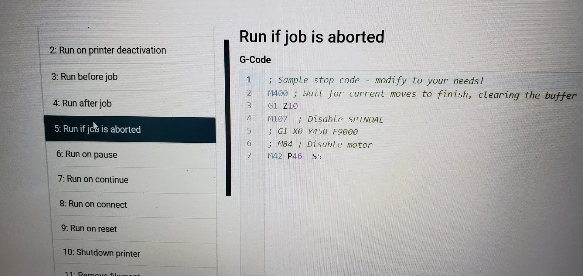
was even able to set some emergency Codes in my REPEATER-SERVER to set laser to M42 P46 S5 on Reset / Pause / Startup just to make sure laser dos not burn anything up on startup or FULL stop command.
Thank you for your Help !!!
I plan on eventually getting new Laser this one is pretty beat up has a lot of hours on it 
If you want your laser to work with the Marlin laser code, you need to either 1) get pin 45 working, or you need to change the pin assigned to the laser to 46. I just tested M42 on my laser pin (45), and it worked, so you should be able to see if you have a bad pin 45. If you need to reassign laser support to pin 46, I can show you where to make the firmware change.
Well tried switching to pin 45 then lost connection to my PI not sure what happend no smoke or sparks but anytime my usb From Rambo is plugged into pi my Repeater server goes down. Tried different USB cable, Unplugged all Laser changes I made, even tried a different PI.
So at this Pont I am thinking my Rambo board is cooked ;(  tomorrow I will try connecting Rambo directly to PC see what happens
Rambo boards are surprising tough, and often survive things that would instantly kill other boards. If you need to change pin 45 to pin 46, let me know and I’ll provide the details.
First I need to trouble shoot the board going to start unplugging things 1 at a time then boot it up and see if the USB issue goes away at this point I seems like it will only run off SD card . And even worse it looks like Ryan is out of Full Rambo boards if it’s fried I may have to get the SK Pro from him sucks my new 1.5KW water cooled SPINDAL will be here Monday and my machine is down. But it may just be bad connection somewhere will go thru it all tommorow
Well I feel stupid !!!
After Completely Dissembling my LR3 and Rambo Board one connection at a time rebooting each time to see if I had a short. Ordering a SKR Pro v1.2 board w/stepper drivers/LCD on amazon because I thought it was fried. Downloaded V1pi ( OCTOPRINT ) and it worked fine conceded via USB … I noticed the BUAD rate on Octoprint was at 250000 went back and looked in connection settings in my Repeater-Server somehow the baud rate had changed to 115200 UGG on the bright side V1PI looks pretty nice it almost looks like the makers of Repeater-Server are using the same system just dressing it up
NOTE TO SELF !!! WHEN IN DOUBT CHECK BAUD RATE
I have new NJE E40 LASER SETUP on pin 45… when I try to cut out something it dos fine if it’s a nice e long outline but center pieces the laser turns off… I tried running light burn bridge on my PI but it looks like it wants a eithernet connection to Rambo board witch of course dos not exist. Not sure what I am doing wrong generating Gcode.
I would love to use light burn I may just have to break down and use a USB cable
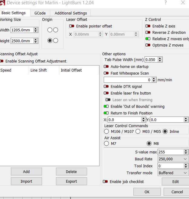
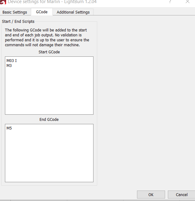
I’m not sure where you are having a problem. Please upload your g-code file, or if it is too big, just the first 100 lines. So, are you running Lightburn off an SD card? If so, I doubt using a USB cable will fix the problem. I run Lightburn files off a SD card using my Rambo board with no issues. Do you have Inline commands selected in Basic Settings?
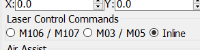
Inline was not enabled I just found the settings I have a PI running connected to my Rambo Its just like octiprint I upload the job to the PI’s web server and run it. I do have the option of using SD may just go that route I just changed to thease settings testing now
; LightBurn 1.2.04
; Marlin device profile, user origin
; Bounds: X590.5 Y1237.98 to X614.5 Y1262.02

;USER START SCRIPT
M03 I
M3
;USER START SCRIPT

G21
G90
G0 X0 Y0 F0
G91
; Cut @ 600 mm/min, 95% power
M9
M05
G0 X5.353 Y3.331 F0
; Layer CUT Pass 1 of 3
G1 X0.022 Y-0.011 F600 I S242.3
G1 X0.804 Y-0.091
G1 X0.789 Y-0.121
G1 X0.222 Y-0.05
G1 X0.22 Y-0.061
G1 X0.548 Y-0.213
G1 X0.531 Y-0.25
G1 X0.512 Y-0.286
G1 X0.491 Y-0.322
G1 X0.407 Y-0.261
G1 X0.411 Y-0.258
G1 X0.094 Y-0.054
G1 X0.375 Y-0.146
G1 X0.388 Y-0.098
G1 X0.397 Y-0.052
G1 X0.529
G1 X0.39 Y0.006
G1 X0.389 Y0.035
G1 X0.237 Y0.038
G1 X0.232 Y0.066
G1 X0.223 Y0.09
G1 X0.212 Y0.115
G1 X0.21 Y0.138
G1 X0.401 Y0.266
G1 X0.401 Y0.265
G1 X0.514 Y0.329
G1 X0.542 Y0.279
G1 X0.565 Y0.226
G1 X0.586 Y0.172
G1 X0.123 Y0.026
G1 X0.196 Y0.036
G1 X0.691 Y0.101
G1 X0.704 Y0.074
G1 X0.015 Y0.008
G1 X0.014 Y0.012
G1 X0.011 Y0.015
G1 X0.007 Y0.018
G1  Y0.019
G1  Y0.015
G1 X-0.01 Y0.022
G1 X-2.355 Y2.27
G1 X-0.123 Y0.139
G1 X-0.104 Y0.153
G1 X-0.015 Y0.024
G1 X-0.3 Y-0.194
G1 X-0.309 Y-0.178
G1 X0.14 Y-0.342
G1 X-0.601 Y-0.247
G1 X0.694 Y-1.686
G1 X-0.409 Y-0.169
G1 X-0.694 Y1.686
G1 X-0.602 Y-0.248
G1 X-0.068 Y0.176
G1 X-0.079 Y0.18
G1 X-0.208 Y-0.053
G1 X-0.271 Y-0.06
G1 X0.14 Y-0.051
G1 X0.125 Y-0.077
G1 X0.107 Y-0.101
G1 X0.086 Y-0.121
G1 X0.06 Y-0.136
G1 X0.032 Y-0.143
G1  Y-0.147
G1 X-0.024 Y-0.146
G1 X-0.028 Y-0.068
G1 X-0.036 Y-0.064
G1 X-0.14 Y-0.139
G1 X-0.166 Y-0.103
G1 X-0.184 Y-0.064
G1 X-0.197 Y-0.023
G1 X-0.353 Y-0.05
G1 X0.115 Y-0.82
G1 X-0.439 Y-0.061
G1 X-0.305 Y2.172
G1 X-0.232
G1 X-0.037 Y-0.374
G1 X-1.176 Y0.138
G1 X-0.057 Y-0.483
G1 X1.094 Y-0.128
G1 X-0.043 Y-0.368
G1 X-1.094 Y0.129
G1 X-0.07 Y-0.593