I’m finally getting my MPCNC back and going and have been doing several “test engraves” for some simple signs. I say “my MPCNC”, and by that I mean the one that Ryan built and brought to MRRF in 2019 :-). It is still mostly in that shape (still haven’t fixed one of the tubes that has a flat spot), other than the DW660 mounts that I added and a spoil board with 1/4" holes centered every 50mm for 300mm in X and Y. I’ve been working on it almost daily for about a month, re-learning the post-processing and upload process, along with what I need to do to properly set the WCS before starting up the spindle.
I’ve been using the pink insulation foam board for the testing (beats ramming the bit into wood) with a light coating of cheap acrylic paint for contrast.
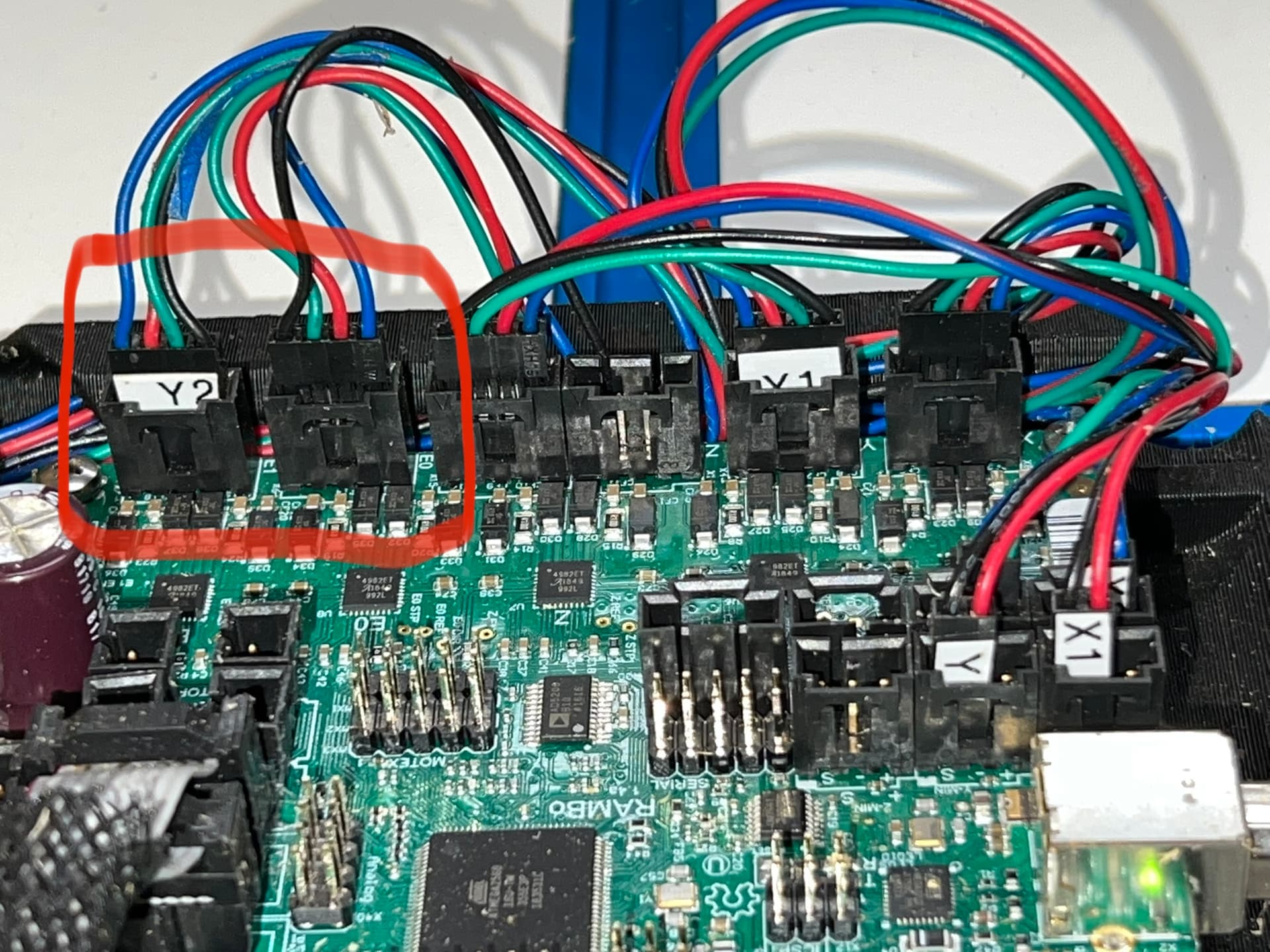
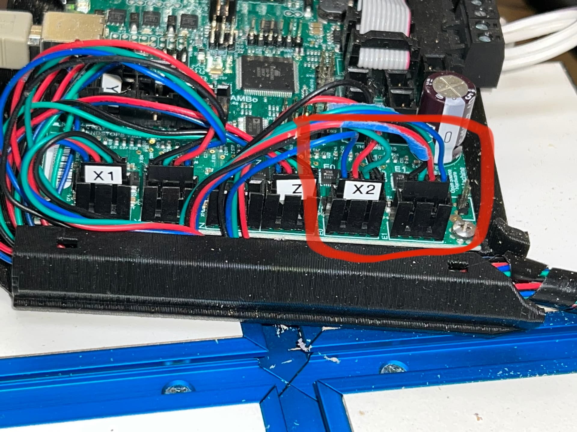
I’ve been having some issues with the setup and last night another retired engineer came over and noticed something very strange. 2 of the stepper motors are NOT being driven at all, 1 on the X and 1 on the Y: specifically the stepper labeled “X2” on the connector and plugged into the E0 connector on the board, and the stepper labeled “Y2” and plugged into the E1 connector on the board. The board is the RAMBo 1.4 board that originally came with the unit. These correspond to the Front X stepper (nearest Y=0mm) and the Right Y stepper (nearest X=300mm).
We further tested these by swapping only the X connections (ONLY done WHEN POWER IS OFF, due to inductor backlash current!!), disconnecting and reconnecting the Octoprint serial connection and then doing a small move using Octoprint’s Control interface on a V1Pi (thanks for v1pi @jeffeb3 – without it I’d be lost). This forces the steppers to be driven. The driven motor switched to the FRONT motor and back motor was not driven. This was checked by trying to twist the shaft of the stepper–the undriven stepper could EASILY be turned, but the driven one stays firm. The direction of movement did reverse as expected (connection was plugged in with the same wire colors in the same positions), since they face in the opposite direction.
We also did this for the Y connections, with an identical result – the driven motor switched positions.
I have also recently re-flashed the firmware on the RAMBo to the latest from the V1 engineering site.
So, from the above it appears to us that the issue is either dead stepper drivers, or a firmware setting that I need to update.
While it is possible the issue is bad stepper drivers, the fact that both X2 and Y2 are not working points strongly to a firmware issue. Usually this is caused by flashing the wrong firmware. You want V1CNC_Rambo_Dual linked on this page. If you have separate wires going to each stepper “Dual” is important, even if you don’t have end stops, and you want to verify by screen or g-code that the right firmware is flashed.
If it turns out to be bad drivers (exceedingly rare for even one to go bad), then you could re-wire your machine to a serial configuration.
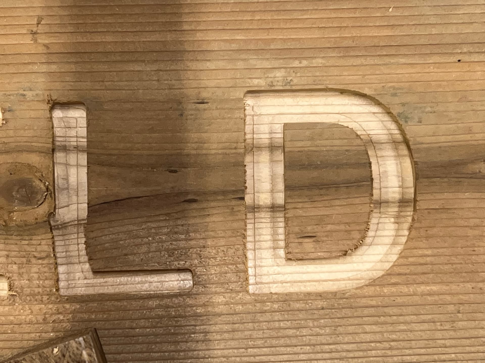
In the image above, the “L” was done with the old, incorrect, single stepper firmware. As you can see there several “angled” lines where there shouldn’t be. Also, the lead-in on the L goes outside the bounding box (just below middle on the left side of the down stroke in the L). Not sure if this is an error in my Fusion 360 Contour Milling operation. I’ll have to re-test (I’m using flyfisher post processor).
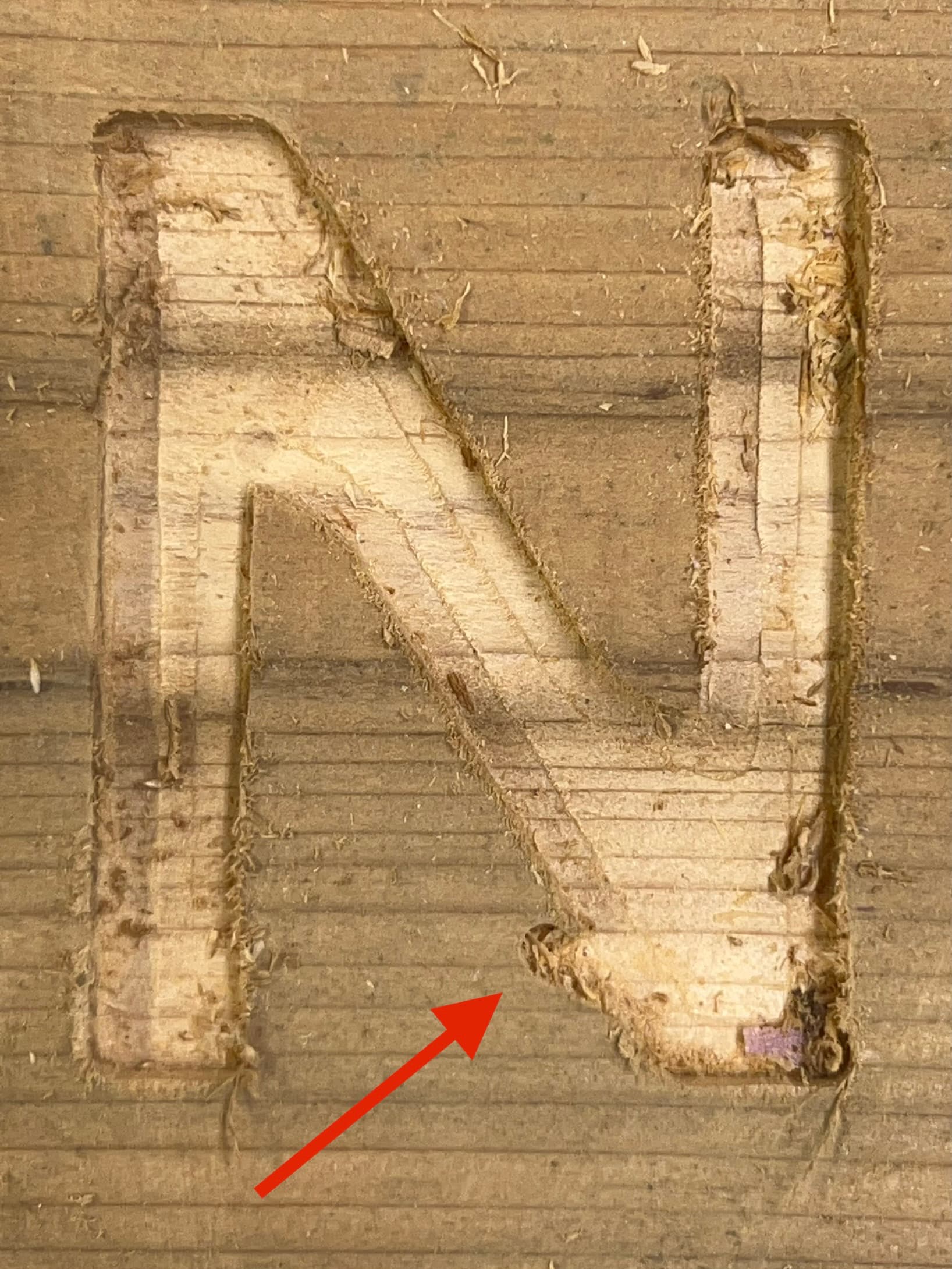
I also have something weird that happened near the end of the 3D Adaptive clearing pass on the letter N. It happened twice, but both times were with the WRONG firmware, so not sure if that’s the issue, or it is something else. Here’s the photo:
As indicated by the arrow, at the end of the adaptive pass, it moves over from the left vertical stroke to finish out the bottom of the right side of the N, and DIVES in outside the bounding box. I did a test in foam before the wood test and it looks almost identical. Could be that the single stepper firmware and the particular set of moves caused the maximum drag/skew of the X-axis bar, as it was a move FAR from the driven stepper and from left to right, so it would make sense that it enters too far to the left, but wow, it’s a lot more than I would expect! More testing required.
Thanks again for you prompt, and correct help!
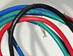
P.S. the weirdness at the wires was a small piece of blue painters tape that had also grabbed some wood chips. I removed it and inspected the wires for any damage–they are perfect–the photo, tape and wood chips just made it look REALLY weird like melted insulation :-). Good eye.