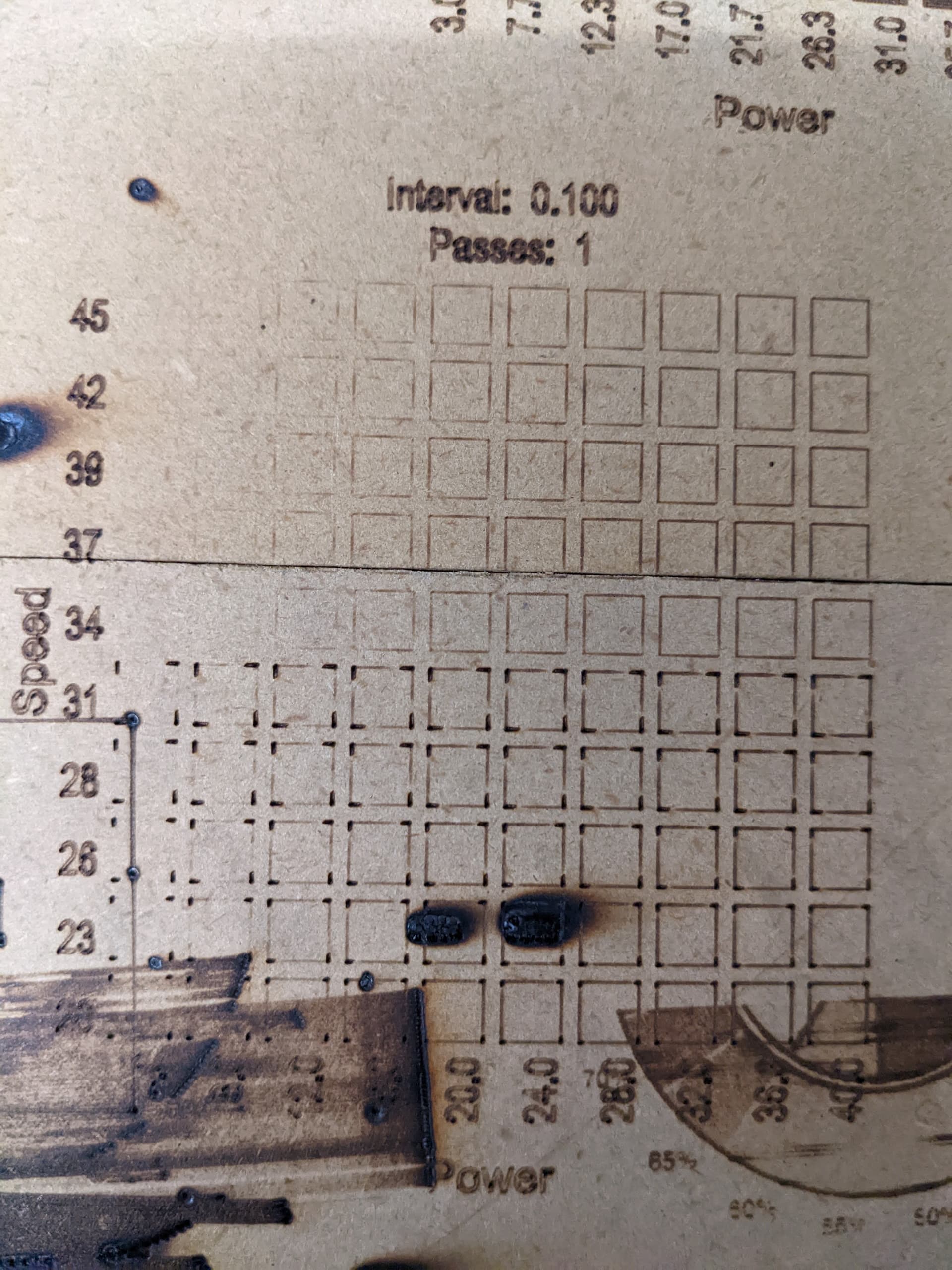
It still looks like 22 mm/s is the max on a rambo, for a raster burn. Not going through all the tests for the SKR since I assume it has not changed either.
New modes were talked about, here, but it seems only “M3 I” works. I tried M3, M4, and M4I, and they do not work to the best of my knowledge.
So the big change is still use inline commands, but your starting Gcode will need to contain M3 I S0 to make it all work, and end with an M5.
The new firmware settings are in the nightlies now, and I will do a new “stable” release pretty soon. Oh and I did not enable M106/7 seems it messes with the other fans as well.
Opinion - vector works well at higher speeds, raster is pretty limited in speed, while it does look amazing. Now is it very slowed when compared to what a GRBL (maybe even RRF?) board can do? For perspective, my 2.5w laser is running at 4.5% min to 28% max to get decent lights and darks (60 shades of gray out of ~254). The CNC’s are both capable of far faster speeds than 22mm/s with only the laser on there, so we are firmware limited.
Looks like it might be time to put serious time into finding a new standard board with some other firmware.
If anyone knows how I might improve these numbers I would love to hear it.
If you want fast, klipper is probably the best bet. Because it removes a lot of the “high level” stuff to the pi, the mcu is just a step cruncher.
I am a little uncertain if that speed translates completely to the laser, since there is also a communication bottleneck, sending a ton of tiny moves, instead of longer ones. But that would be where I would focus.
It is just a little more of a let down this time around. I know how fast we can move these machines now and know the firmware can’t do more is a bummer. Before I get too far ahead of myself I think I need to plug in my GRBL board and see if there is more to be had.
All the tiny moves and power changes must be hard but I tried with no power ramping thinking it would speed things up and it might have only bought 1-2mm/s. There must be a hardware/software limit I can work backwards from so I can box in my expectations.
Interesting conversation and the timing is motivating to me. I just gave a first pass attempt to connect one of my lasers to my Duet 2 WiFi. 5V PWM doesn’t work so well on that hardware. Apparently they fixed the issue with everything Duet 3 and on. But the Duet 2 has some sort of a dirty 5 volt so the laser TTL gets confused if you don’t add a small circuit to clean it up. When I get this figured out I would gladly do any tests to compare benchmarks.
Now I gotta get this working.
That is the part I am just not understanding. With the ramping turned off it is not processing anything, it is just changing the ttl/pwm. No accelerations until the ends when the ttl is not changing. I feel like it should easily handle more, it can’t be processor intensive to change the ttl frequency, can it?
Now for whatever reason it seems when you do use just M3 (not M3 I) accelerations are enabled for the change in laser power so it is a burnt mess.
The programming is still very wrong. I mean M4I doesn’t work, and when I did some cut tests with ramping the lines were obviously wrong. Check this out.
Have you tried posting to Marlin/thinkyhead about it? I wonder what their test case is if they keep changing everything and then it still ends up like that.
Maybe I should redo the tests on s fresh piece of wood to clearly show the issues. That might help over at the Marlin github, not sure how much interest they have in the laser stuff but getting this right would be a game changer.
Well today was super fun! I ran @johnboiles GRbl on my Rambo…stupidly easy, no wire swapping laser is good to go…Top notch work John!!! I ran vector burns at more than 300mm/s no issues other than my laser ran out of power to make a mark, corners always looked great no over or under burn. The big thing is Raster burns were stable at 81mm/s!! The other crazy find is even at 150mm/s when it did hiccup a bit you could not tell in the burn, you could hear the motors change sound but the burn stayed perfect. In Marlin you got visible glitches.
I’m running my own tests. Can you share you Grbl settings and test pattern Gcode file?
I’m having trouble to get Grbl to engrave the grayscale @ 100mm/s even at 100% power on my 5W (optical) laser.
Ahh ok. I saw the title of your video (150mm/s) and thought I had done something wrong.
So far my testings tell me that µCNC runs about the same speed as Grbl. But there are significant differences in the laser power handling that leads me to believe I can get more juice out of µCNC.
EDIT: I had to run the file for µCNC at a lower power or it would be too burned.
For both runs the same setups (top speed, accel, etc…) and on the same machine and electronics.
Just one side note. The image was about 6cm wide so both firmware were actually not hitting the 100mm/s mark but close.
I also used lightburn but with an overscan of 2.5mm
I’m way out of my league making suggestions about other firmware versions that Marlin, but is there any chance that µCNC treats PWM values in the g-code as 0 to 100 rather than 0 to 255?
µCNC treats the value in Gcode as defined in the settings (the default is 0 to 1000 like grbl) and internally is multiplied by the direction (1 or -1).
Then when sent to the tool each tool converts to its own range. In the case of a PWM tool it can be 0 to 255, but the tool itself can have a minimum and maximum.
VFD tools can convert that value to another range.
When I saw the discrepancies between the two burn powers, my thought was that the two versions were somehow interpreting the g-code differently. The power of the laser is fixed, and I’m not seeing artifacts that indicate you are reaching the limit of the feedrate, so in my mind, either µCNC wasn’t moving as fast for the given requested feedrate, or µCNC was interpreting the laser power input value differently. Comparing the job times might give a clue. Again, I have no GRBL experience.
µCNC took about 9m17s to run the file.
Grbl took about 8m59s to run the file.
That’s 18 seconds longer. I don’t know how much difference that will make.
I’ll will retry to re-run the tests using the exact same file (bigger to get longer lines for the machine to accelerate to 100mm/s). I will also do some dry runs to try to even-up the execution time but that would mean the settings would be different from firmware to firmware.
Any suggestions on the pattern file?
EDIT: I did a dry run with the 16bit mode enabled in µCNC and I can do the same file in 8m48s with the exact same settings so I will use that to compare side by side.