24"x42" J Tech Laser/Router build in GA

Hello everyone!

I guess I should start out with a bit about myself.

My name is Tim, I’m a guy in Georgia with a background in CNC machining, CAD, programming (in progress computer science major). I feel like I’ve done a little bit of everything but in reality I’m a complete noob compared to some of you.

I’d been wanting to get into CNC machining since like 2011 and looked at converting a mini-mill, but I didn’t have anywhere to put it and realized even though I could afford to do the conversion I’d end up spending just as much money on tooling and other.

Sooo, fast forward to college, and I got involved with the FSAE team. I ended up basically teaching myself to CAD, CAM, and machine in 6 months and made the vast majority of the parts for the entire car myself. Including all of the composite body molds on a 5 axis C.R. Onsrud with a work area of like, 8’x8’x5’. Drool. (The process looked very similar to this [not my video])

Took some time off from school and got a full time job doing CAD/mechanical design/CNC work (thanks for the experience, FSAE!). About a year in, I decided I missed machining so I started to look into routers. Of course, I was looking at Shapeoko 3/XCarve. In fact, I bought one–a Shapeoko 3 XXL (with the DWP611). It’s sitting in the box, unopened, because I’ve been really busy at work and it’s too cold in my shop (propane heater coming this week). Somehow ended up here and decided I couldn’t pass up the idea of a $300 standalone machine.

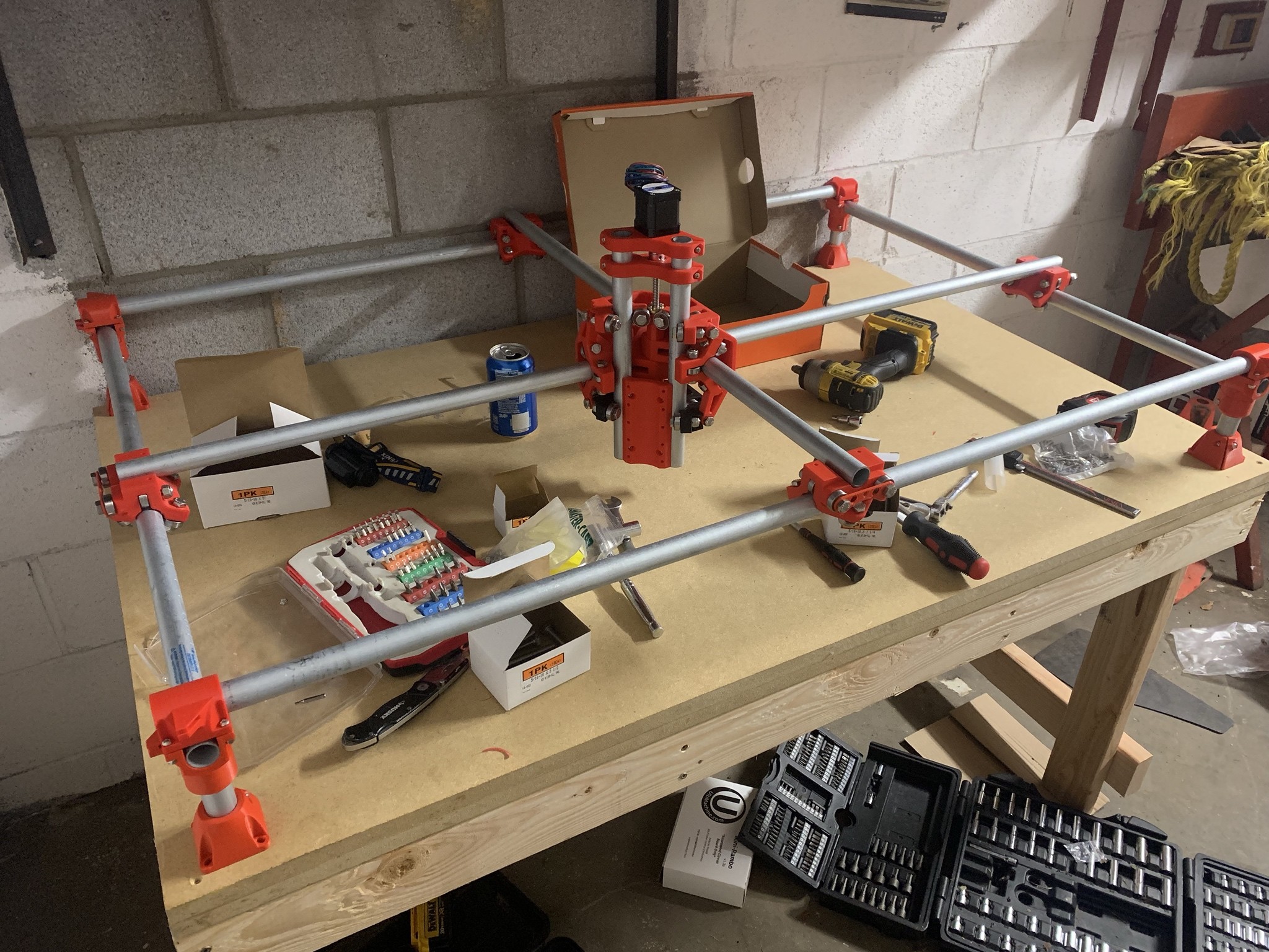
Of course, my printers have been running ever since. The parts are a joy to print–tolerances are great, you can really tell they were designed for 3d printing, etc. I ordered the hardware from McMaster (only because I’m not sure what I want to do with the electronics yet, and I’m anxious to start building) and once it arrives I’ll start assembly. Oh, and funnily enough, my girlfriend’s father started to build his own router a few years ago, but once he got to the electronics he gave up–so I got all of his hardware for free. Some 80 bearings, a bunch of belt, pulleys, lead screws, etc. Haven’t measured anything but the bearings yet–and they are 608 2-RSs. If nothing else that will allow me to get the mechanical side done ASAP.

My impetus for getting these machines is that I’m going back to school this fall and I’d like to be able to make a few bucks here and there to help with that (and if you didn’t guess from this post, I’m kind of a machining/creator junkie). Of course I have some particulars in mind (having my own machines has been running through my head for years along with millions of project ideas) but if you want to see that, you’ll have to follow along :slight_smile: Sizing of the machine is based off of what I want to do with it. If I need more (or less!) I can always change out some conduit and belt easily enough.

Pictures coming soon! Not a lot to see yet. Hoping to build my table Sunday.

Well you have my attention. Can’t wait to see what you think. since you have an xxl I recommend building this one smaller for some metals perhaps?

Kinda crazy with school, you get out what you put in, sounds like you had a cruddy group. Once I found a good group we just had such a great time and wonderfully divided workload.

Ugh. I was typing a reply to this earlier and my power went out (never happens) 9.5 hours into the XY piece print. Fail.

Anyway. I have considered this and I think it’s something I’ll explore depending on how this build goes. I did design a VMC style machine earlier this year that is entirely built out of 2D plates. I designed it this way because I still have access to a big daddy Trumpf fiber laser through my old job… but never got around to sending over material/DXFs. The design was a mix of those plates and epoxy granite to add strength and of course to help with vibration damping (for those who don’t know, epoxy granite is roughly 10x better at vibration damping than cast iron, which is used on pretty much every machine tool out there). I basically designed the plates as molds that stay in place after casting the epoxy granite. I specced it out with linear ways, ClearPath servos, and had a counterweight system designed for the Z axis. I’m no machine designer but I think it would be a decent little machine.

What I’m getting at is it might be interesting (albeit a lot less easy) to cut those pieces on a MPCNC. So yes, this is something I’m going to consider doing. But for now, cutting metal is not as high of a priority. Since these machines are so cheap I would have no problem building a second smaller one to play with machining non-ferrous metals.

Just found out I have to print 120 pieces of something for work, so all 3 of my printers will be busy with that for a couple days. Which means I will indeed probably build my table tomorrow. Will be sure to post pictures of that.

I wrote a long post here a couple days ago but I edited it immediately and I guess I deleted it or it got caught in the spam filter. The basic gist was that I didn’t get much done because all 3 of my printers were taken to the office to run 24/7 (along with myself, lol) to make an upcoming order… Been working really hard to catch up with other jobs since that order shipped and preparing for this bad boy to get installed in my office…


Now that it’s installed, and I brought one of my printers home, and I’m not working 7 days a week anymore… progress on the MPCNC can continue. :slight_smile: In the meantime I have ordered everything (thank you for the quick shipping, Ryan!)

Making progress. Slow progress, but progress! I’m sick, too, so double whammy. :slight_smile:

Realizing the only thing holding me back is the table so I got home from work today and glued up my top. I don’t have a good flat reference surface to work from, so I figured my best bet to get a flat top was MDF. Pretty simple, just 2 layers of 3/4" MDF with glue between the two. Screws from the underside to provide clamping pressure for the glue. Sitting on my saw horses curing it’s as flat as any straight edge I have. As flat as the conduit is straight at least. So I think that is accomplished… I just have to move it into my workshop after the glue cures and build some legs/undercarriage for it now. Side note, 55"x40" is a lot bigger than it sounds on paper. :slight_smile:


I also started to assemble some of the 3d printed parts. And I gotta say–Wow! They fit together like a dream. My printers were well dialed in before I started but I didn’t expect everything to fit so well without any tinkering, sanding, drilling, etc. Well engineered :slight_smile: I’m very impressed and happy with how that’s coming. I’m still waiting on maybe 10 more hours of prints to finish. I can’t wait to start assembling the center section/Z axis.

1 Like

Seems like all my posts are disappearing as soon as I make them… so we shall see if this one makes it through the spam filter.


Felt like I got a lot more done till I looked at this picture. lol! I’m still sick though so taking the scenic route…

X/Y seem to be very perpendicular but not sure on the Z yet. My holes for those C tension screws were a bit undersized so it seems like even with the nut loose it’s still exerting more pressure on the assembly than it should be. Also, anyone know if the z axis leadscrew nut is supposed to be on top or bottom? Instruction pics I saw showed it on top but also say the screws do nothing but keep it from rotating. If it’s on top the screws would also be holding the Z up or no?

Still on track to be moving this weekend… as long as I can find my soldering iron :stuck_out_tongue:

But for now I’m going to bed since it’s 3am…

2 Likes

Leadscrew but on top. Screws just keep it from turning, and should be slightly loose.

1 Like

Apparently I’m inventing new problems. I don’t have any zip ties that fit in the corner pieces. They are all just slightly too big. So I guess I’m going to walmart… at midnight :slight_smile:

Other than that, I got all the wiring extended and hooked up. Powered on the mini rambo and all steppers move as they should… Z axis moves perfectly. Happy!

Walmart trip at midnight. Time to break out the good pajamas!

3 Likes

It looks kinda awful but I think it’s possibly due to the sharpie I used… maybe? hopefully. The fact that the starts and ends match up as they should gives me some hope. Still some fine tuning to do obviously…

Edit: again with a pen…


Hmmm. Dunno what to think. Using the pen holder and pen is zip tied tight. no movement between pen and holder. flex between pen and tool mount, obviously. I did notice one of the bearings isn’t touching the y rail so there is slight movement in the middle assembly if i push on it with some force, but not enough where the pressure from the pen is causing it to move. I’m kind of stumped, it looks like the actual movement from the machine is not smooth. Could it be a belt tension issue?

Could just need to wear in the bearings on the conduit. You may want to also look at the tension bolts in the middle assembly and make sure that they aren’t too tight. Also check the X and Y rollers to make sure the compression bolts (the 2.5″ bolts that run through the Roller Plate) aren’t too tight.

1 Like

Thanks BT. The tension bolts in the middle assembly are completely backed off with only the nylock engaged. Though the wear pattern on the conduit is much bigger on the middle X/Y rails than the outer X/Y rails… Which may make sense since the two outside rails on either side only hold 1/2 the weight…

The other tension bolts are only engaged enough to get all bearings in contact with the conduit… though I did try with them looser and it made no noticable difference.

Did my first cut tonight!

Realized that the endmills I ordered were 2 flute, not 1 (they were the top rated item on Amazon when I searched for “single flute 1/8”, shouldn’t shop while tired I guess) but they ended up cutting decently in this red oak scrap I had laying around. Did make a chip, albeit very small, at 17mm/s. DOC 1.5mm and optimal load of 1/6 tool diameter. Helical ramp of 2 degrees at 6mm/s. I obviously have a lot of room to go deeper and faster (lol). I was quite happy with the surface finish, feels smooth to the touch. Almost forgot, this was climb milled…

Before I cut any more I need to sheathe all my wiring and put some holes in the table. Have not fully decided if I want to raise the feet up 3/4" so I can have my 4" of Z travel or just put my spoil board on top of the table and lose 3/4".

Thanks to everyone who helped. It turns out most of my issues were caused by having the feed rate override at 300% somehow. And by somehow, I mean I was messing around with repetier host and forgot I touched that slider. :slight_smile:

Shhhhh, it was a bug for sure, none of us make mistakes. Well at least you know your machine can move real fast if it has too!


Congrats.

1 Like

Yeah I’d like to point out from my end it looked like the issue was the pen mount not being able to keep up with the machine at that speed. So that’s a good sign!


Cutting good, other than the fact that I can’t get repetier-host to keep the steppers energized when the job finishes, so the Z starts to drop into the work.

I experimented a bit with feeds and speeds and got a lot more aggressive with my cuts. Still feel like I have a lot of room to grow, though. But I wanted to cut something more than a few holes, so I pulled out a file I made that I’ve wanted to cut for a while… I think it turned out pretty good. Obviously I wouldn’t use mdf for the final product but it was scrap I had laying around. It wasn’t too awful with my upcut bit but there were quite a few fuzzies to remove. I’ll definitely be ordering a few downcuts just to experiment with, if nothing else.

There is a setting in repetier to kill steppers after job completion, or something like that.

It does not do anything for me

There are only two way they will shut off, the last few lines of your gcode M84, or the repetier toggle. If it not an issue with repetier then how do you generate your gcode and is there an m84 present?


1 Like

Oops. Yeah you’re right, apparently the fusion post does an m84 by default. I’ll have to fix that…