Oops. That’s a bummer.
I’m actually surprised it doesn’t happen more often though. I know I am not detail oriented enough to catch these things.
Oops. That’s a bummer.
I’m actually surprised it doesn’t happen more often though. I know I am not detail oriented enough to catch these things.
Yeah I have enough trouble thinking in 2D 3D with mid point constraints and fixed or parametric my brain would be the melted puddle
Well it is funky and not an easy catch. there are two bolt holes defined. It is anchored on that line (center of the bearing my main parametric sketch), the other is defining it left to right (dependent on the Z axis sketch). Normally it is never that close together (90 degree planes is pretty common). This is just a special case…such a flub.
The second hole is actually defined differently from the first even. So in this sketch I screwed up twice. Same location overall though. The good part is the only other flub is the bearing stand off, should be defined by this hole, and was defined by the same point. I must not have turned off that other sketch in the middle of it all.
Ouch. Well, glad you found it!
I guess the clamps are designed parametric to the core?
Because my analysis of the clamps shows the same result, you should update these as well.
Yes everything is parametric.
Incidentally, cap head screws may have clearance issues on the Z axis. You might need 4 hex bolts for the bolts on the core adjacent to the Z axis, or you might need to grind down the heads on those cap head bolts.
Edit: I said 4 bolts, I meant 8. Or maybe some will squeak by. Test fit and you will find out.
@vicious1
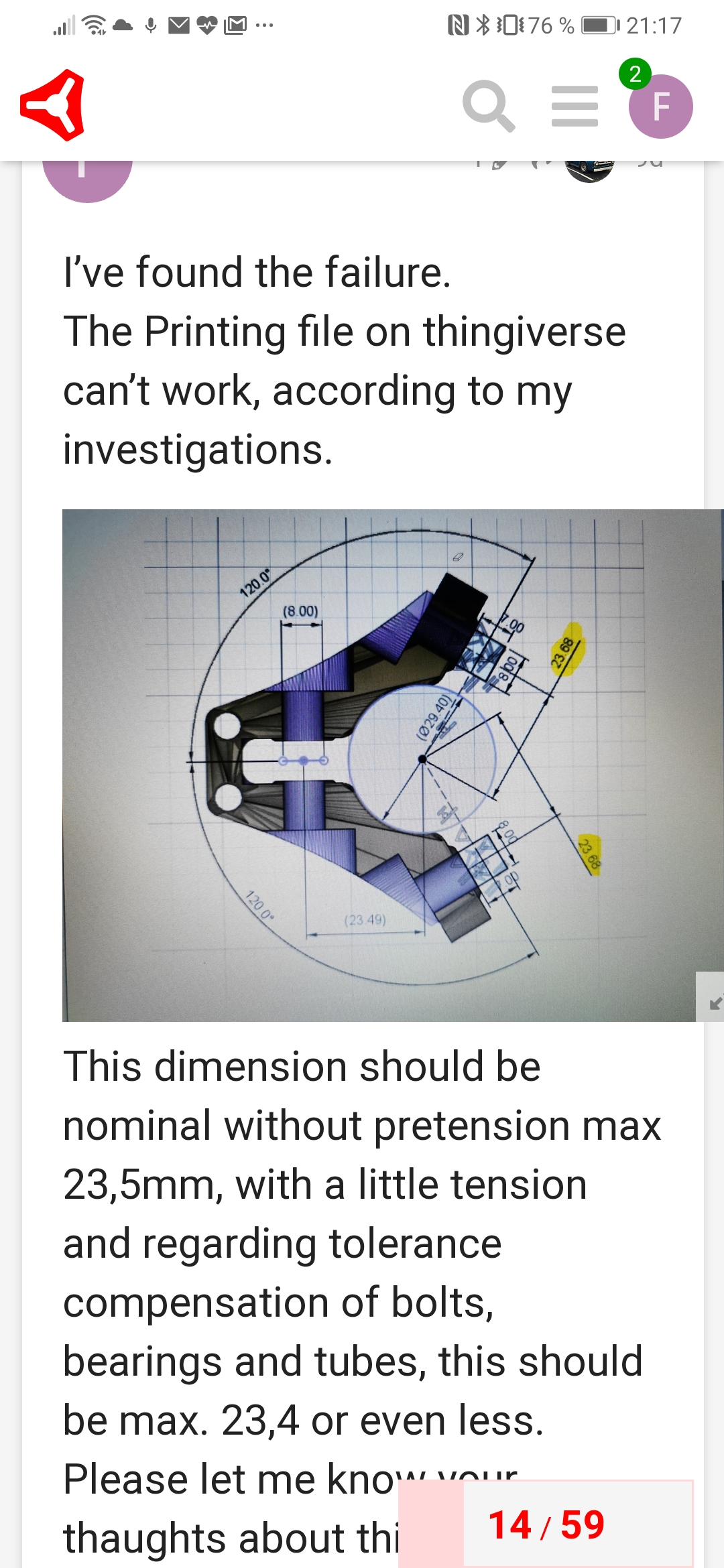
Hi There,
just downloaded the new version, but now i miss the Core_F_Primo in the package ?!

Could you tell us when its completly updatet ?
Thx
edit: The missing file ( core-f-primo-v1.stl)
Can be downloaded on PrusaPrinters
@vicious1 I’m in the last stages of my 25mm build. I was seeing some play as well but was able to eliminate it by tightening the clamps, but I worry that I might have overtightened them.
Should I reprint the core parts? I’d need to get some more PLA first.
Also, what’s the benefit of the new trucks you just released?
Thanks!
All the new core files are up. I just double checked.
If it is snug, leave it alone, if you break a part, reprint them all.
at the print in Cura on layer high line 485 (CORE) hes getting out of control,
hope thats not bad
cause its my last filament
hey, guys,
I have successfully crossed the Alps and am now back here 
Thank you very much that you have taken up this topic so intensively!
The new core and the clamps were printed to me in the meantime. Yesterday I installed and tested the parts directly.
default assembly
I have assembled everything, the rail is still about 1mm away from the stock.
altered assembly
By this method I could bring the situation a lot closer. The rails X- and Y-axis were only slightly wobbling.
After I installed the core, it has probably stretched so far that the core only wobbles a little bit. At the moment I would say it should fit.
Do you have any other experiences with the new version?
It would be interesting to know if the adjustment only works for me, all other rail clamps are working fine and can be adjusted too much like for the trucks.
I will continue to assemble the MPCNC, if I can still help just let me know.
Cheers Chris
Hey how,
Sorry, I have bad news…
I have connected the steppers to test the movement.
The core is wobbling again. I have retightened the tension bolts again, it can’t get any tighter. It didn’t do much good either, one layer is not in contact (~0,5mm distance).
It is impossible to move the core, but with small steps the core wobbles and it rattles very hard.
Must be something with the pipes, hardware or printer. Mine is super rigid.
Please run both tests.
Good evening,
i have spoken with my friend. Sorry, I had in my mind that the calibration test (XY axis distance and square) was correct.
He has printed it again today and the following deviations have occurred.
X +0.9mm
Y +1.3mm
The steps/mm were adjusted and we got the following measurements:
X 150.1mm
Y 150.1mm
diagonal of the small square 149.8mm
The measurements showed a deviation of less than 0.6mm. We are currently reprinting the clamps.
Tomorrow I will install the clamps.
I will get you up to date.
Good night
Chris
If you are not printing the new Core, you need the modified clamps that I did not make. My clamps will not fix the issue without also replacing the core.
If the printer was that far off you should also check the z axis and extruder. 150 should be correct so I suspect something else is wrong like loose belts. Steps per mm are exact numbers (except the extruder).
Hey how,
we printed the clamps again after the print test had been adjusted
Now the bearings are also in contact with the rail. We left the core in the V1 for the time being - the deviations are probably not that dramatic.
I have already printed a few test drawings. They look good so far.
When changing the direction the Y-axis swings back, but I would say it is because of the length (1200mm).
Cheers Chris