We finished printing all the pieces this week. Of course I started to assemble the Primo right away.
The trucks and the z-axis fit perfectly. But I also have the problem with the connections between core and the x- and y-axis. The core wobbles a lot and tightening the tension bolts did not bring any improvement.
I followed your altered assembly steps but unfortunately it still wobbles.
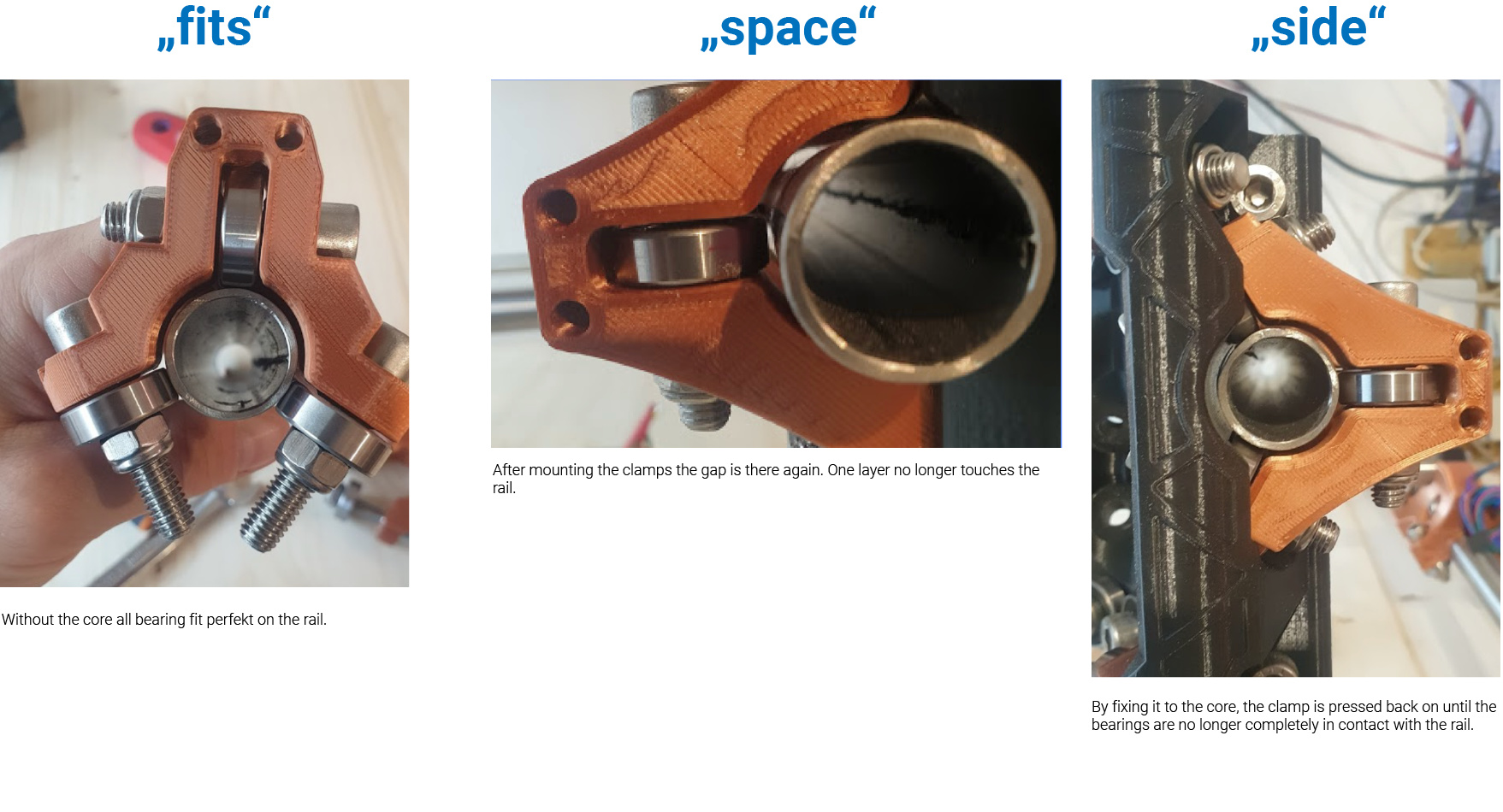
I removed the clamps and adjusted them to the rail. It fit perfectly.
please see next Post -> Picture “fits”
After mounting, again one bearing is not in contact with the rail.
please see next Post -> Picture “space”
I don’t know how to fix it without adjusting the parts.
I checked all the holes and the screws fit in without any problems.
But I also have a problem understanding. please see next Post -> Picture "side"
The clamp is attached to the core in two places. When the tension bolt is tightened, the bearings on the core should tilt a little inwards and the outer edges closer to the rail. This way the position of the tension bolt moves outwards and the distance becomes bigger again.
@anon74685196 vll you can help me to understand the function.
Gladly I support you in troubleshooting and in finding solutions. The next two weeks I will not be at home but as soon as I am back I will support you.
I’m happy to support you!
Greeting Chris
p.s. Respect to all who contribute their part to this project! It is really brilliant! Thanks!
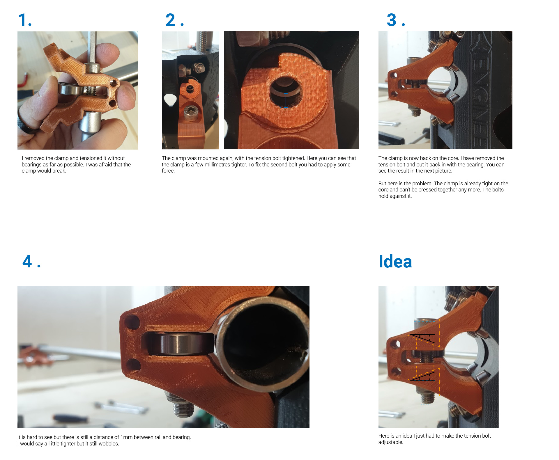
Please try tightening the core clamp tension bolt first, no bearing. The add both the core bolts and bearings to it with no nuts. This will allow you to get it fully seated and tight. Now add both nuts equally to tighten it into place.
Now you should be able to remove the tension bolt and add a bearing. Is it tighter?
I am printing another size machine with the exact same offsets. I should be able to test it tonight or tomorrow. I am not getting any issues with the other size.
Have you printed a printer test, Printer tests and calibration? Quick print and tells us a lot about your printer calibration.
Looks exactly like my problem, I also tried a lot, but in the end I printed new Clamps with closer horizontal bearing: https://www.thingiverse.com/thing:4564508
But before printing these you should first check the diameter and roundness of your tubes, maybe rotating of the tubes helps.
Sanding of standoffs and overtightening is an option, but I can’t recommend it. If you prefer sanding the standoffs instead of printing new clamps, only sand the clamps. They are easier to reprint.
There does seem to be a difference in my J parts to my C parts, but I had a print issue and had to restart them, so hopefully I can test first thing tomorrow.
Well bummer, sure enough it does not fit. I then triple checked my 25.4mm parts, fit perfectly.
Hmmm, I will have to go over the model with a fine toothed comb. I have no idea what could be different. I do know how to fix it but I am going to spend a little time looking for a fixed number that should be a variable. I don’t like thinking some models need an offset and others don’t and none of the other parts have an offset and fit perfectly. There must be a missing variable. Odd that the parts are a different size, you would think if I was missing a variable something would be the same but it is not.
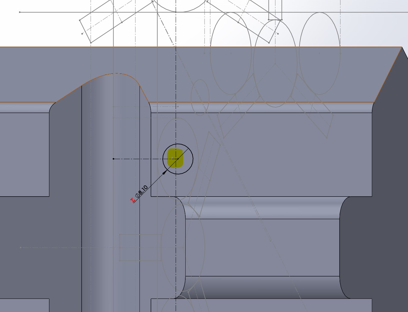
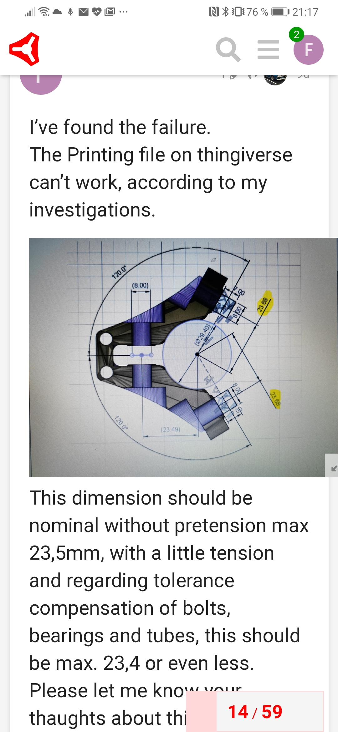
The bolt holes are supposed to be on that dotted line, instead they are locked onto a sketch behind it. That makes them 0.2mm off on each side, and those holes spread the part at an angle so that is compounded. So the 3rd bearing is right, and we checked all those dimensions many times. Turns out the core holes are just too wide.
Well it is funky and not an easy catch. there are two bolt holes defined. It is anchored on that line (center of the bearing my main parametric sketch), the other is defining it left to right (dependent on the Z axis sketch). Normally it is never that close together (90 degree planes is pretty common). This is just a special case…such a flub.
The second hole is actually defined differently from the first even. So in this sketch I screwed up twice. Same location overall though. The good part is the only other flub is the bearing stand off, should be defined by this hole, and was defined by the same point. I must not have turned off that other sketch in the middle of it all.
Incidentally, cap head screws may have clearance issues on the Z axis. You might need 4 hex bolts for the bolts on the core adjacent to the Z axis, or you might need to grind down the heads on those cap head bolts.
Edit: I said 4 bolts, I meant 8. Or maybe some will squeak by. Test fit and you will find out.
@vicious1
Hi There,
just downloaded the new version, but now i miss the Core_F_Primo in the package ?!
Could you tell us when its completly updatet ?
Thx
edit: The missing file ( core-f-primo-v1.stl)
Can be downloaded on PrusaPrinters