So about a month ago I decided I needed a full sheet 4’x8’ CNC router in the shop to build some of the kayaks and canoes I want to start working on. Not to mention the million other uses I could find for such a capable tool. I started to look and man $5k for a plug and play option was kind of out my price range. So the search for more economical options began. Leading me here and thus building my own LR2.
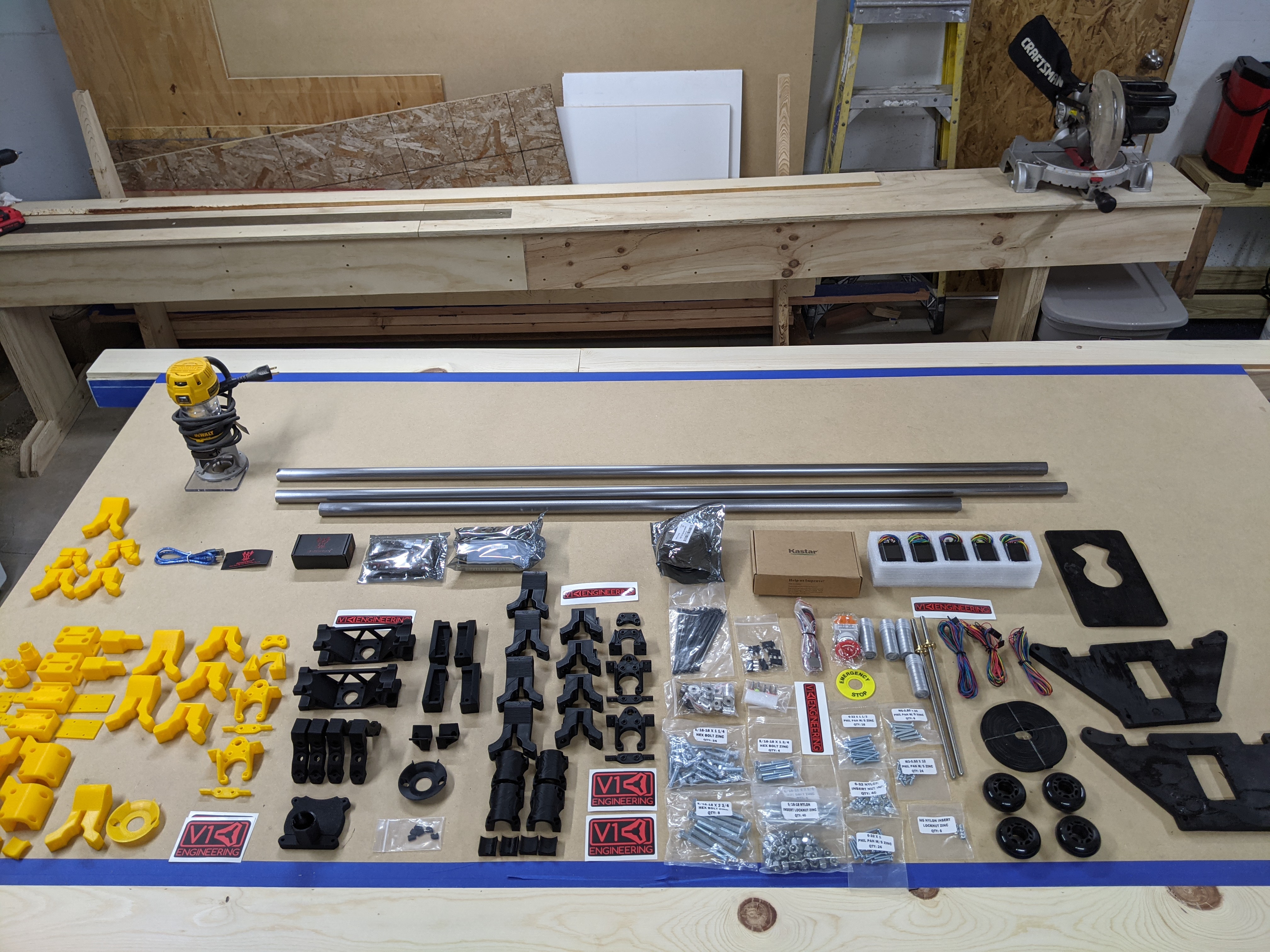
So i printed all the parts out in yellow to match the Dewalt Router. I used PLA on my Monoprice Select Plus set at .2mm layer height 60%infill with triangles and .8mm shell thickness. Took about 40hrs to print all the parts and I used an entire 2.2lb spool of filament. I upgraded the belt tensioning using Karlis Zalitis’ design. I also used his Z end stop design as well works great. Check him out on Thingy.
I designed the brackets to hold the SKR and screen to slip over the Yplate. It requires a couple small notches to be cut out of the top of the Y plate but no biggie. I secured the SKR to the board with hot glue. ( Side note - Hot Glue releases with ISO alcohol) That way if I need to replace or troubleshoot I can simple spray some ISO on the glue and pop it right off.
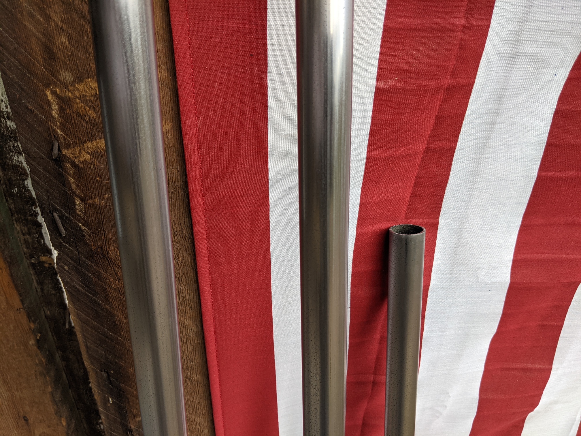
I went to get the SS Tubing from Metal Supermarket but they were out of stock so I just got the standard steel. It was black and dirty but after ten minutes with an orbital and some 220 grit they were smooth and shiny.
I soldered all the connections and added JST HX connectors to all the connections on the board. I used the pre crimped 18awg silicone wire JST HX kit for that, makes life so much easier. I also cut all the wires right at the stepper and soldered on 18awg shielded 4 strand wire to each motor. I used 24awg 4 wire for the end stops and put two together where I could. I added JST HX connectors to the board side of the end stop wires and 2.8 type crimp connector at the switch so I could swap them around to troubleshoot if needed (glad I did this)!
I used the SKR 1.4 Turbo and TMC 2209 drivers with a BTT 3.5 V3 TFT screen. I cut the power supply barrel end off and soldered on two wires to get screwed down on the board. This way you can avoid any issues with those little green and black connectors that come with the control boards.
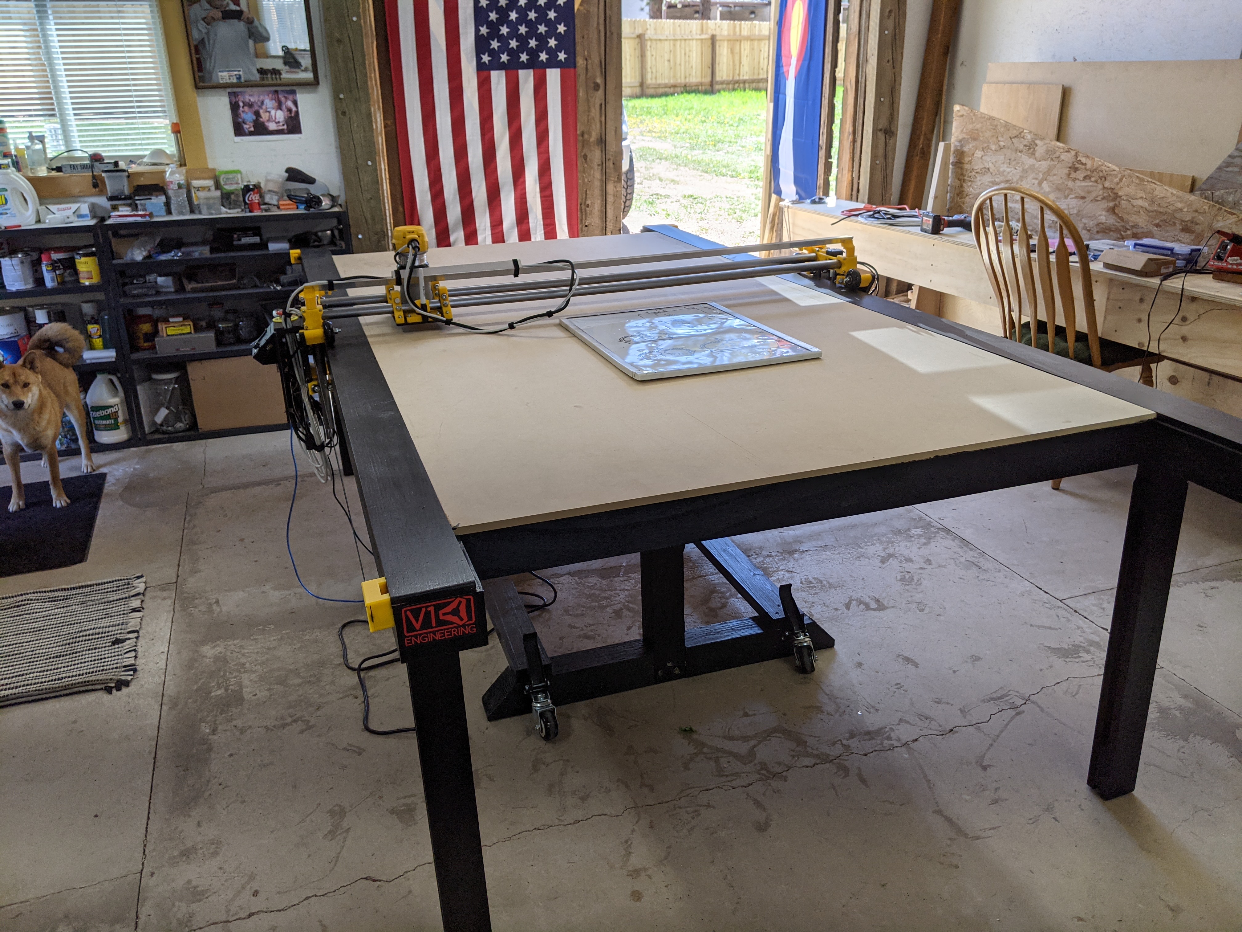
The table was constructed from one sheet of 3/4" plywood, one sheet of 1/2" MDF and three 4x4 posts. It uses some 1/2" pipe for hinges and rotates on the y axis almost 90 degrees vertical with the LR2 mounted. The legs store in the table and it only takes a few minutes to set up. I added some work bench type caster so I could roll to the work area and set down stable and flat. I added some leveling feet to the legs to adjust for uneven surfaces. I have a 3D cad model of the table if anyone is interested. here’s the link top the video of me setting up the table without the lowrider on it.
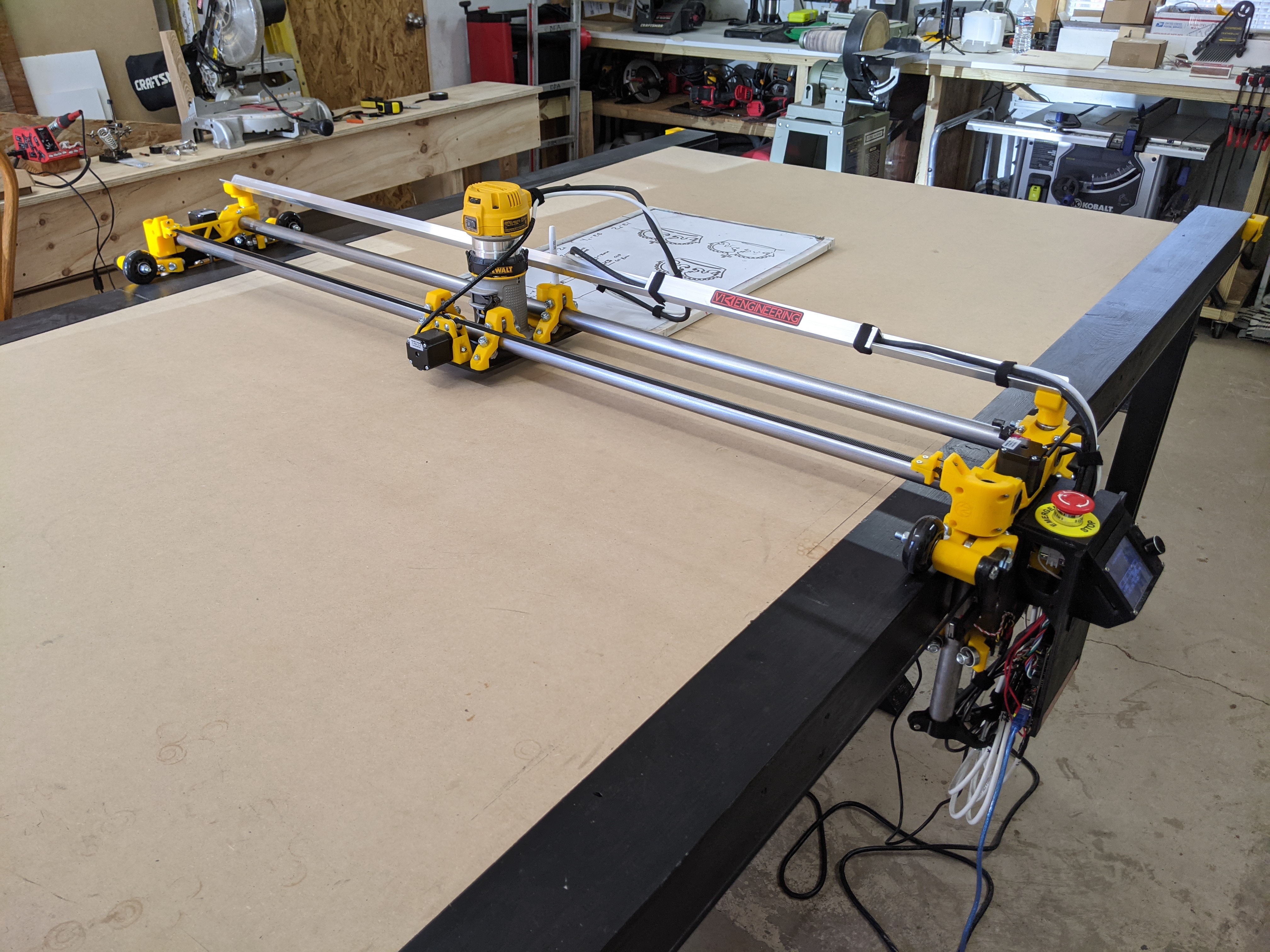
Heres some more pics as it sits. I plan to add a drag chain to the gantry for wires and connect to my soon to be built on my LR2 dust collection system.
I’m planning to mill out the aluminum ZX gantry connectors and add a lexan 611 plate with LED’s and a dust skirt as well. I want to add a laser and be able to cut vinyl as well so this should be a fun project moving forward.
Thanks agin to evryone here and especially V1 Engineering for providing the average maker an economical way to get a CNC router setup in their shop/garage.
Damnit I knew I would screw something up LMFAO I peeled it off today when I finaly got the TFT working! Thanks for the props, I bought the V1 printed parts as a backup but now I think I may have to build one for a plasma cutter as well!
LOL that’s alright, we will live. Definitely give the Plasma a try, I am finishing up an MPCNC milling machine and now am interested in Plasma myself. I like to hear other people’s plasma experiences because it seems finicky. But enjoy your current machine for a bit first!
Vinyl is toxic when burnt. You may also want to try the drag knife cutter. There is one in the shop and that is what something like a cricut would use.
You may want to wax the tubes. Just johnson paste wax or something. I live in Colorado (and I saw your flag) and I actually haven’t had problems with rust or anything. But I also left mine dark from metal supermarkets.
Where’s the crown?
Really great build. The table is awesome. Thanks for sharing.
Sorry if I made it seem like I was planning on cutting vinyl with the laser LMFAO! I wouldnt do that! I was planning on adding the drag knife as well as the laser.
Looking at the NEJE A40640 its only $259 right now, from China.
So the NEJE A40640 is on the way. More to come once it arrives and we start designing a mount and getting it to function with the V1 firmware. Any suggestions?
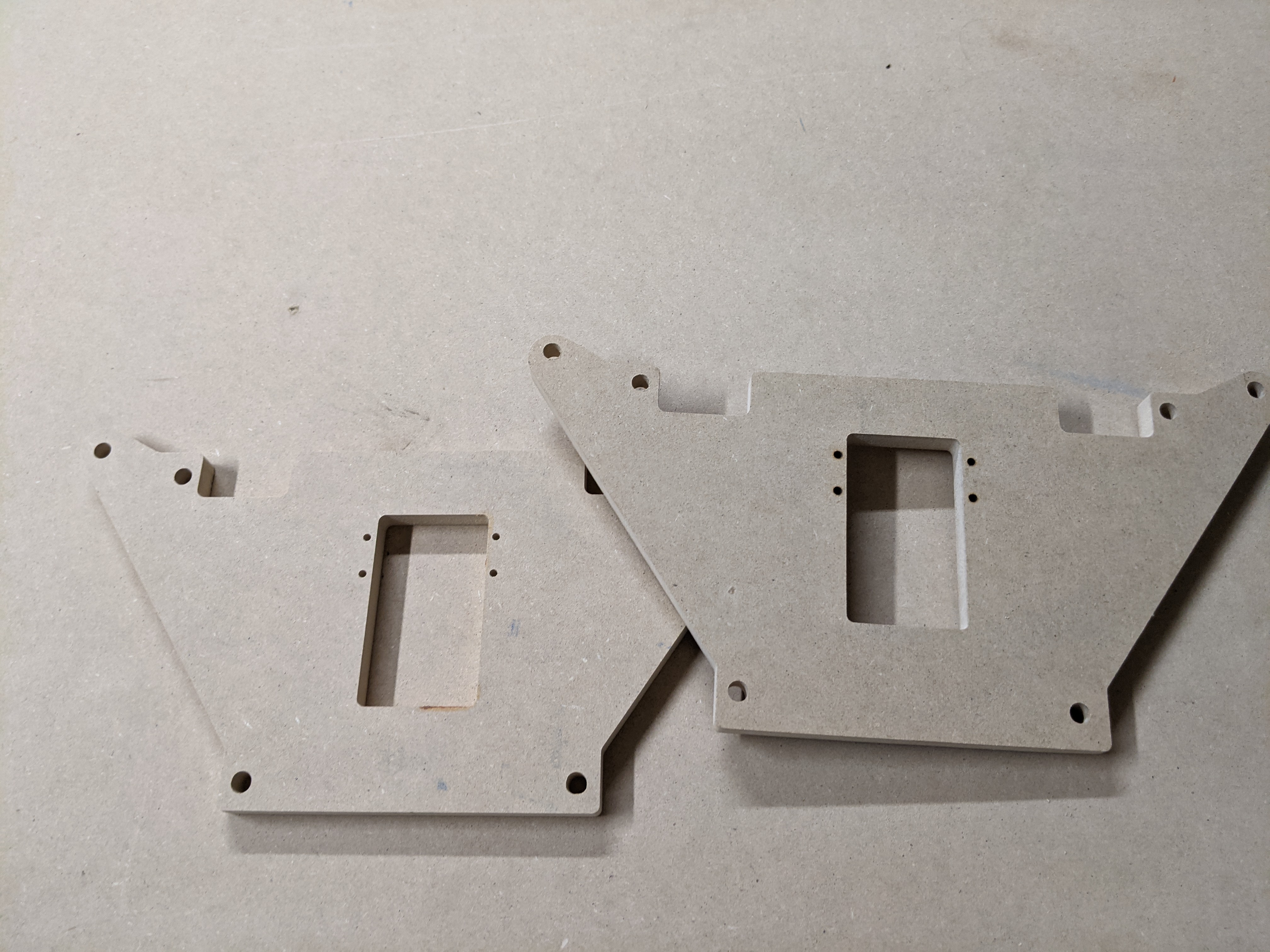
So after printing out the crown on dry erase board. I stepped it up to some HD Foam and ran some tests. All good. Learned allot with Estlecam. Loaded up some 1/2" MDF and cut out some Y Plates. I noticed the ones I created out of 3/4" plywood started to warp. When I got the kit I realized the bundle
hardware was for 1/2" wide Y plates so I ran the ones I made through the planner. Well that caused them to warp in this dry Colorado air so I needed some new ones. My wheels wont track straight on that side causing the Z tubes to run into the table causing skips and errors in milling. These should help! Check it out!
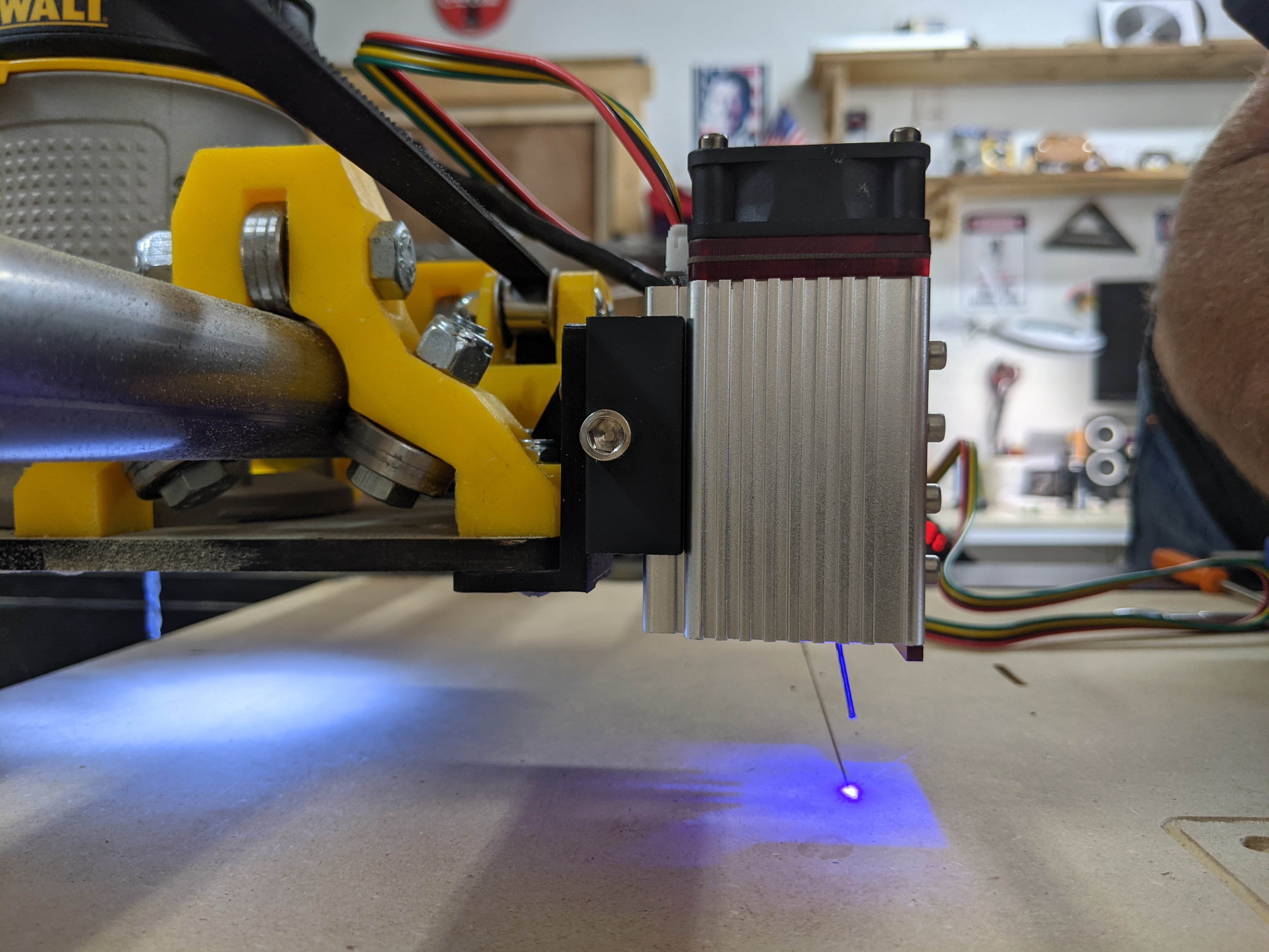
Laser is here and mounted up. About to run my wiring. Just want to verify I plug the connections in to right spot on the SKR 1.4T. The 12v and GND go to the FAN 0 connector. The PWM signal I would like to assign to pin 2.0 on the servo connection. Is that possible or am I going about this all wrong?
If you have issues keeping them straight and true, you can fit some angle aluminum across the top and tie onto the wheel bolts. It really helped keep mine straight in our humid weather
Alright got it all hooked up and it works like a charm. The Fan 0 connection controls power and PWM so no need for the PWM. I would like to see the laser temp so is it possible to run the temp wire to one of the thermistors connections and monitor it there?
I have the exactly same laser that runs flawless with a rambo V1.4 board but does not wanna work with a SKR 1.4 , 1.4 Turbo or SKR pro 1.2
What did you change in the Firmware? and what laser control board did you use? (mine came with 2 different boards one with a lcd and a very simple one with 3 ways to connect 12V, GND and TTL )
Don’t change anything in the firmware. Simply plug the 12v and GRND connections into the FAN 0 connection on the board and your good to go. I didnt use either control board that came with laser. I just ran a wire to laser from SKR. NEJE 40w will take 3.3v-12v to fire and control PWM.
Thank you.
I was reading the board and @Tuco made a nice write up about using pin PC9…and didn’t work at all for that laser on the SKR Pro.
I endup installing a spare Rambo on my LowRider to use the laser.
next week I will be able to remount the SKR and try the laser the way you did.
Thank you again.
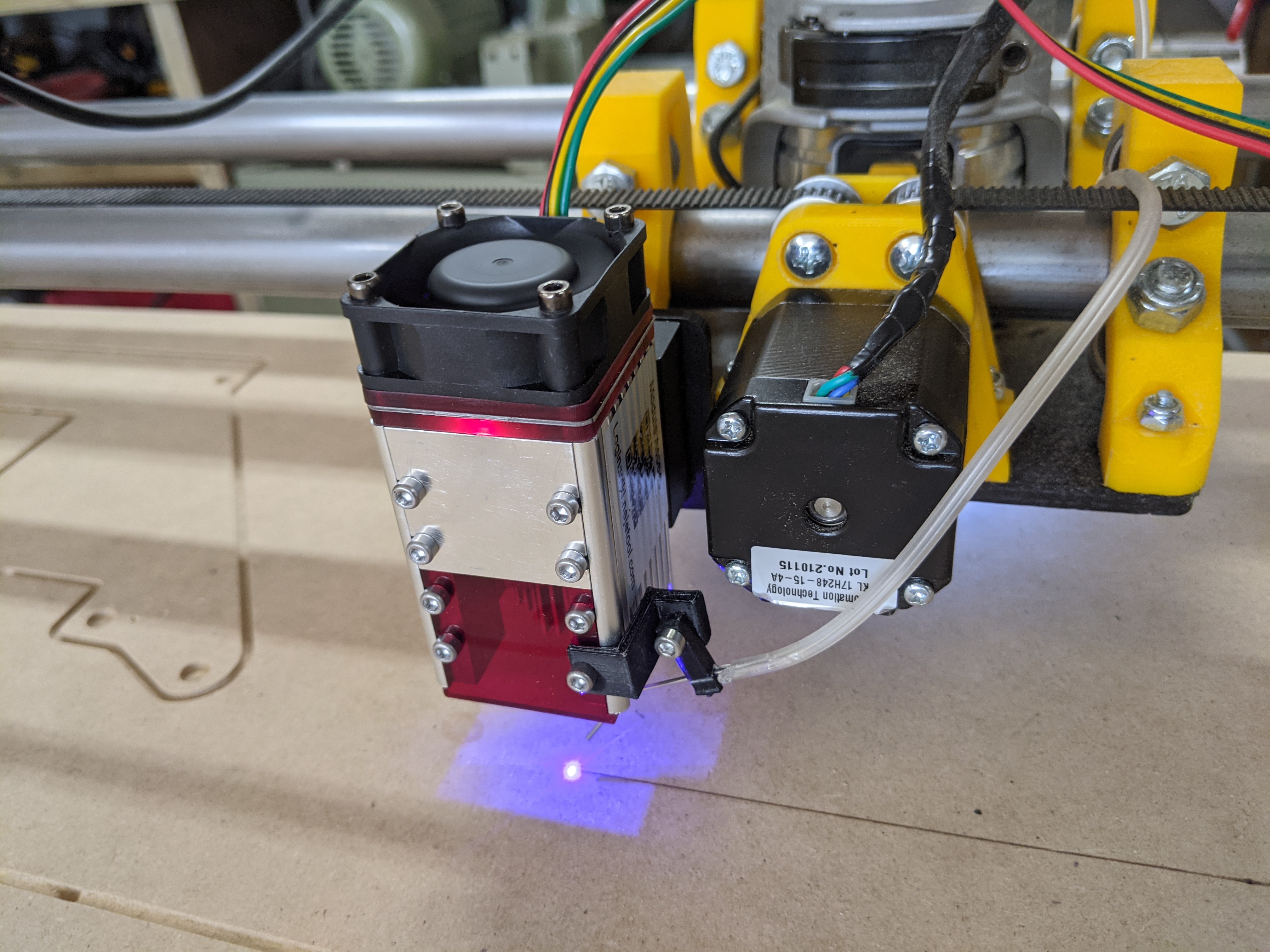
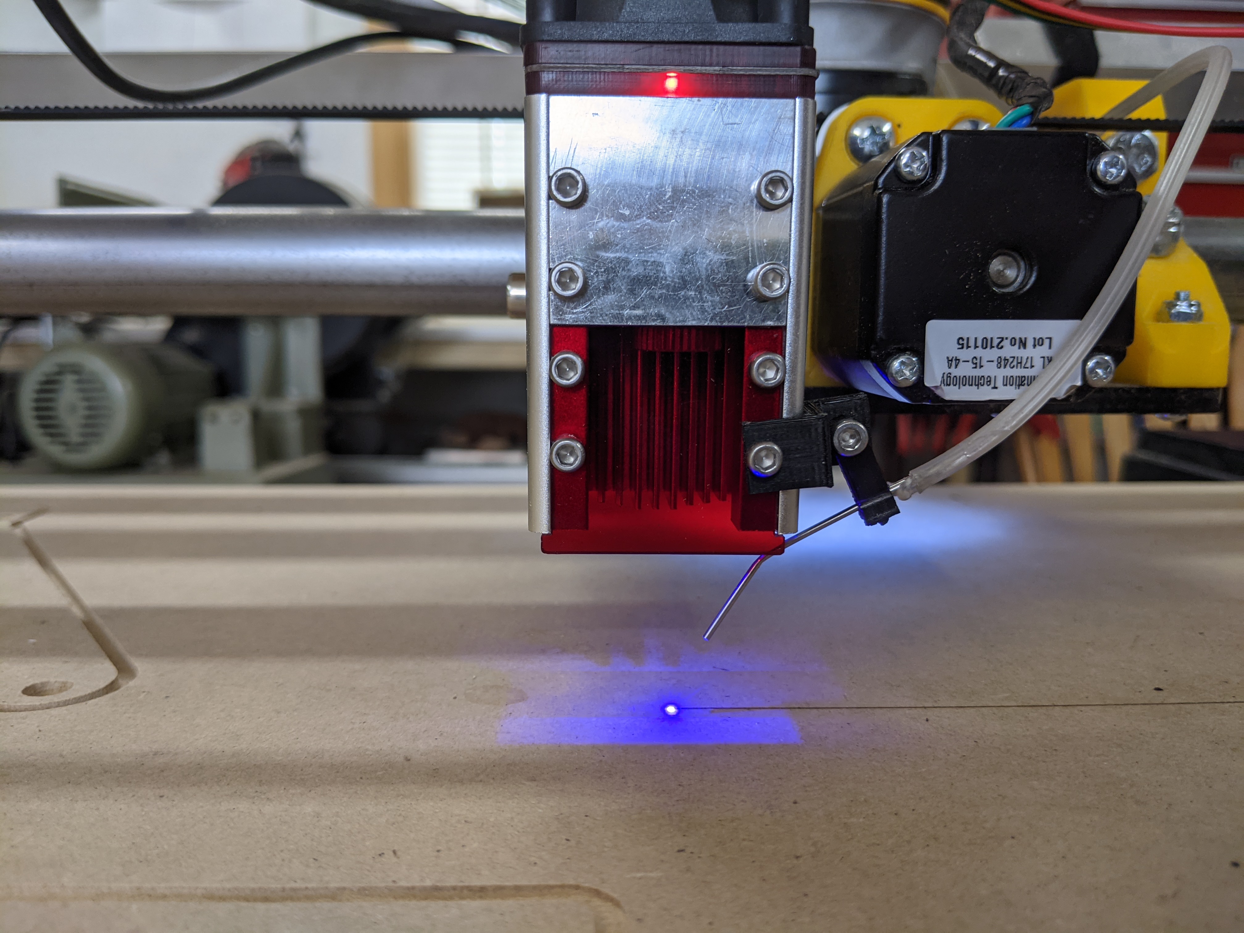
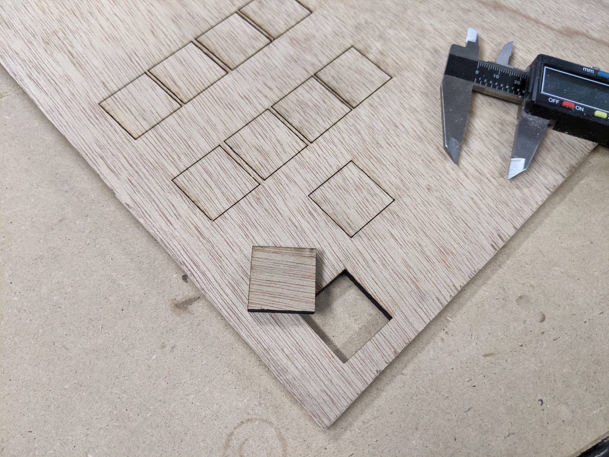
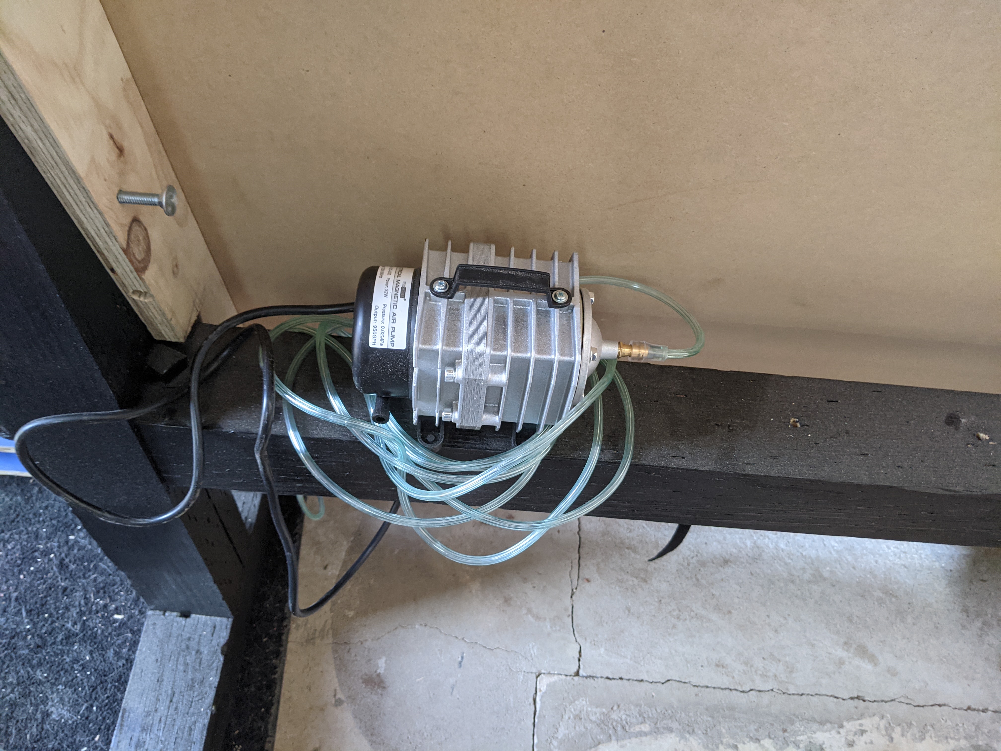
Since the lens is set on the 40w model I use the touch plate from V1 to move the laser into position on the Z axis. I figured out my focal length for engraving is 17.33mm and for cutting I adjust it to 18.83. this drops the focal point to 1.5mm below the surface. Air assist is clearly key. One of my tests last night was with and without air assist and the results are clear. With air assist I was able to cut through oak veneer 1/4" plywood @ 10mm/s 100% power 5 passes. Without air assist it took 10 passes and still wasn’t completely through. Not to mention the charring and burn marks on top and bottom. I am going to order a large sheet of stainless mesh for the table. I used a scrap piece of mesh I had for testing.
Thanks alot! I’ve already been thinking about how to figure out the air. I see people build custom air-nozzle cones that goes around the laser - but I think your approach is good enough. I have an air compressor in the neighboor room, and thinking of running some pipes to have air acces close to the MPCNC. Some kind of mesh sounds also wise. Looking forward to figuring things out!