I am starting to look into drilling holes in my waste board to attach clamps. I am experimenting with Inkscape and Estlcam to try to figure out optimal settings for drilling all of the 9mm holes with 2mm counterbore around them for threaded inserts.
I drew up two circles in Inkscape, each with line width 0.1mm. The outer circle has 11mm diameter and the inner is 9mm. My bit is 1/8" in diameter.
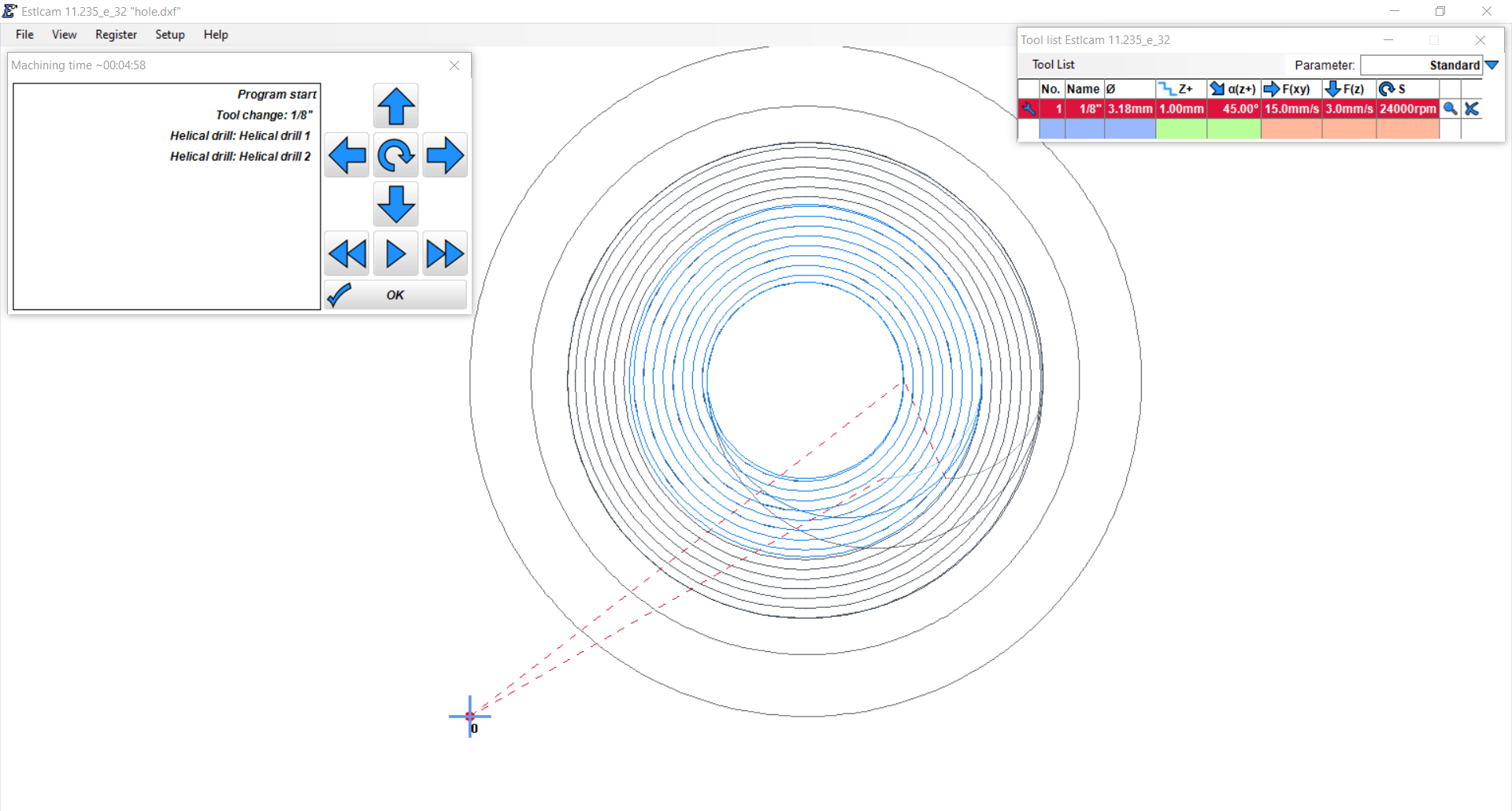
I import into Estlcam and set up two helical drills (outer 2mm deep and inner 12mm deep). The preview shows that it will take around 5 minutes to drill one hole. I am really new to this field, but it seems like an awfully long time… is this reasonable? If not, can you help me tweak my settings to speed this up?
Why not draw it up as two pockets and see how the time differs?
I’ve done very little drilling with Estlcam but have yet to find an explanation for why when drilling a small hole in each corner of a rectangle, the transit speed between holes slows waaaaaaay doen.
Just threw one together with a quarter inch hole, 1/8th endmill, 12 seconds. Feeds and speeds, 2mm Z step, 20mm/s X/Y feed, 8mm/s Z feed, 85% stepover.
Thanks guys for your tips! I am starting to figure out how this works! I switched to pockets instead of helical drilling and I also used the suggested settings and it goes much faster.
I’ve started trying multiple holes now. Is there any secret to easily select all of the holes of each type and apply the same settings to them? Right now I am choosing them one at a time and entering the hole type and depth. I think I might make errors doing it this way.
When I did mine, I put the zero in the center of the hole, and just used that one gcode for all my holes. Drill the hole, move over to the next spot, rezero, hit go, etc.
You can also use the pattern functions in estlcam. Even without the CAD. Just make the toolpaths you want, and duplicate them in a pattern. If you have the CAD and want to just use that, you can edit parameters on multiple paths by selecting them all before changing the parameters. I find this method a bit error prone for more than about 3 toolpaths. Also, editing the tool will affect all the paths that use that tool.
I think helical drilling is still an option and may be preferred.
Well I drew up my CAD in Inkscape and ended up selecting each of the holes individually. The outer holes are just plain holes – at 5mm depth I don’t think helical is necessary and I don’t think there’s a need for a pocket, since the center will be drilled out anyway for the inner hole.
The inner holes are all helical drill to 15mm. It actually wasn’t too bad selecting them one-at-a-time (even though I am using a laptop touchpad!). Estlcam says it should take around 30 minutes to do the whole thing. I am running a test pass high above the surface while typing this to double check that it doesn’t do anything unexpected.
Is your plan to install the threaded inserts and then flip the board over? If so, then you may consider drilling the holes, flipping the board, then surfacing it on the other side.
If you’ll be installing the threaded inserts from the top side, then surface first.
Hmm, good question. It would be nice to put the threaded inserts in from the bottom and then flip the board over, but… I can’t seem to figure out how to do that without mirroring the pattern in either the X or Y direction. i.e. I would end up with the inserts outside of the cutting area when I flip it back over, wouldn’t I? This is because the CNC isn’t symmetric in the X and Y directions.
There are also automatic functions for creating paths. I use exactly this function for doing the dozens to hundreds of holes on my spoilboard. It works great ans you can select the parameters for which features get selected for inclusion.