I’m sorry if this has been asked and solved before but i did some research and couldn’t find something relevant.
To make a long story short, I have passed the crown test successfully and now I’m trying to measure simple squares to assure that my CNC moves as should. Unfortunately a simple 5x5 square end up being measured 6.2 x 6.2 on the actual print.
Ok after your hint I changed my search wording and found this in the forum: Used wrong pulleys (20T) - where and what do I set in Marlin?
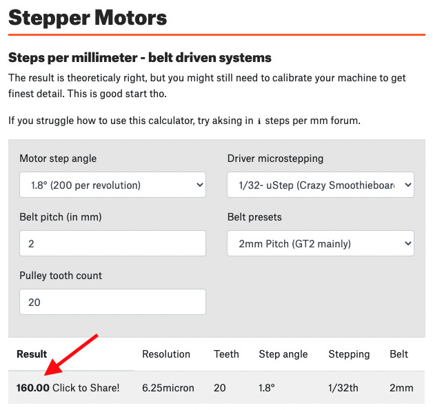
so with Creality 40-42 stepper motors that have Step Angle:1.8 and DRV8825 Stepper Motor Drivers set to 1/32-step using the jumpers as per build instructions, I used the calculator and ended up to this number…
Now regarding Z… I’m using same motor and driver as for XY and I have a T8 lead screw with the following characteristics: Diameter:8mm Lead:8mm Thread Pitch:2mm Number of Starts:4 (any idea what this number is?)
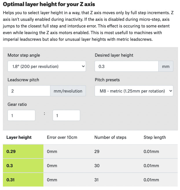
In the config file i left the value for Z to 800 but in the calculator i cannot find such number…
Oops… unfortunately that didn’t work for XY. My config.h file looks like this now #define DEFAULT_AXIS_STEPS_PER_UNIT { 160, 160, 800, 160 }
but i’m still moving 6.2mm where i should be moving 5mm
I triple checked that my Arduino SW is connected as should to the board and i do get the successful confirmation message after upload is completed. I also reboot the board after upload. Still, it seems that changing the values to 160 has no effect to my CNC as it still print over the same 6.2mm square like a carbon.
For what it’s worth, these are the commands from Repetier Host
If your using a 4 start T8 leadscrew with a 1.8degree stepper the standard 800 setting should work. Of course it’s always best to test to be sure.
As a side note that calculator you are using is for determining the best setting for a 3d printer. It is set up to aligning your full step angle with the a specific layer height. This is helps in 3dp where you tend to use the same layer height most of the time. With cnc you don’t use the same layer height ever, because your starting height is based on the material your cutting which will very with each piece, and your depth of cut will vary greatly based on what your cutting into and the shape your cutting out. So the chances of you getting your cut height to be aligned with a full step is small and mostly based on luck.
Thank you for the reply Atom and please excuse my ignorance but what should I do with Z? Based on the first and last lines of your reply and the difference of CNC and 3D printer, i should not bother changing for now; instead actual measure how far Z moves with these settings and take them into account when milling (?). Is this the way to move forward? Again thanks for the time
No excuse needed, sorry I didn’t make it more clear.
What you should do is leave the z steps/mm as is. Then on your machine measure the z distance, command it to move a specific distance in the z direction only. Then measure again and make sure it moved that far. (Just like you checked x and y with the square) just to be sure it is working properly. If it doesn’t move the expected distance come back here and we will help you figure it out.
The whole second paragraph above was me trying to say that the calculator you where using doesn’t apply well to cnc. It’s more for advanced tuning of a 3dp than for steps/mm on a cnc.
The firmware prefers the value saved in eeprom because it doesn’t know you flashed it with something new. So you can rest to firmware defaults (M502) or don’t bother reflashing and just set it in eeprom (M92, then M500).
after forcing it to think it is at 0 it moved 10mm. So G1 Z10 F600 is not forcing it to move 10mm up from where it is, it is forcing it to move 10mm up from point 0 i.e. if i run G1 Z10 F600 twice without G92 Z0 in between, the second time I run G1 Z10 F600 it should have no effect.
At any given time the machine can be set to run in G90 - Absolute positioning or G91 - Relative Positioning mode. The mode determines whether G1 Z10 means “move to 10 up from the Z origin” or “move 10 up from where you are right now.” Apparently (according to this Marlin gcode reference) G90 is the “default” but I don’t know if it resets to that on a reset.
The M503 command should tell you the current mode (and a lot of other stuff)
From what I’ve seen, most gcode creation programs include the G90 or G91 specifier at the top of the code.
It may be that M503 doesn’t show it if it isn’t stored in the eeprom. I don’t know how to find what it is currently set for, but issuing a G90 or G91 will definitely change to that mode.