As the foremost expert (or at least the guy I’ve been reading the most) on lasering glass and tile, what is your favorite laser for making these detailed images? I’ve got a 7watt jtech but I think the dot size is a fair bit bigger partially leading to less detailed images. Proper focus, a level surface and dialing in the software settings would probably help as well.
But buying new toys are fun and your favorite laser is definitely going to solve all of my problems. I see the bangood 2.3 one mentioned a lot; is it that one?
I’ve been able to get decent images on tile and glass with all my lasers… though I do prefer to use some of the first lasers I ever bought – the Banggood and Eleksmaker 2.3W laser modules – most. I, too, think that increased dot size can lead to a loss of detail with the higher powered lasers… and the 2.3W laser, with their smaller die and resultant dot size, seem to do best of the bunch.Thankfully, and in addition, it doesn’t take much power to “engrave” ceramic tiles and glass… so the 2.3W lasers are my preference. Sadly, nowadays, they seem over-priced for what they are… relative to some other modules out there.
That said, in post #88, I mentioned the loss of detail with larger dot size can be mitigated a bit with Lightburn’s “dot size correction”… where dithered images, made up of many extremely short line segments, can “recover” detail by applying a correction to make those overly-long line segments (due to larger dot size) more true to length.
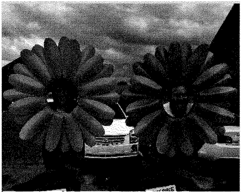
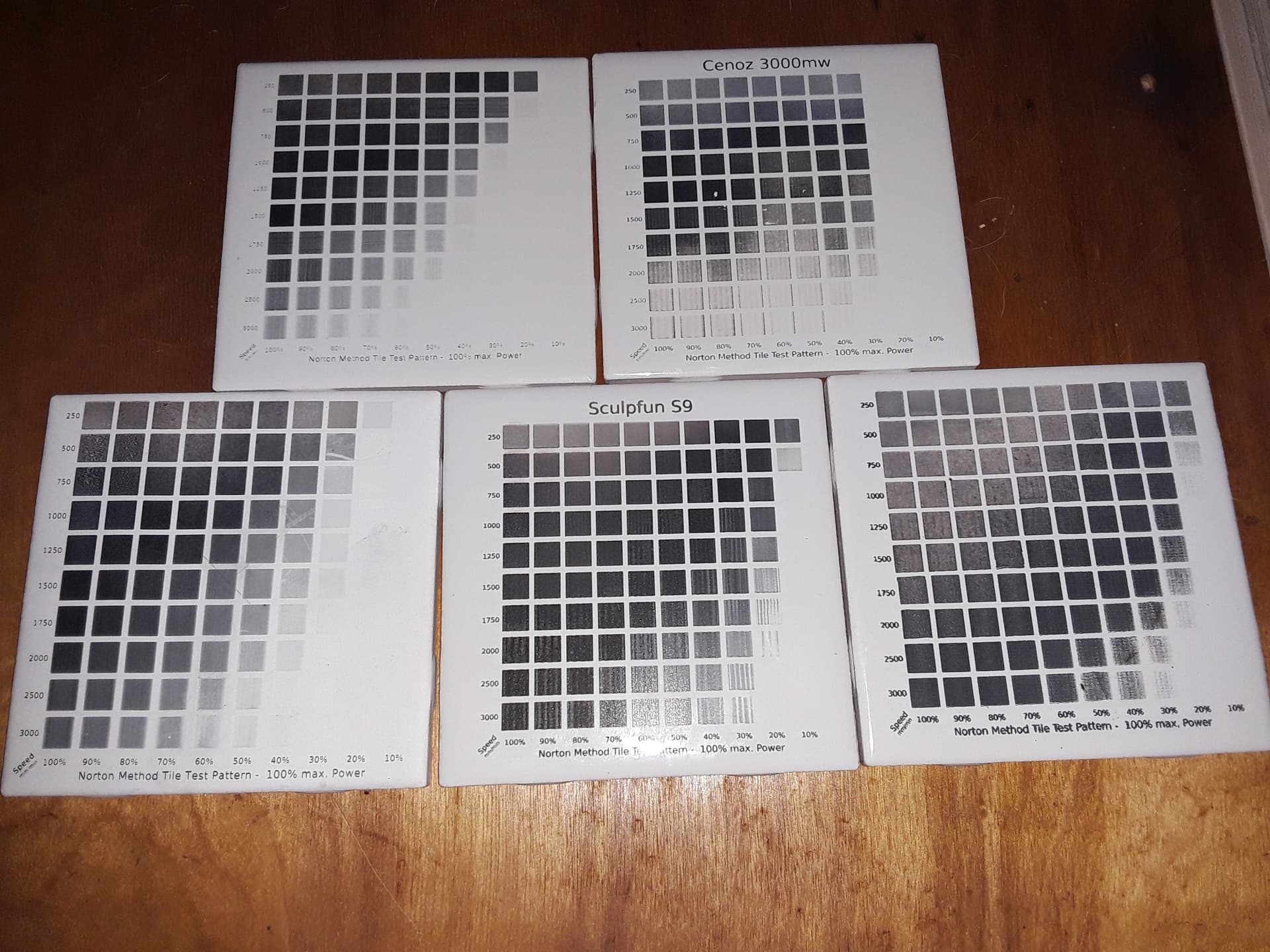
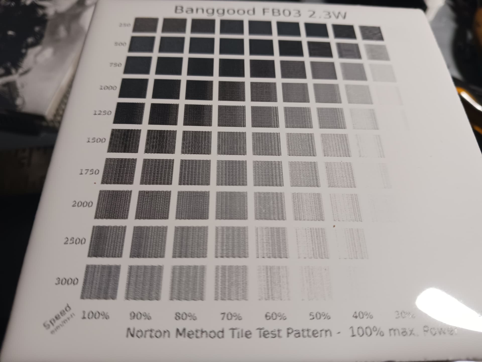
I recommend doing a test tile with your laser and chosen paint… they vary quite a bit. Here are a few test tiles with different lasers… 2.3W, 3W, ~4.5W, ~5W and ~10W (left to right, top to bottom). On each tile, I find the “blackest/nicest black” (note that is isn’t usually highest power and/or speed) and use that speed and power for best results with that laser and paint.
Your 7W laser will do good looking images on tile and glass… you just need to find the speed and power needed to produce the most prominent black. Then, if you’re using Lightburn, you can dial in the “dot size correction” that yields the best detail for your images.
Well, you’ve convinced me. I’ll try to improve upon my current laser instead of buying a new one My images don’t have the details of yours and I don’t think its due to the black part. I have started using the power/speed test since I’ve read one of your posts so the blackness part is relatively on par with what I see in your pictures.
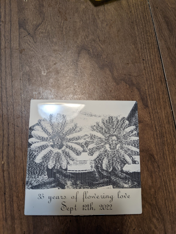
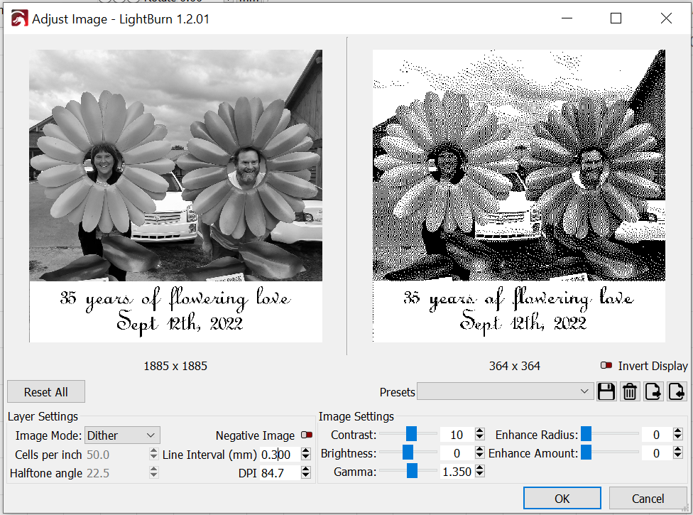
My settings in Lightburn: My image does not have 300 DPI
It looks a lot more like 85 DPI. I looked up the specs on my laser and it has 0.28 mm dot size. Plug that in as the line interval and the adjusted image looks a lot more like reality.
Got any tips?
The other relevant info is that I’m using gcode fan commands for marlin using Ryan’s rampsboard, LCD screen with sd card, and slightly modified V1 firmware to make the fan process correctly (there was a thread on here somewhere describing what was needed, can’t find it now). Not sure if that has something to do with it.
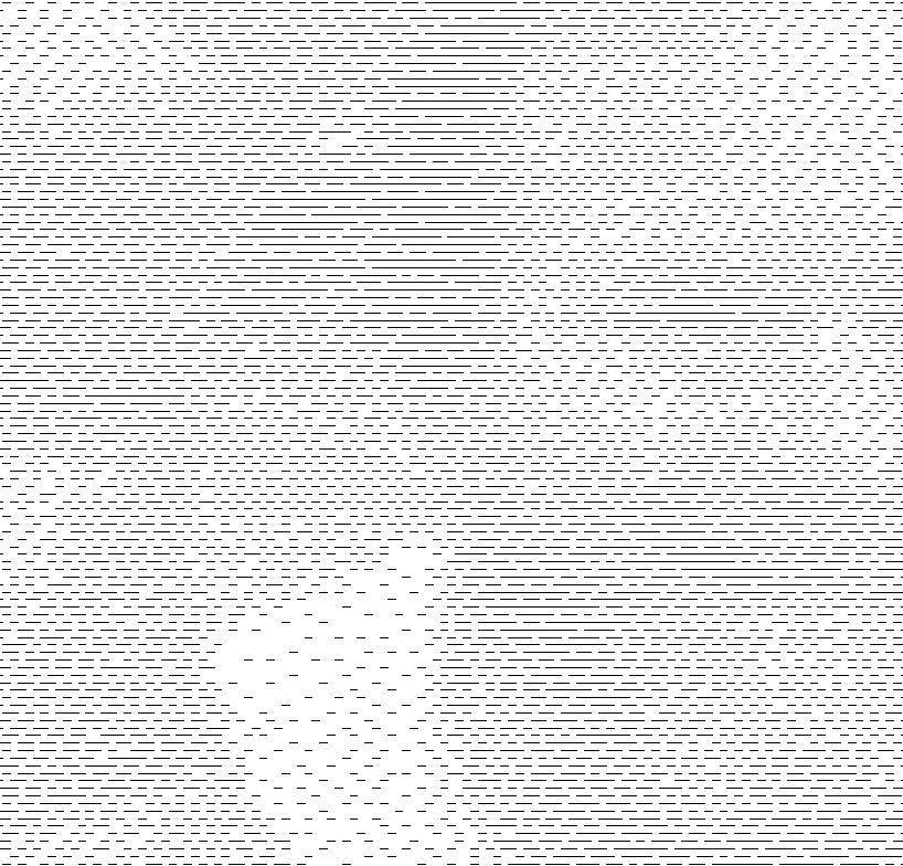
In your picture of all of your test tiles, do you know why there are vertical bands in many of the sample squares? I’m trying to understand mechanically, why that would even happen.
I don’t know why, Robert… but they are always beyond the speed and less the power for what I select as "blackest/nicest black" (after complete paint removal). I this case I determined 1000 mm/min (might of pushed it to 1250 mm/min) and 100% to be my optimal settings…
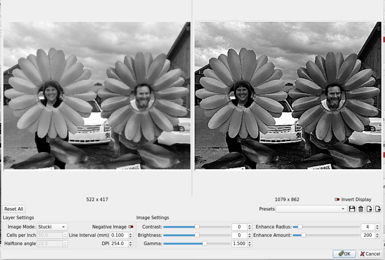
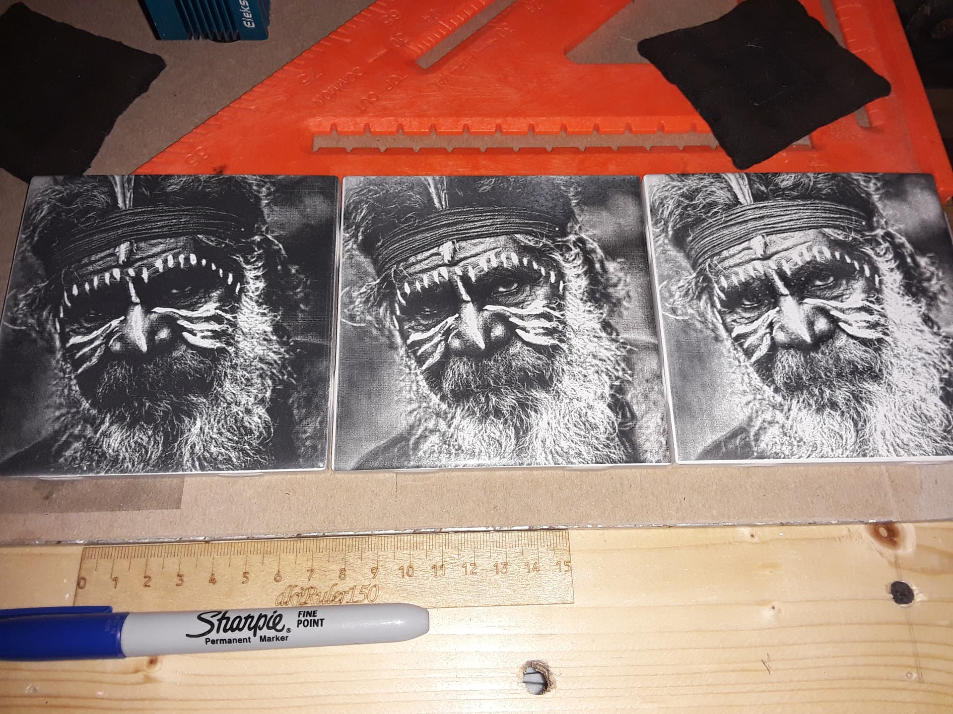
As for @Bigburlybug’s picture, maybe “ignorance is bliss” (talking of me ). I simply captured a screenshot of his original and tried to make it look, what I know by experience, “right on my computer screen”. I’m not scientific about it… just a few moments of work and here are my picture adjustments. If it looks “about right” on the screen, I usually select a dpi between 254 dpi and 339 dpi… and Stucki or Jarvis dither, I adjust contrast/brightness/gamma to suit (shoulda spent more time here), and then add in some enhance radius and amount (4/200) for some “pop”… BTW my “preview” is always quite a bit darker than "reality"…and get something like this…
@Bigburlybug, I don’t know why your tile looks the way it does but obviously 85 dpi is way too coarse. Did you do a test tile and remove all paint before selecting the “best black”? I have no clue where you came up with 85 DPI. As I say, I’m not scientific about it… if it looks decent on the screen, 300 dpi or so usually works for me. Can you take a picture of your test tile? And then we can go from there…
My thinking was that if my spot size is .3 mm, then it wouldn’t be able to make dots smaller than that. Since these pictures are more or less lots of little dots (i think), then having overlapping dots probably isn’t good so the laser should move up one line per dot size (0.3 mm) on every pass. Setting the line interval to the dot size to make that happen calculates out the DPI to be 85 DPI. Thats how I got 85 DPI, but again, I used 300 DPI when actually making my tile.
I looked up glowforge specs (couldn’t find eleksmaker 2.3 details) and it has a dot size somewhere around 0.15 mm but can achieve 1000 dpi so obviously I don’t understand what the dot size spec. actually means, especially since your tile came out so nice.
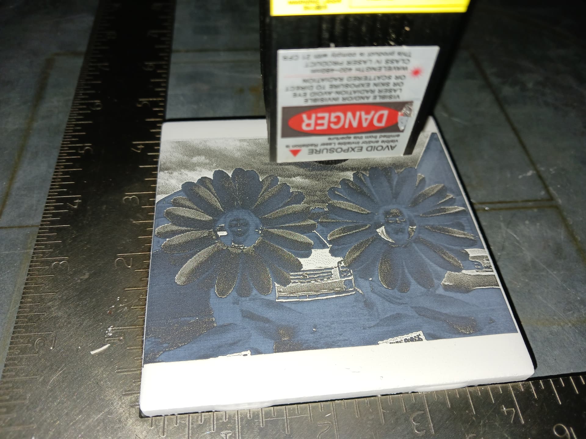
I appreciate the help and yeah, I like the picture too! I did do a test tile, I’ll send a picture along once I get out of work.
See! That’s why I’m not scientific about it… it cuts down on the confusion
Actually, the picture is made up of extremely small line segments… dashes. Here is the “preview” with the settings I used (don’t worry that it’s “not realistic” at this point)…
While a spot size spec may be given, I think the effective beam power is concentrated in the middle and somewhat less than the stated spot size. The NWT test tile is the real proof of what actually goes on IMO. I don’t worry about the stated spot size dimensions on any of my lasers and simply try to get the nicest, smallest, focused spot I can… and this is where my 2.3W lasers “shine”.
That said, Lightburn has a setting called dot-size correction that can help adjust for a larger spot size and bring out more detail… I touched on it back in post #102. The effect of no dot correction on a dithered image is a darker burn and some loss of detail (your “overlapping dots”)… and with dot correction you lighten the image and bring out more detail. That’s clearly seen here with no dot correction (left), 0.02 (middle), and 0.04 (right)
This is why I am confident your 7W laser should be capable of decent looking images on tile, if it is jn good working order. You lost me with your Glowforge statement but, again… I pretty much ignore spot-size specs and trust the NWT test tile to show me what’s possible.
I’m right where you are starting out with engraving. My third test tile is burning now. David’s examples, and all the details he has provided, has inspired me to take the plunge. Looking at your project, one thing that jumps out at me is the low resolution of the source image. According to your Lightburn screen shot, your source image is only 522 x 417, so your project might benefit from a enlargement of that image. Not sure what tools you have to do a quality enlargement, but I bumped into this free website, which throws 4 different algorithms at the enlargement and lets you select the one you think is best.
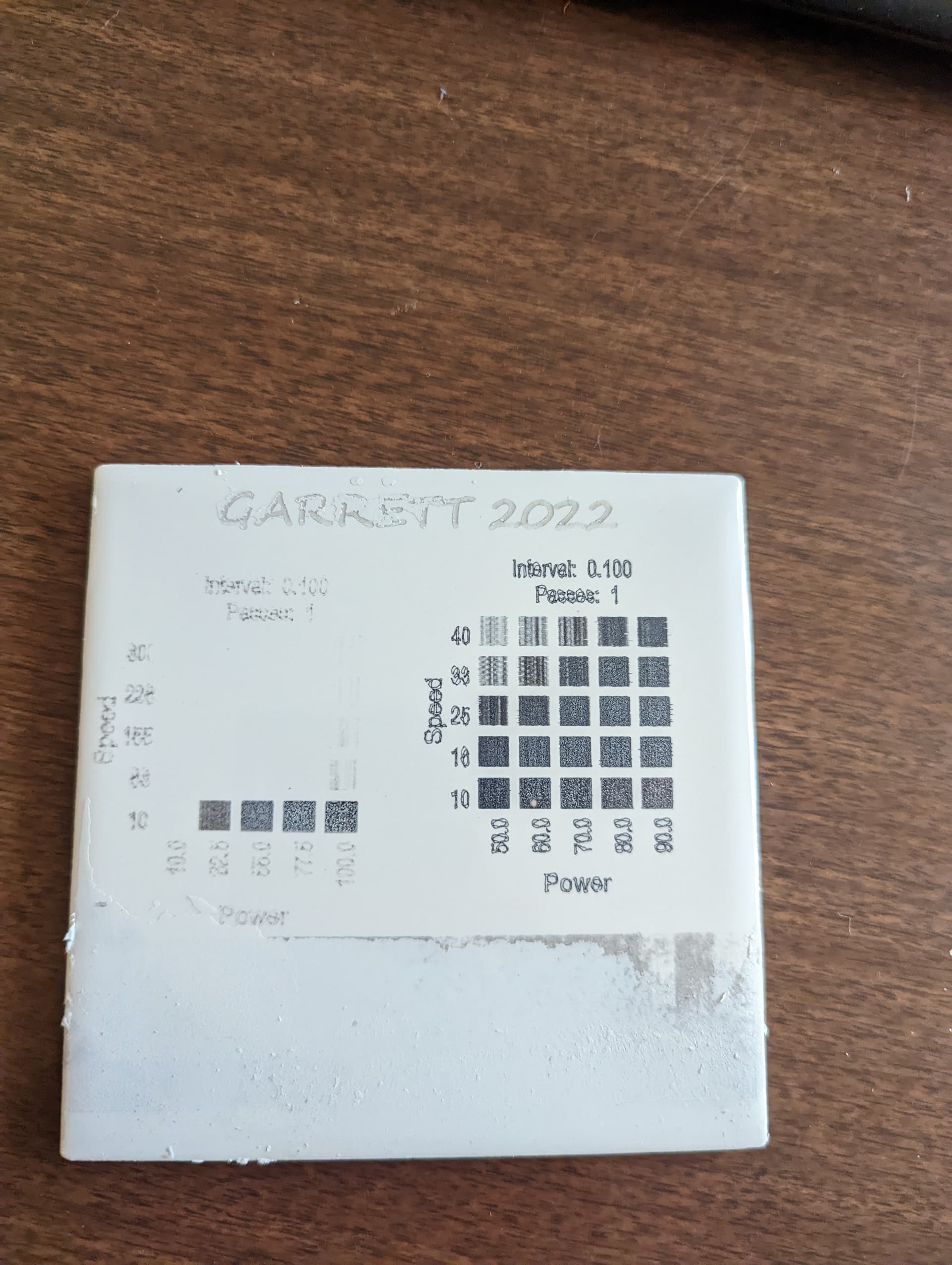
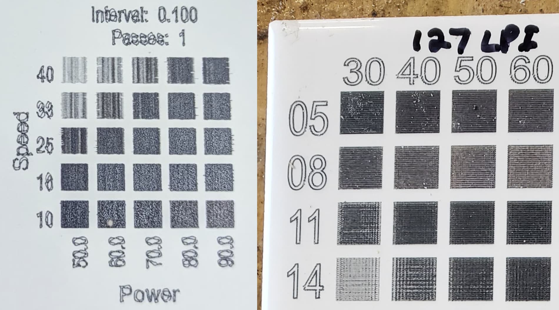
Here’s my material test. I choose 26 speed and 50 power hoping the vertical lines would go away oncr the laser had a longer running path (nope!)
I’m using a laser height tool that came with the ladder to set the focus, wondering if that might be an issue. I’m out of town this weekend so I’ll check that afterwards.
Robert, I would argue that David’s tile, which looks awesome, was a screen grab of my picture which was already low resolution. So scientifically, his picture should come out even worse than mine. But being scientific isn’t working out for me so I’ll try that out anyways lol
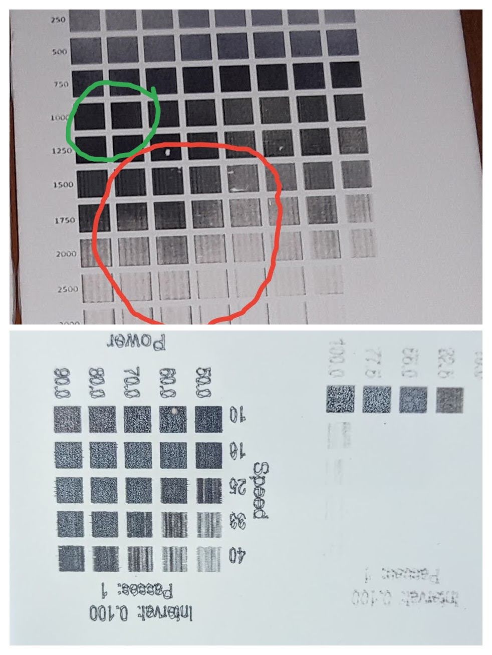
That really doesn’t look right. We really need to see a larger range of power/speed… on my test tiles you should see the “best blacks” will run roughly diagonally from “upper right” to “lower-left” similar to these
Looking at the collage below, your test grid (bottom and flipped) looks to be more like the RED circled region in mine… which is both too fast and too little power, relative to the GREEN circled area that I think would yield a “best black”; i.e. below and right of the “diagonals” in the tiles above.
And I guess we need to determine what units you want to work in. You said you chose “26 speed”… is that in “mm/s” (1560 mm/min)? If so, 1560 mm/min and 50% power would indeed be in the RED circled area.
Also, what paint are you using to coat the tile? A flat-white paint from Rustoleum or Krylon is generally a good choice… but they do vary a bit in TiO2 content (the “magic” ingredient*).
The “vertical lines” in the test blocks don’t go away… they seem to consistently be in areas of "too fast" and/or "too little power"…
Also, the lettering on your tile looks a bit “squiggly”… is your machine “loose”/sloppy in any way? Does it do better if you slow down?
I assume “a laser height tool that came with the [laser]” is a step guage of some sort. That’s probably not a real problem unless you’re unsure about which step you should be using for best focus. But your test tile seems to appear reasonably well focused to me.
Please try this NWT grid test file so we’re doing an “apples to apples” comparison (we can work out the units later)…
I believe you have a significant mechanical issue with your machine. Here is a side-by-side comparison of your test grid and a section of one of my test tiles. Look at the lettering.
My letting and your lettering are approximately the same size. And while I have a few artifacts in my lettering, your lettering has lines wandering over each other. This issue is really obvious in your original photo. This problem would account for your noisy squares since you cannot depend on your machine to evenly paint the squares. I suspect looseness in your Z axis as the cause. I had some loosness in my Z axis a while ago and traced it to cracked/broken core clamps.
Yeah, that makes sense. I’m mounting the laser to my 4 foot lowrider 2 and I definitely went more for build speed than accuracy telling myself I’d rebuild it once I could use it to make better parts (2 years later and still original). Printing out some new pieces now and will re-mill the wood parts since they’ve become bowed. I’ll try again with the laser next week after the rebuild.
Nice looking test, can’t wait to see your pictures!
I’ll try this out while everything is printing.
You are correct but there are no steps, its just piece of plastic that’s the proper thickness for the focus, no steps.
At some speeds, I was having similar problems to yours in terms of the beam wandering. I tracked it down to my acceleration settings. I had increased them in order to increase the speed of my machine, but they introduced the issues that are similar to what I see in your photos. I put them back to V1 defaults, and all wandering lines went away.
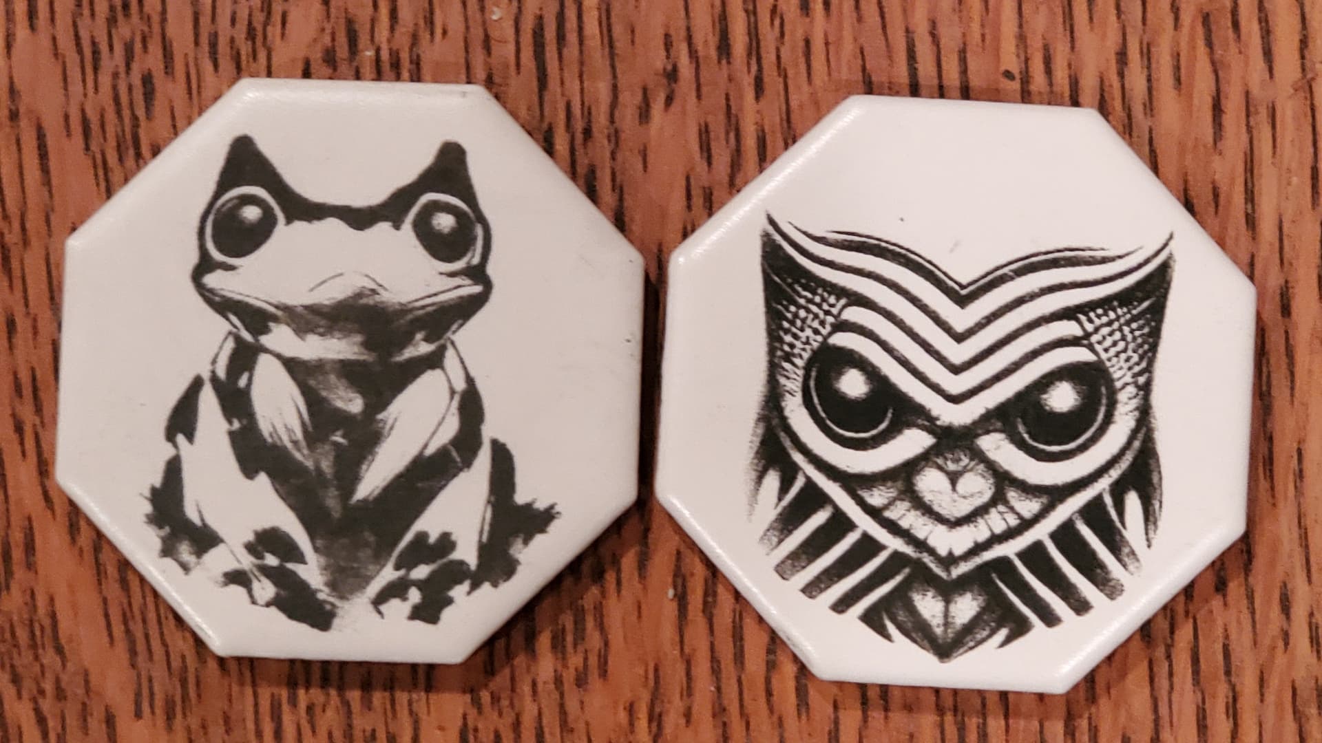
As for burning tiles, I’m still struggling. Anything that is largely black and white with minimal shading is fine, but when an image depends on having shades of gray, I end up with something either too dark or too light, and have not found the magic settings that are “just right.” Here are a couple of small tiles from today:
I’m still tempted. Not sure I’m gonna be able to get my lowrider dialed in enough to do small picture laser work. Did you have to reflash the board or anything to get it to run gcode from lightburn (or whatever software you’re using?)
I did not buy it. I am only passing this along. I got possibly the last of the 79 dollar ones. And yes i followed the 2 posts above. One to flash grbl the other to set proper settings.
Just a FYI… I’ve got my original $79 Centoz machine ready to deliver to my friend. The original JL1 controller was successfully flashed to GRBL 1.1f using just a Windows computer and @LsrSal’s original firmware download (w/ updater.exe and ROM.bin). I added a printed Z-lift mechanism and modded it to use a couple of different lasers. I’ve used it in this thread to show its capabilities on a number of different materials and even demonstrated its use with Xtool’s RA2 rotary accessory.
This morning, I unboxed the second of these $79 laser engravers (the one I’ll keep…) and have successfully flashed GRBL 1.1f using the exact same procedure as before. My plan is to replicate my friend’s machine and so far I’m still impressed. I wish it didn’t require any “loving touch”/“sweat equity” to make it really useful but if a person is willing – and a little bit “handy” – it can be a very fun, educational, and satisfying project for not too much $$$.
It’ll be interesting to see how long those 11 machines last out on Amazon…
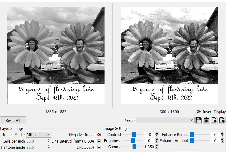
 ). I simply captured a screenshot of his original and tried to make it look, what I know by experience, “right on my computer screen”. I’m not scientific about it… just a few moments of work and here are my picture adjustments. If it looks “about right” on the screen, I usually select a dpi between 254 dpi and 339 dpi… and Stucki or Jarvis dither, I adjust contrast/brightness/gamma to suit (shoulda spent more time here), and then add in some enhance radius and amount (4/200) for some “pop”… BTW my “preview” is always quite a bit darker than "reality"…and get something like this…