I’d rather see most of the extras controlled via g code as much as possible. I know diodes are voltage sensitive in general. But it should be a really sharp curve. I also know that my 1.6W laser has some method of turning the power down other than just pulsing because it has a low power focus mode that is not powerful enough to feel warm…
I would think PWM would be the best control. It would be great if it could support 5VPWM or 12V differential PWM. The fan output on these boards is 12V and low side drive. Meaning the negative switches between ground (on) and floating (off). Analog output is achieved with PWM out so pulse width is more accurate, AFAIK.
If you want to add an “aiming” mode, I would consider a separate switch. In the new laser mode in grbl and I think in Marlin, the power is proportional to speed. So it turns off at zero speed. Having a separate aim power switch would let you skip that whole problem too.
Make sure, as best you can, that unplugging something turns stuff off. You don’t want it accidentally going full power on a loose cable or a mistake in the wiring.
1 Like
I hadn’t really planned on too many extras, aside from maybe mapping PWM to some kind of Analog/PWM combo. So maybe 1% PWM input would translate to 100% duty cycle, but only 1V going into the blackbuck, which for a 7W laser would be less than 1W of output. Then aiming mode from g-code could be accomplished by sending a very low setting. After that, it would map as normal. Not sure how I can accomplish this yet. I would need to read the PWM from the controller, and translate it according to my needs. Not sure if the increased delay would matter, either. Need to do some testing.
L-cheapo has a schematic to solve that issue. Not sure how it fails if disconnected. Search for “ramps” on that page and they talk about it. LCheapo | Robots Everywhere Wiki
One of the features of the Jtech is a fail safe if there is a power cycle. I was thinking of having an arm switch that would need to be pressed before the laser would fire. That way if it the unit is turned on accidentally, or there is a power cycle, it will fail safe. Maybe a timer that disarms it if there is no input for a while. Also have a manual aiming button. I would expect these features to be part of the arduino I talked about in an external box, not on the main laser unit.
1 Like
The link seems to be broken.

I did some testing on reading a PWM signal on an arduino. It’s doable setting interrupts on the input pin, then measuring the pulse. It seems to be fast enough so that there would only be a delay of one cycle. So at 500Hz, the delay would be around 2ms. If the MPCNC is traveling at 20mm/s, that’s 0.04mm or 0.0015in. I don’t think that would have any noticeable effect in the quality of the output. I was burning images at 250DPI, and that is less than that.
In order to change the voltage of the output, that’s a little trickier. I think if I took the PWM output through a voltage divider, than back to an arduino pin, I could change the non-PWM pin from input mode (basically floating) to output mode and drive it low. This would effectively give me a PWM output I could change the peak voltage of with another pin. This isn’t tested as I really need a scope to see it. I have a DAQC2plate for the Pi that can act as a scope, but the software is a little lacking (but the hardware is great). I don’t feel like fighting it today. I keep telling my wife I need an oscilloscope. Seems like I need one to verify everything 
But that got me to thinking - why not just put a small capacitor and a pull down resistor on the PWM output and basically convert it to analog? It’s been a while since I took an EE class, but at 5V a 0.01uF capacitor and a 10k resistor should give a discharge rate around 0.001 sec. (OK I cheated and used an online calculator I found).
I need to do some tests, but that will probably wait until next weekend. I have a few jobs to crank out on the laser before I tear it apart.
1 Like
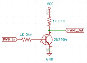
I found something similar and had it working on a RAMPS board I was testing with my laser.
http://blog.eccentricworkshop.com/grbl-pwm-inverter-circuit/
1 Like
There is a pulsein function to measure the width of a pulse (I think it is absolute, not a fraction of duty cycle). I don’t know how pressed for time you are, but I think it essentially polls for both edges.
Putting an interrupt on both edges is the right way to measure it.
How long does the analog input take? I remember it being relatively slow. What speed is the pwm coming out of Marlin? You would want the LPF to smooth it out enough to not sag much in between, but fast enough for the application. 1ms while traveling at a speed of 10mm/s, it would be a delay of 0.01mm. at 100mm/s, 0.1mm. That would be fine with me, but I am not sure it is slow enough to keep a steady signal. If it was a 1kHz signal, it would have a 1ms period, and it would drop a lot in the half period between high and low.
Ryan worked some of this out in the pid speed control code he wrote.
Thanks for that. It looks to be a blocking function, but it may be more reliable than what I tossed together for testing. Even if it’s blocking, it might still work OK. I would need to use the timeout, and if a pulse isn’t found, I need to default to the pin state (low or high).
I found this as a basis for reading with interrupts:
https://www.benripley.com/diy/arduino/three-ways-to-read-a-pwm-signal-with-arduino/
Which analog input? The analog input into the laser driver?
I think the intent (at least with a higher power laser) is not to smooth it out perfectly, but just get the PWM to average out a little more so the lows are a little lower. Before I get to far, I’m going to run a couple of manual tests of 0-100% PWM, and 0-5V analog across a gradient line to see if I can even tell the difference. If I can’t see a difference, there really isn’t a need to mess with analog.
If anyone knows of any materials that might make this test be more obvious, let me know.
That’s great! I’m hoping to do build the whole thing from parts, but that is really great if you have an off the shelf laser. I’ll probably print one just to have something I can hold and see how the sizes work out.
So here’s where my experimentation has led me this week.
TLDR: I need a better heatsink.
I pulled the Endurance off the MPCNC and did some bench testing. The first order of business was measuring the stock current, which is more difficult than one would think because it uses a constant voltage driver. So as soon as I stick my amp meter in, the voltage (and current) drops. So I measured the diode voltage before, then put the meter in, then increased the voltage to the diode so it was receiving what it was when stock.
| Laser Diode | A | V |
|---|---|---|
| stock | n/a | 4.6 |
| w/amp meter inserted | 2.25 | 4.23 |
| after V adjusted back to stock | 4.13 | 4.6 |
| at spec 4.9A@4.75V | 4.9 | 4.7 |
So out of the box, the laser current would have been slightly below the specification card that came with the laser, but not by much. At this point I have not validated the output power, as I do not have a laser power meter.
A warning about constant voltage drivers
Here is why you don’t want a constant voltage driver: I removed the cooling fan while on the test bench to see what would happen. Within a minute, the heatsink temp rose from 100degF to 110degF, and the current increased 100mA - then I shut it down quickly. With a constant voltage, more heat = more current, and the cycle continues until bad things happen.
Start of Heatsink Experiments
From here, I wanted to start experimenting with heatsinks, as that seems to be the critical part of the design. I swapped in a constant current driver, and made some measurements.
Test 1: Stock heatsink and fan
So here are some tests on the stock heatsink and fan:

After a few minutes, things level out and it seems to dissipate heat well.
Test 2: 12mm bearing mount
My first DIY attempt was with a 12mm linear bearing mount that looks like this:

Not good. The temp keeps climbing, and the voltage keeps dropping because it is maintaining the constant current. If the voltage were fixed, the current would have kept going up. Note that this goes beyond temperature “spec” for the NUMB44. I say “spec” in quotes because I have yet to find a real spec sheet. Most information states 60C/140F max. I think the heatsink temp is a little low as compared to the FLIR because it is below the driver (under the kapton tape in the picture).
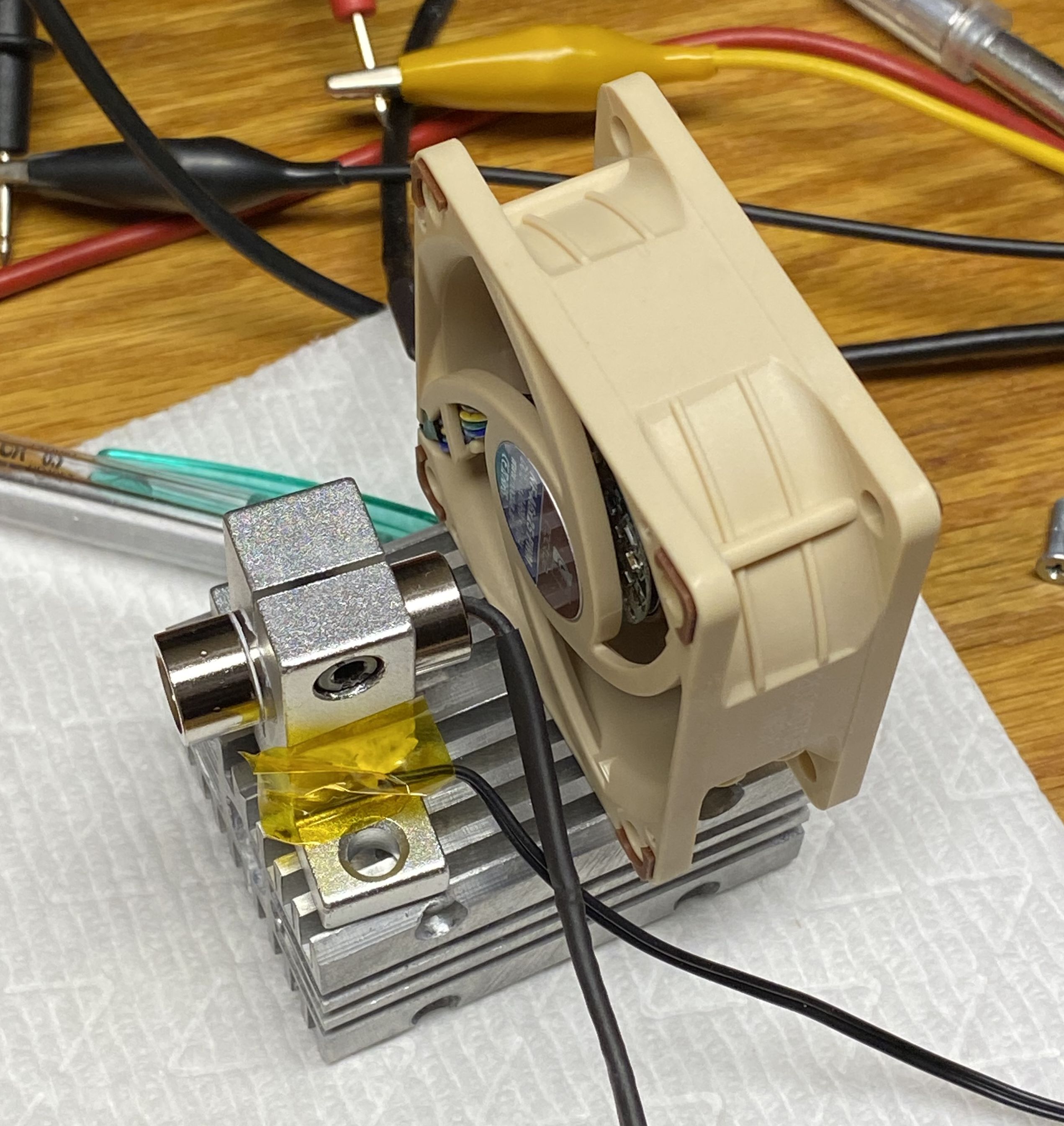
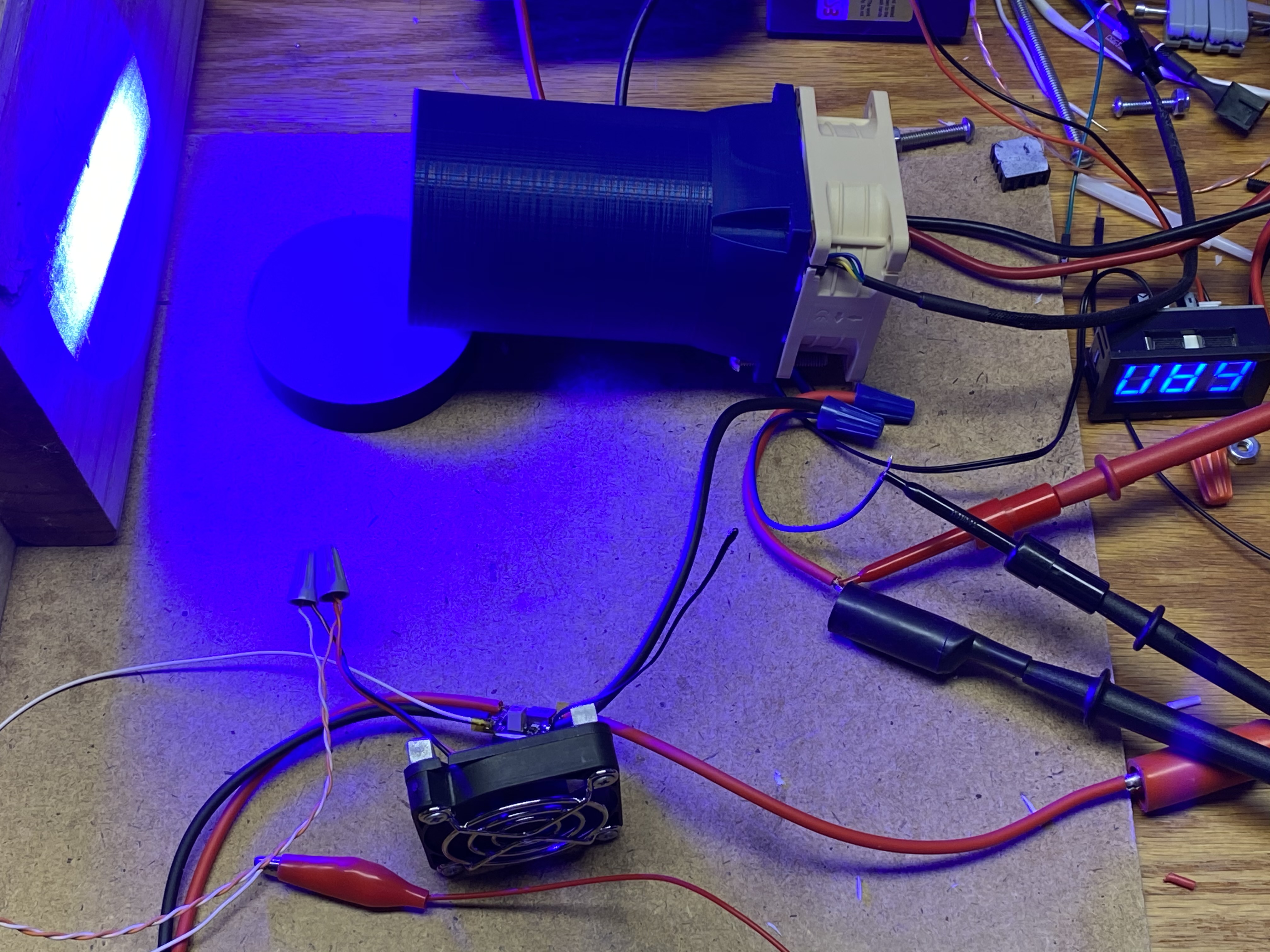
Test 3: 12mm bearing mount with heatsinks and better airflow
So after sleeping on it, I stuck some heatsinks on the bracket. I was doubtful it would work, but to my suprise it did. Here’s the modified mount:
And improved airflow during testing: (you can see it inside the square tube)
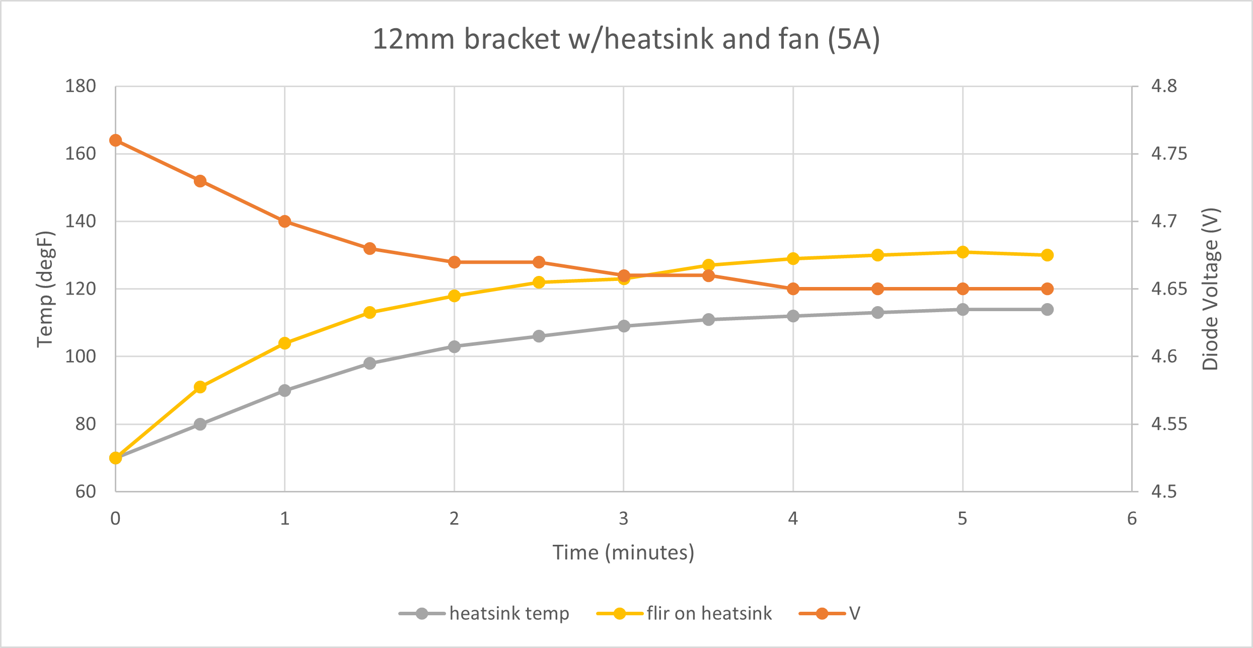
While this did maintain temperature, it definitely wasn’t as good as the stock heatsink. I did change two things in this trial (heatsinks and airflow), but I think the heatsinks had much more to do with it.
Summary and next steps
I think all of the components for a DIY 7W laser are easily acquired, aside from the heatsink. My crappy heatsink does lead me to believe some of the smaller 12mm laser heatsinks might be good enough with a strong airflow. However, I don’t like how the laser module slides in and mushes all the thermal grease out, then its just held in with a set screw - I can’t image that has good thermal conductivity. But for a few bucks, I will order one and give it a try.
I am aware there are many heatsinks like in the Chinese lasers on Aliexpress and the like. My hope is to find something you don’t have to wait so long for.
2 Likes
Have you tried using a cpu cooler?
I could stick the 12mm mount I have to a cooler, but I’m thinking there would be too much mass between the diode and the cooler. I thought about cutting off the bottom bracket so it is smaller, but I don’t have a CPU cooler laying around either. I didn’t spend too much time thinking about it since the result probably wouldn’t fit in a 65mm tube.
I did find this heatsink last night. It’s a similar size to the stock cooler, so I’ll give it a try.
https://www.z-bolt-laser-systems.com/hs-1a-12mm-heat-sink
I realise it is probably too late as you already have most of your hardware sorted but I would recommend you take a look at the NEJE range of laser modules. They incorporate the laser diode with the heatsink, PWM C.V. control board and the cooling fan in one neat unit. They do a claimed true 7.5 watt optical power laser unit. All of their range also incorporate a thermistor integrated onto the laser diode (so minimal thermal gradients) and details of the simple divider network and temp/voltage tables enabling you to write a sketch to auto control the fan if required. There is also a separate 'control board that has a 3 digit readout for temp and pwm input. https://neje.shop/collections/neje-laser-module-head-diy-kits-for-wood-router-3d-printer-and-cnc-laser-machine/products/30w-laser-module-laser-head-with-pwm-tester-for-cnc-laser-engaving-cutting-machine-wood-marking-cutting-tool
You might find some interesting stuff there.
1 Like
Thanks for that. I did see those on ebay, but it’s nice to have a link to their main store. Here’s a table of lasers I have looked at so far. Most are in the 6-10W range, but I’ve included a few other common options too. I scrubbed the forums a bit for others, but I’m not going to include all the random banggood/amazon/aliexpress options. They seem to fluctuate a lot.
If you asked me today to buy a ready-to-burn laser, I’d go for the one from Barnett Unlimited on eBay. Nice design, known diode, big fan, diode protection, and seems to be well respected over at laserpointerforums.com (Shmackitup)
| Description | Stated Output Power | Price (USD) | Notes | Link |
|---|---|---|---|---|
| OptLaser PLH3D-6W Hobby | 6W | $449 | laser head only | OptLasers.com |
| OptLaser PLH3D-6W-XF | 6W | $549 | laser head only | OptLasers.com |
| L-Cheapo MK7 | 10W | $300 | laser head only | robots-everywhere.com |
| Barnett Unlimited | 7W | $250 | laser head only | ebay.com |
| NEJE 30W Laser | 7.5W | $119 | complete kit, 30min max run time | neje.shop |
| SainSmart | 5.5W | $150 | complete kit | amazon.com |
| J-Tech 7W | 7W | $700 | complete kit | jtechphotonics.com |
| J-Tech 4.2W | 4.2W | $550 | complete kit | jtechphotonics.com |
| J-Tech 2.8W | 2.8W | $410 | complete kit | jtechphotonics.com |
| Endurance 10W | 10W | $595 | complete kit | endurancelasers.com |
| Leo Laser | 2.8W | $100 | DIY Kit | v1engineering.com |
2 Likes
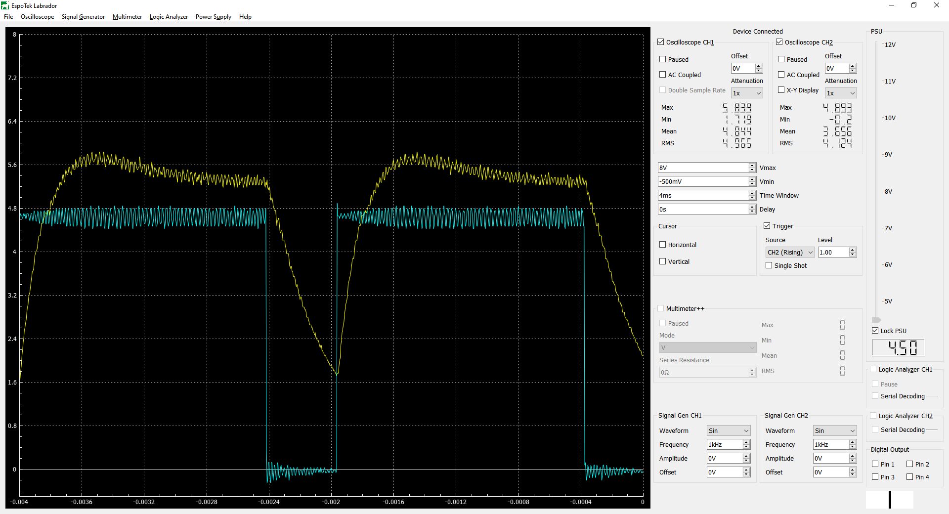
My EspoTek Labrador was delivered early, so I got some tests in with the scope today. I don’t really know what I’m trying to accomplish with this particular test. Just curious how the diode and driver behave.
Disclaimer: I am not an expert on the operation of these drivers or diodes. I’m just observing and hypothesizing for my own knowledge. If I state something incorrectly or if you can provide more insight, please let me know.
Setup:
- BlackBuck 8M
- 5A current setting
- PWM driven from an arduino
CH1 = Diode Voltage (yellow)
CH2 = PWM Out (cyan)
At low duty cycles, it isn’t strictly an on/off at full power. I hope this will alleviate my issue of still burning the work piece at low power while aiming with the stock driver. That one really had a hard on and off since it was just switching the full voltage on and off.
About 2-3%:
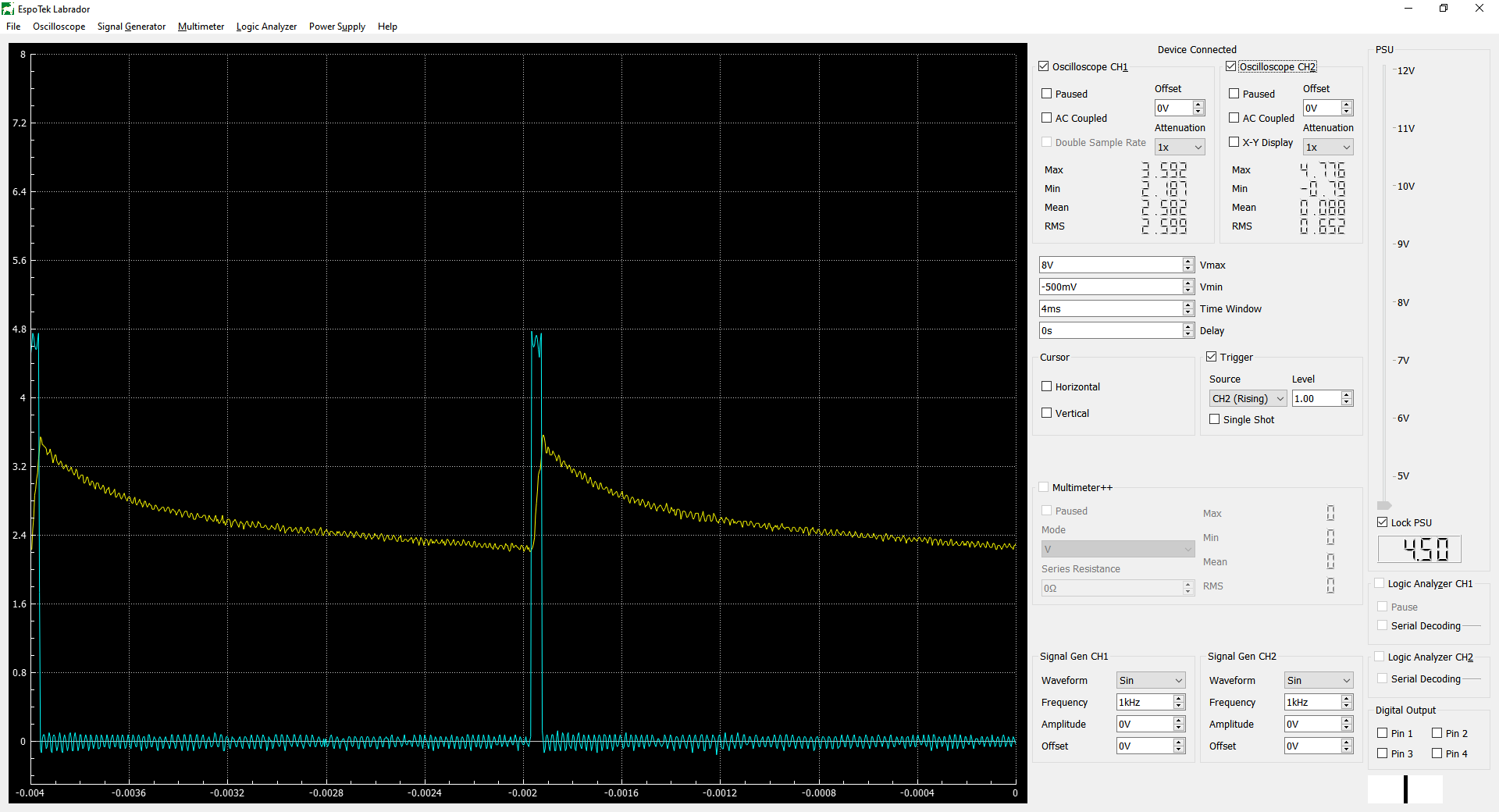
About 7-8%:
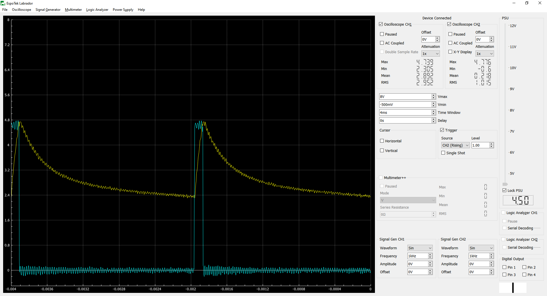
About 35%: This one is interesting becuase it’s overshooting a fair amount. The diode Voltage at 5A continuous is 4.7V. This is peaking at 6.2V.
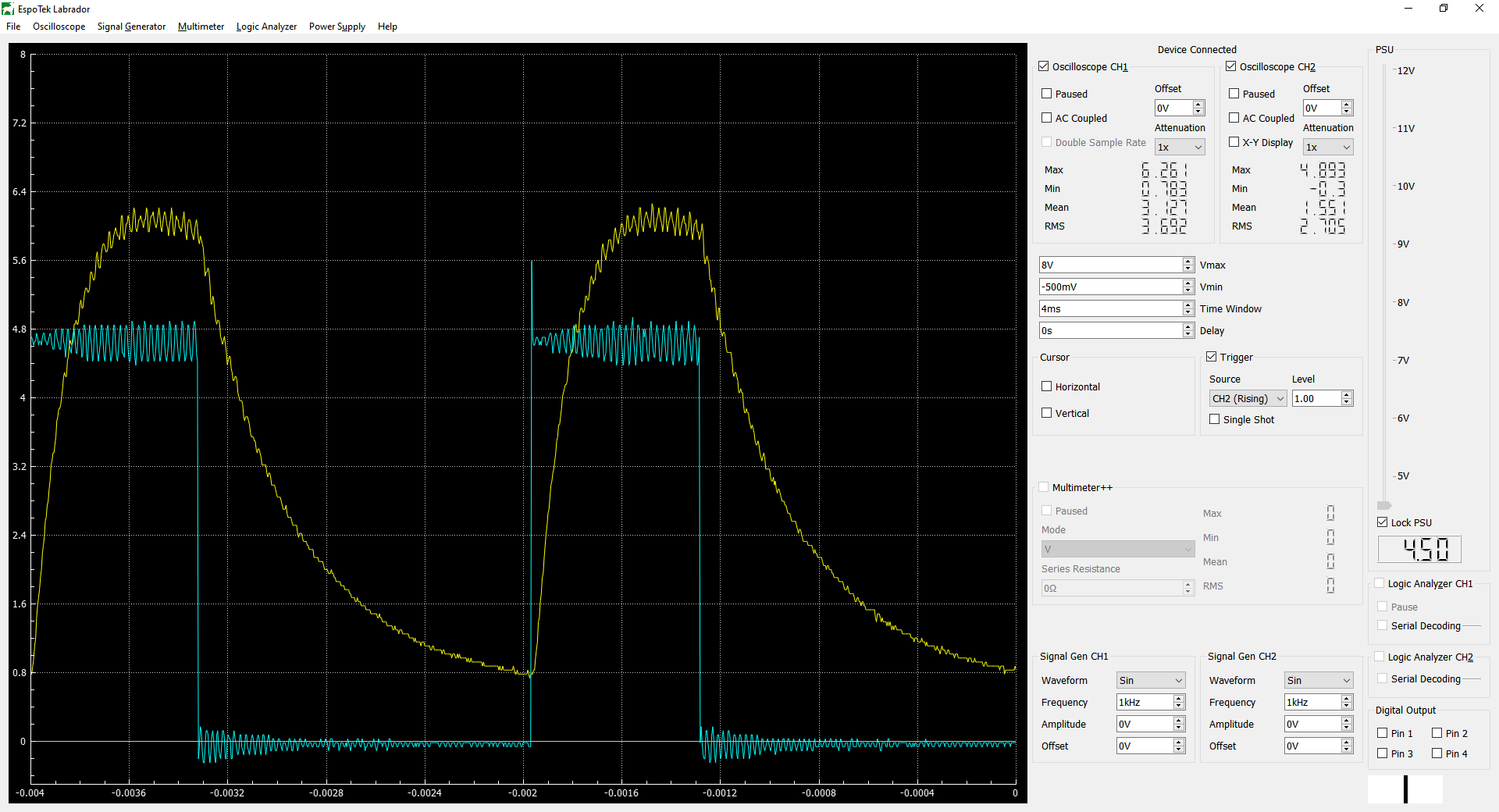
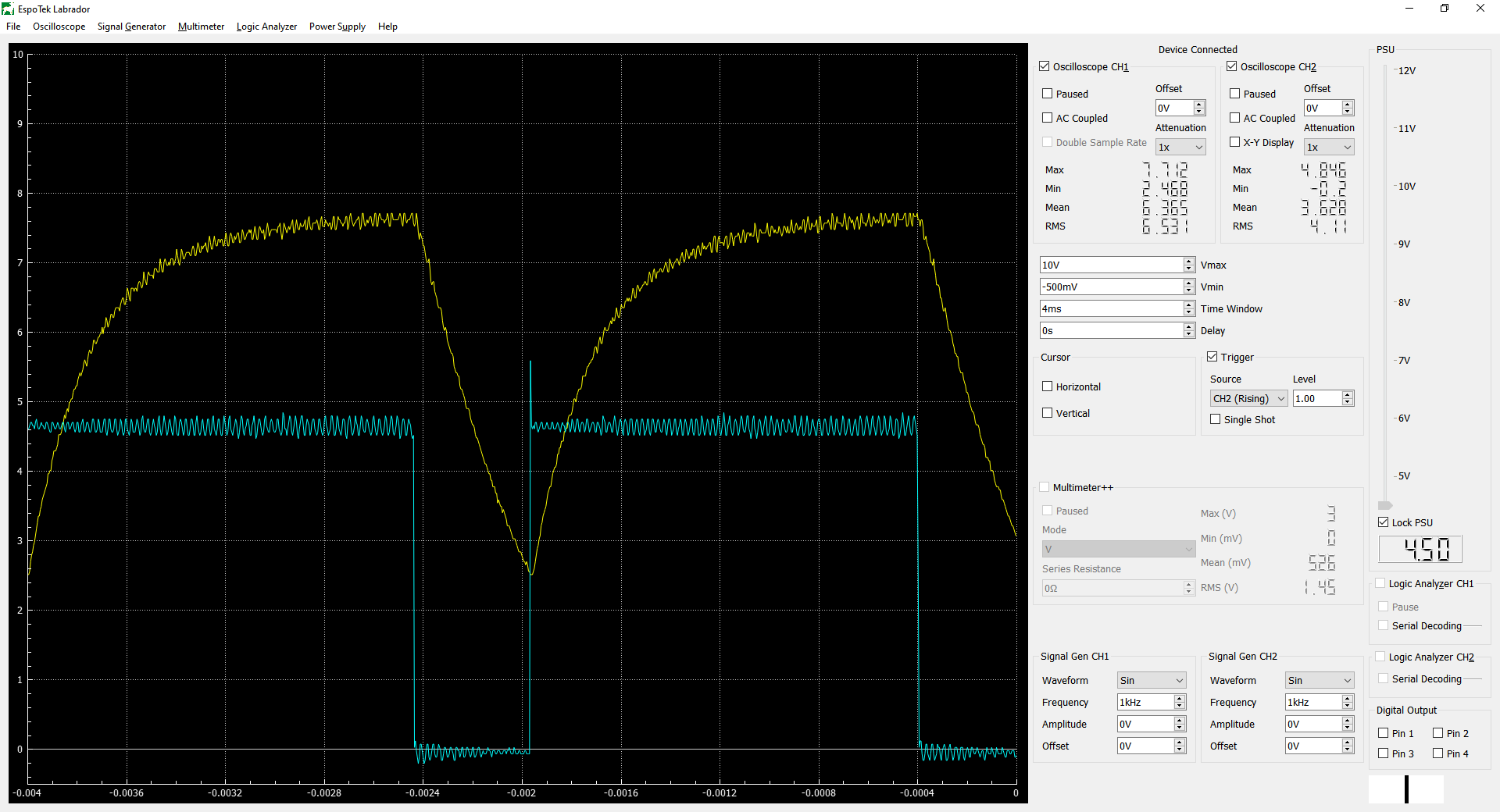
About 80%: This one is not over shooting as much as the prior test. Peaks at 5.8V and averages out around 5.3V before the cycle starts over. This pattern goes away as you approach 100%.
I was curious what the current was doing so I put a 0.1ohm sense resistor in line to see what that looks like. It’s super noisy, but you can kind of see the same pattern. Triggering wasn’t working well due to noise, so I widened the time a little to 20ms across the screen. The scope shows the voltage drop across the sense resistor. V*10 = A
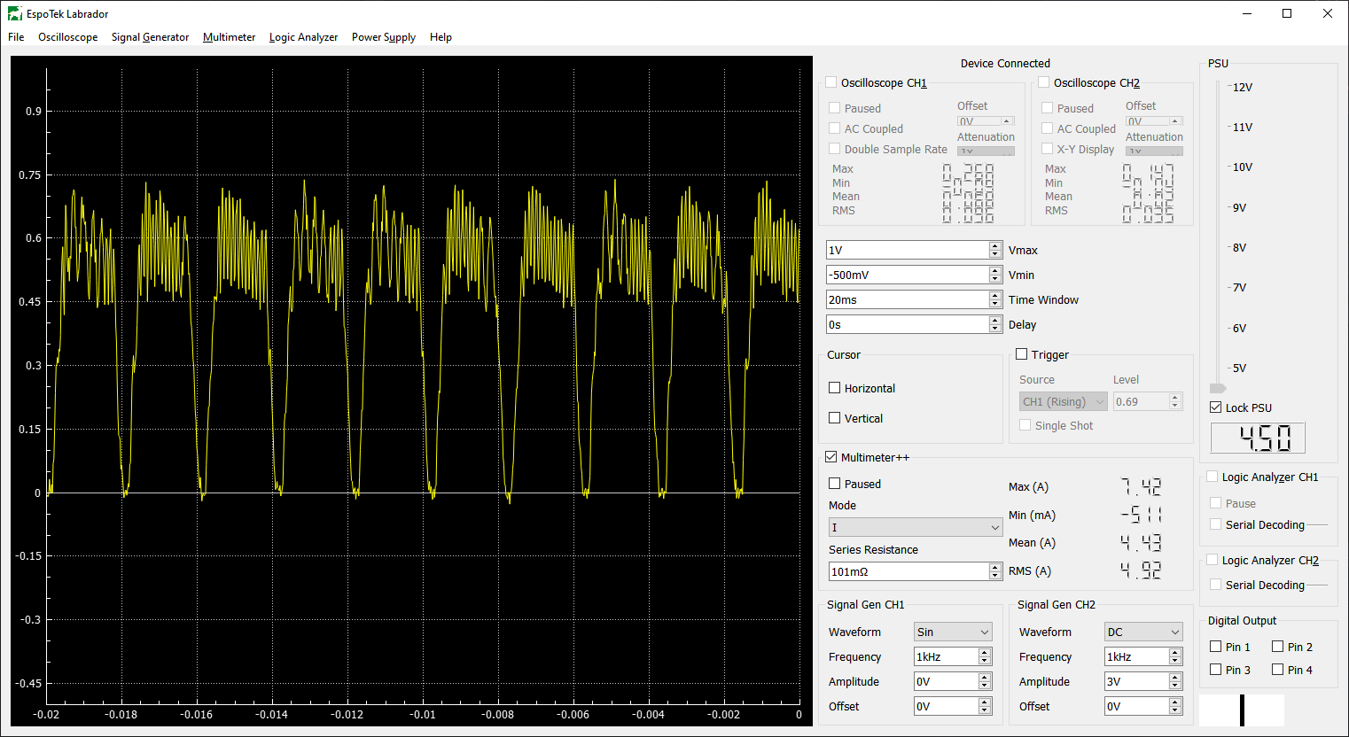
I think this overshoot is a characteristic of the diode, rather than the driver. Using a purely resistive load, there is no overshoot. However, a higher voltage is needed to get to 5A, and closer to the 12V input to the driver, so that might have something to do with it.
I would hypothesize that most constant current power supplies overshoot a little when they first come on. The ones I have looked at use a sense resistor at the output to adjust the voltage being delivered to achieve the desired current. Being relatively analog in nature that will take time to reach equilibrium.
2 Likes
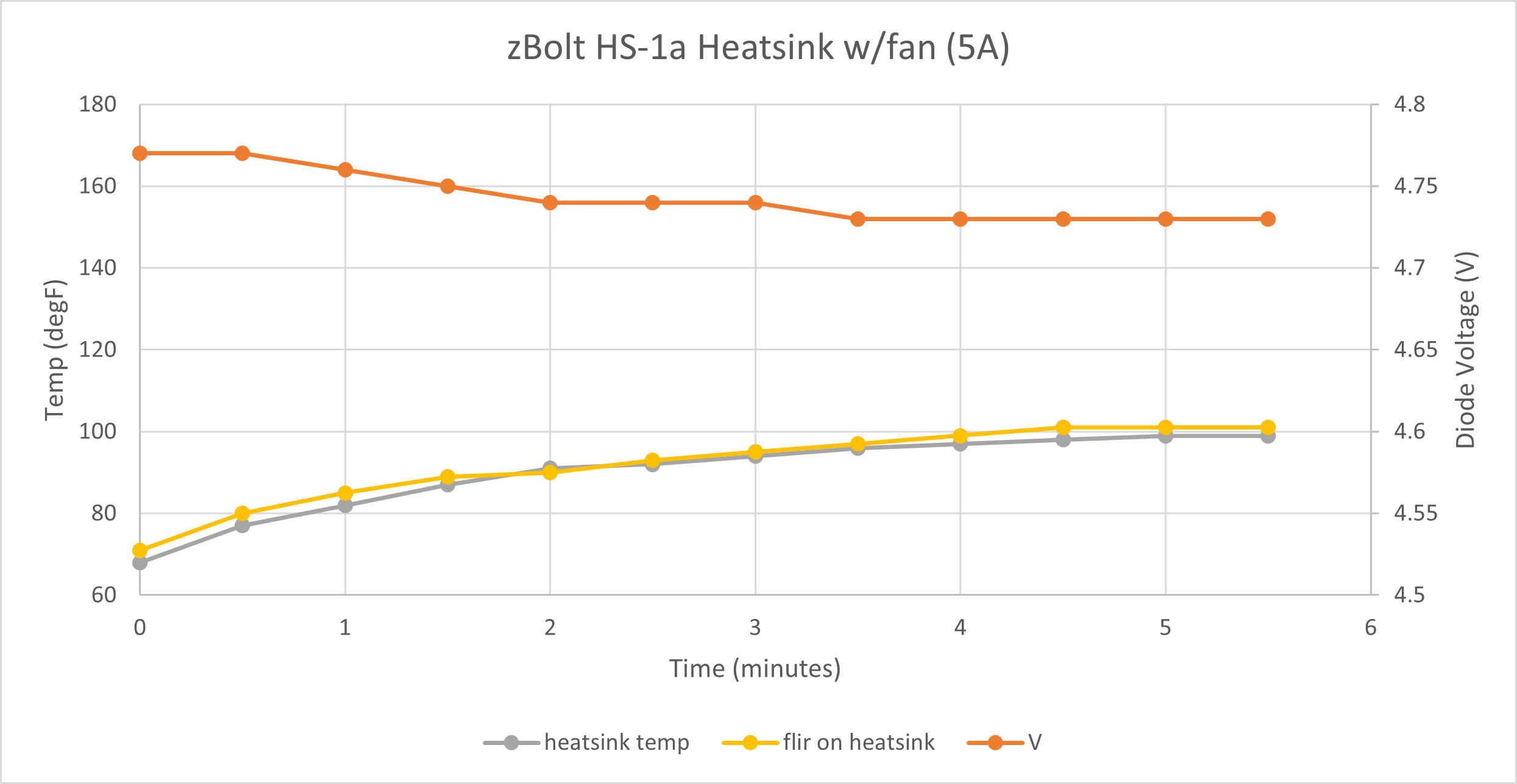
I got the Z-Bolt heatsink and did some tests.
Electrically, the test setup was identical to the previous ones. Voltage and temperature over time are much more like stock. I would have no concerns running this for long periods of time.
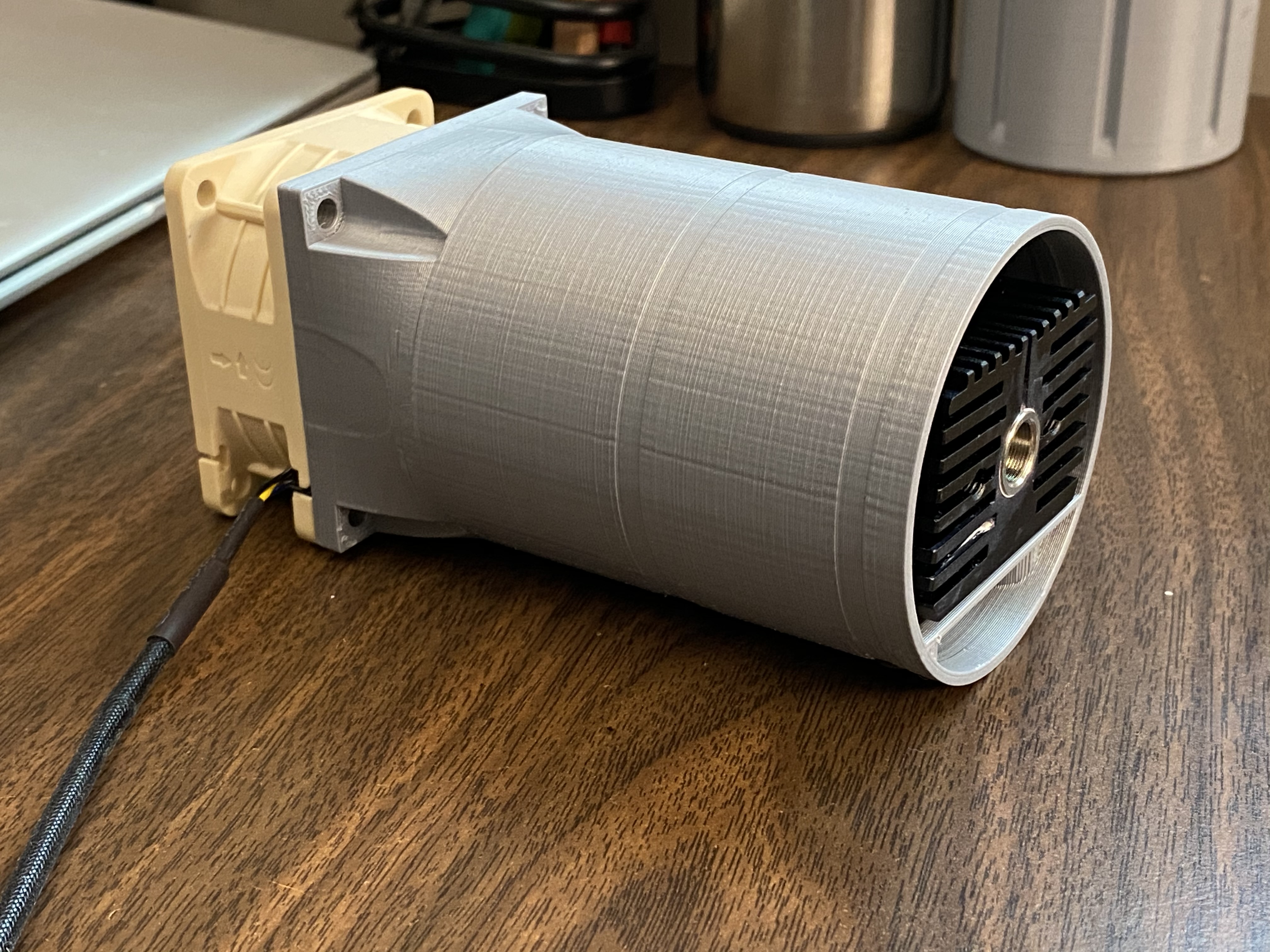
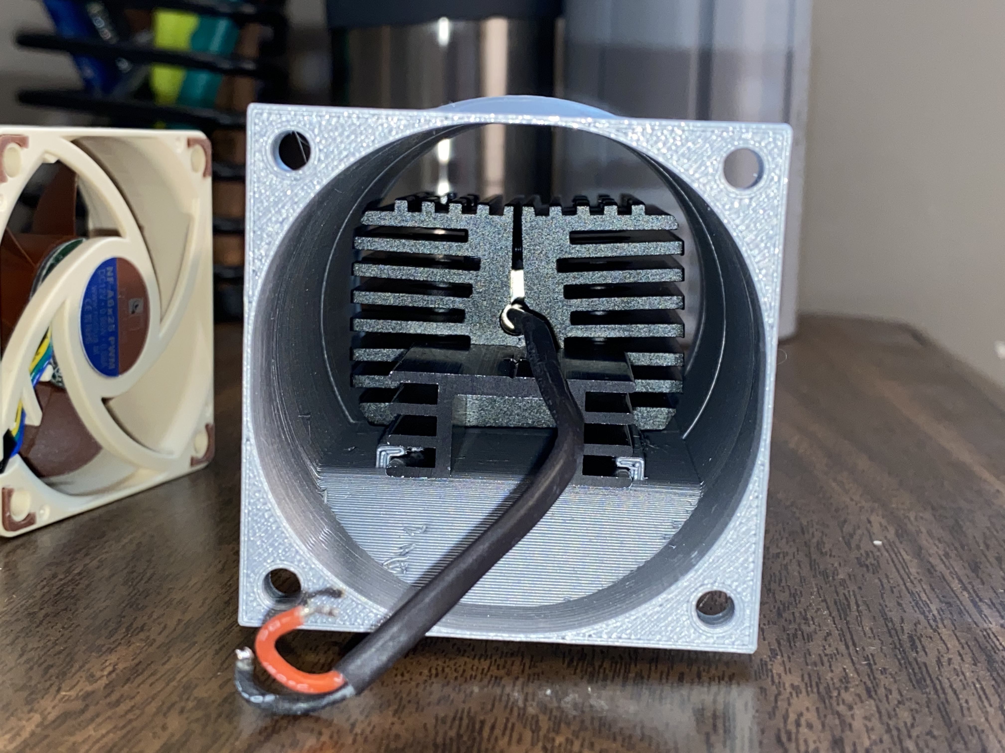
The test rig: 3D printed 65mm Makita-like insert w/60mm fan (no lens on the laser)
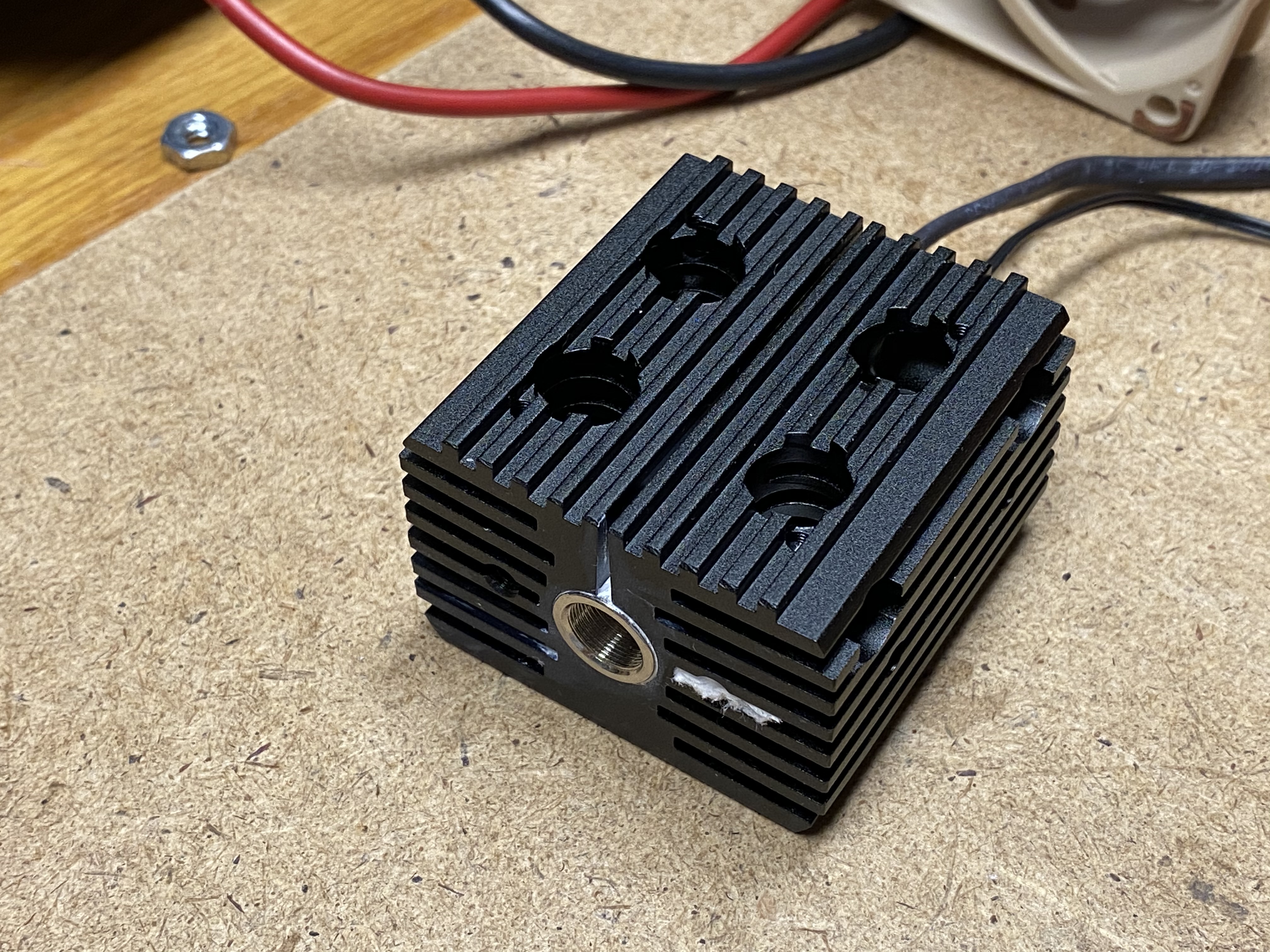
Another view.
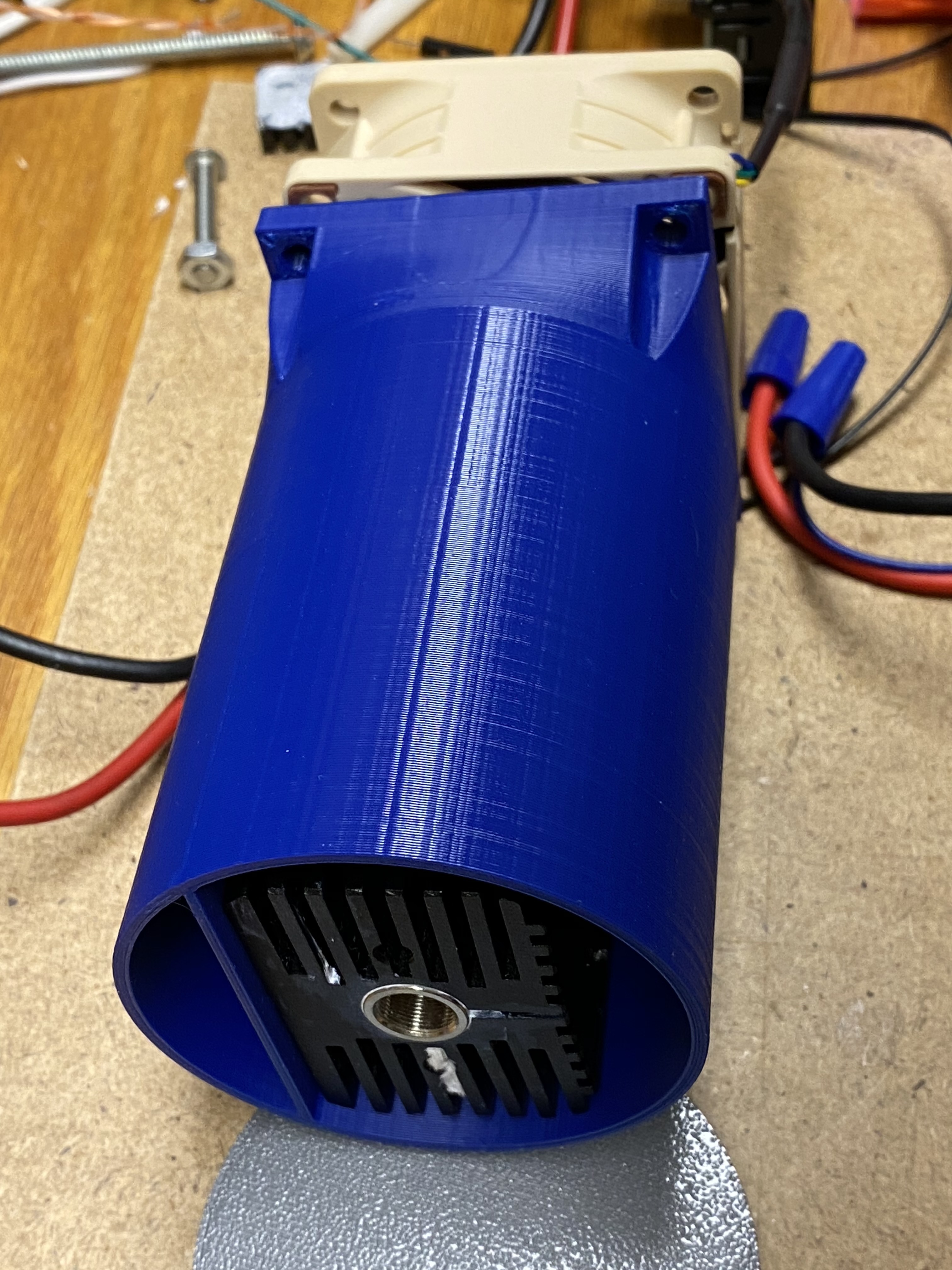
Just the heatsink. Lots of mounting options. Looks like you could screw a 35mm fan on top.
Next steps:
I learned a hard lesson and thermal glued the heatsink to the BlackBuck8M. It is likely inseparable now. Oops. I am looking at a DIY constant current driver to bring the cost down. Also need to do some work on the 3D printed enclosure - I printed it as a proof of concept before I had all the parts.
So far, if you wanted a bare bones 7W laser, you would need these parts (and wire, filament, incidentals, safety googles, etc).
| Item | Low | High | Vendor |
|---|---|---|---|
| NUBM44 w/G2 Lens | $100 | $145 | Low=barnett_unlimited (ebay); High=DTR |
| Black Buck 8M | $39 | $39 | DTR |
| 12V Power Supply | $15 | $15 | your choice |
| Fan | $10 | $15 | Low=your choice; High=Noctua NF-A6 |
| Heatsink | $20 | $20 | Z-Bolt Laser HS-1A |
Low: $184
High: $234
2 Likes
I did some testing with a LM338 voltage regulator, configured to work on constant current mode. It did work as expected, but it got extremely hot at 5A (I did use a heatsink). It’s burning off excess voltage as heat, so that’s not going to work well (12V down to 4.7V => 7.3V @ 5A = 36.5W). I was able to remove the BlackBuck8M from the heatsink (I used thermal glue), so that is good. It wasn’t as bad as I thought it would be to remove. The board has a little flex, and it’s enough to get a corner up and work it off.
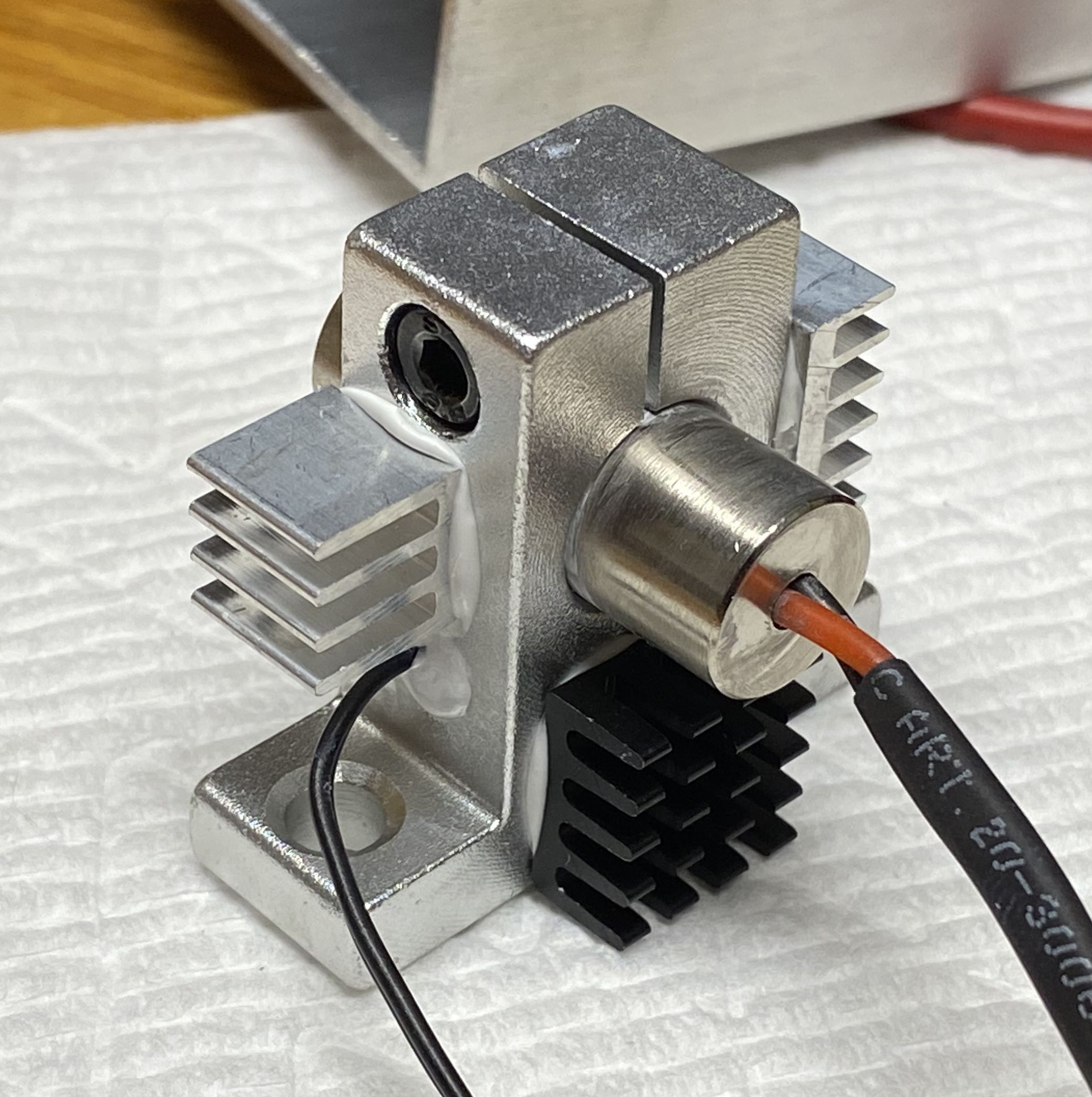
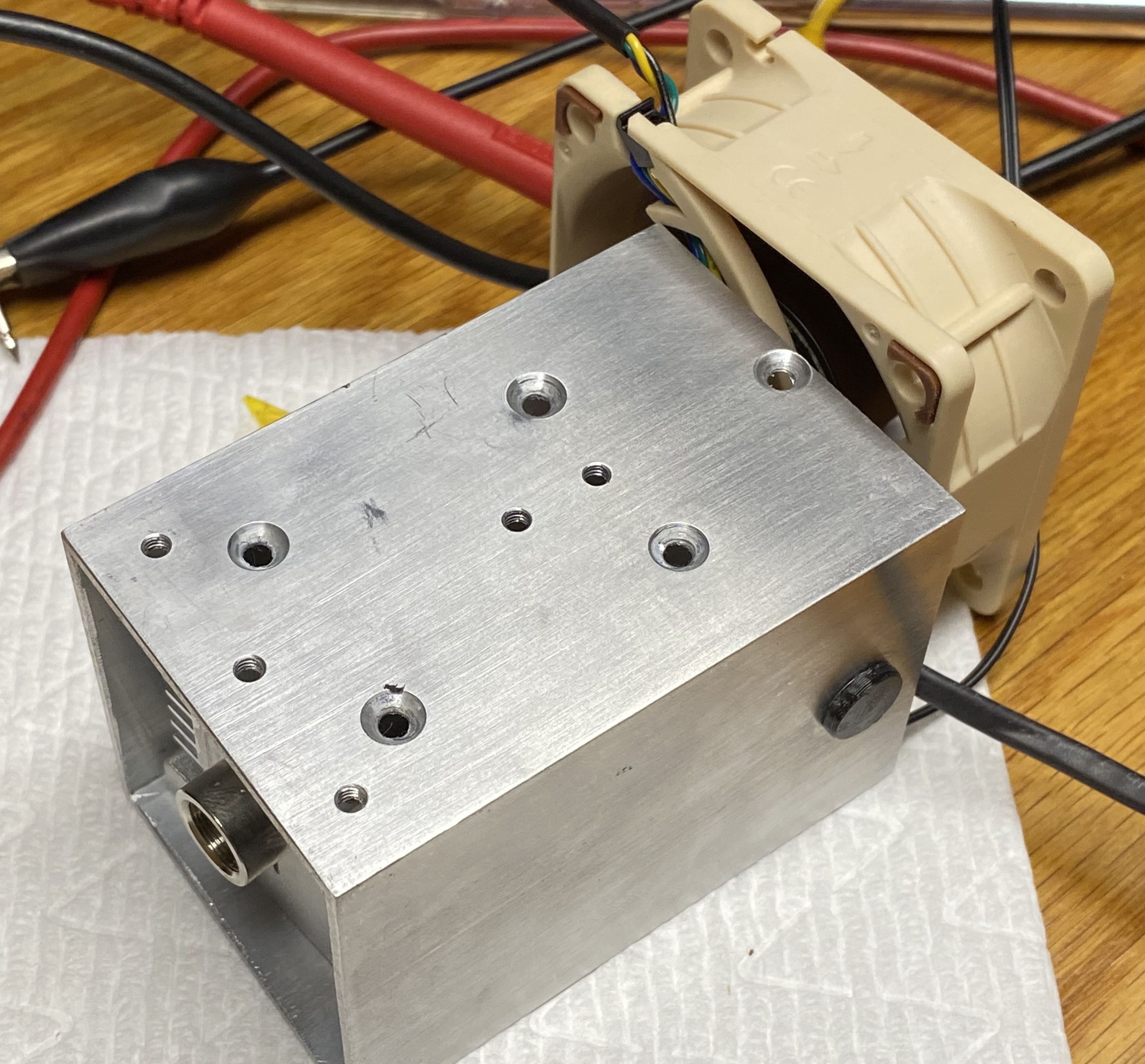
I did some work on the mount:
Added some screw holes to mount the laser heatsink, and a bracket to hold the heatsink for the driver. After further consideration, I think I’m going to move the driver to an external control box. Overall I think it will be easier to build and maintain.
From the laser head, there would be a few wires back to the control box:
- output from driver to laser diode (2 wires)
- 12V for fan (2 wires)
- PWM and feedback for fan (2 wires)
- temp sensor (2 wires)
The first 4 wires are required, and the second 4 are optional. But if you want more data to monitor, you’d need them. I plan to measure output voltage at the control box and compensate for the voltage drop so it reads the diodes approximate voltage.
At this point, I’m going to cobble together the electronics and get some hours on it.
2 Likes