My EspoTek Labrador was delivered early, so I got some tests in with the scope today. I don’t really know what I’m trying to accomplish with this particular test. Just curious how the diode and driver behave.
Disclaimer: I am not an expert on the operation of these drivers or diodes. I’m just observing and hypothesizing for my own knowledge. If I state something incorrectly or if you can provide more insight, please let me know.
Setup:
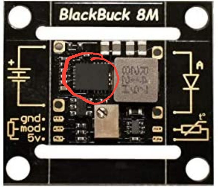
BlackBuck 8M
5A current setting
PWM driven from an arduino
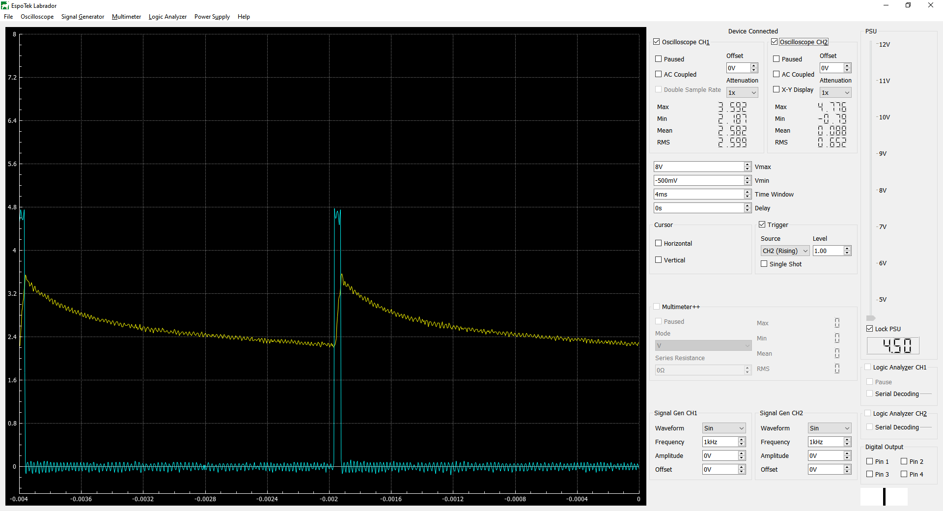
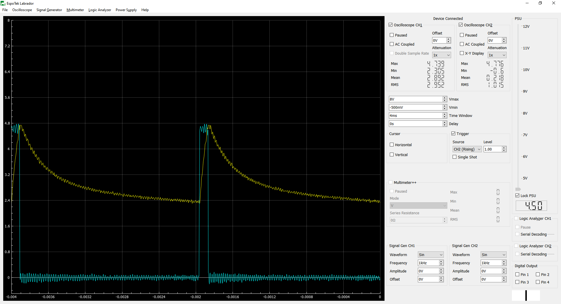
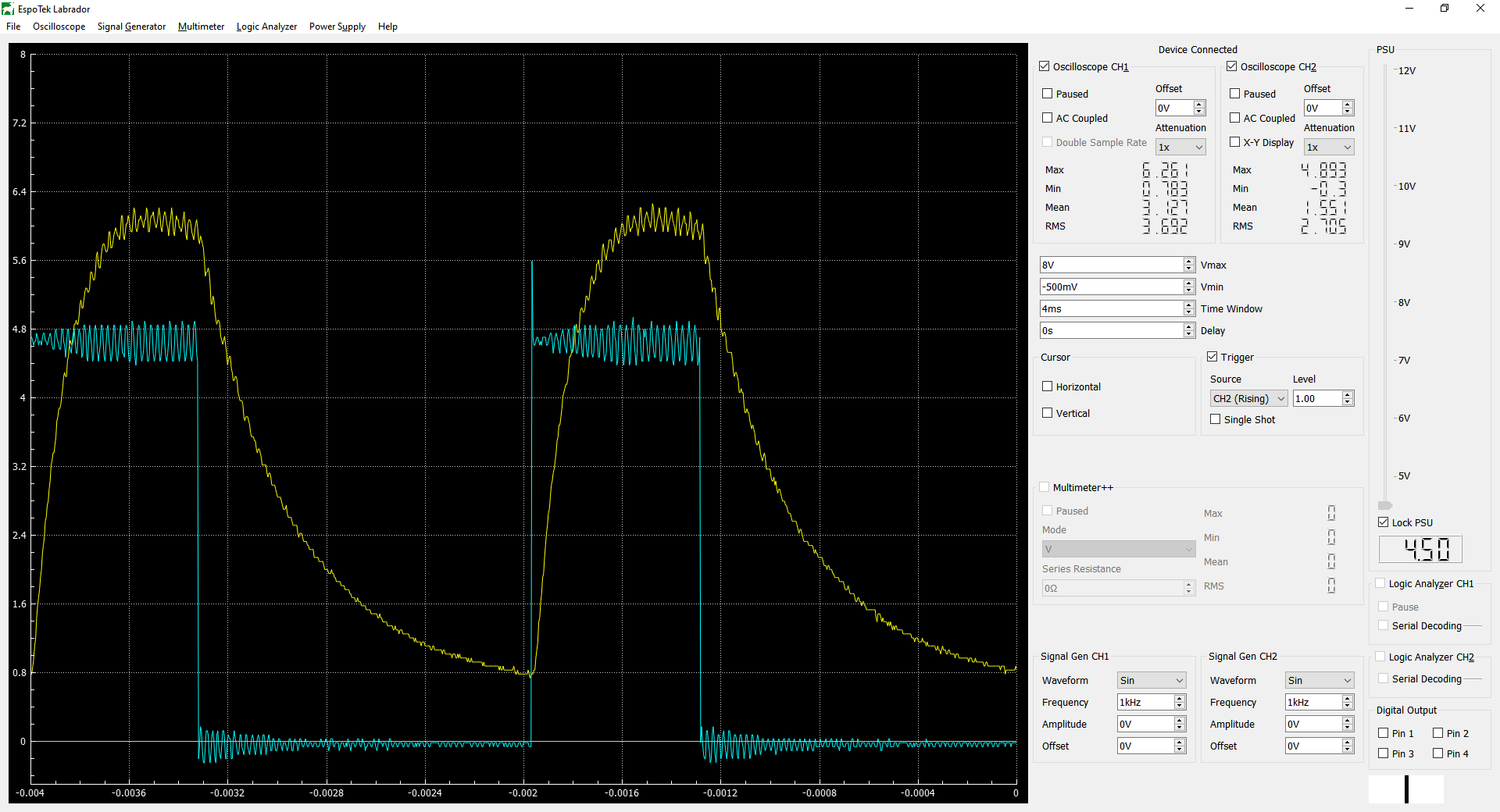
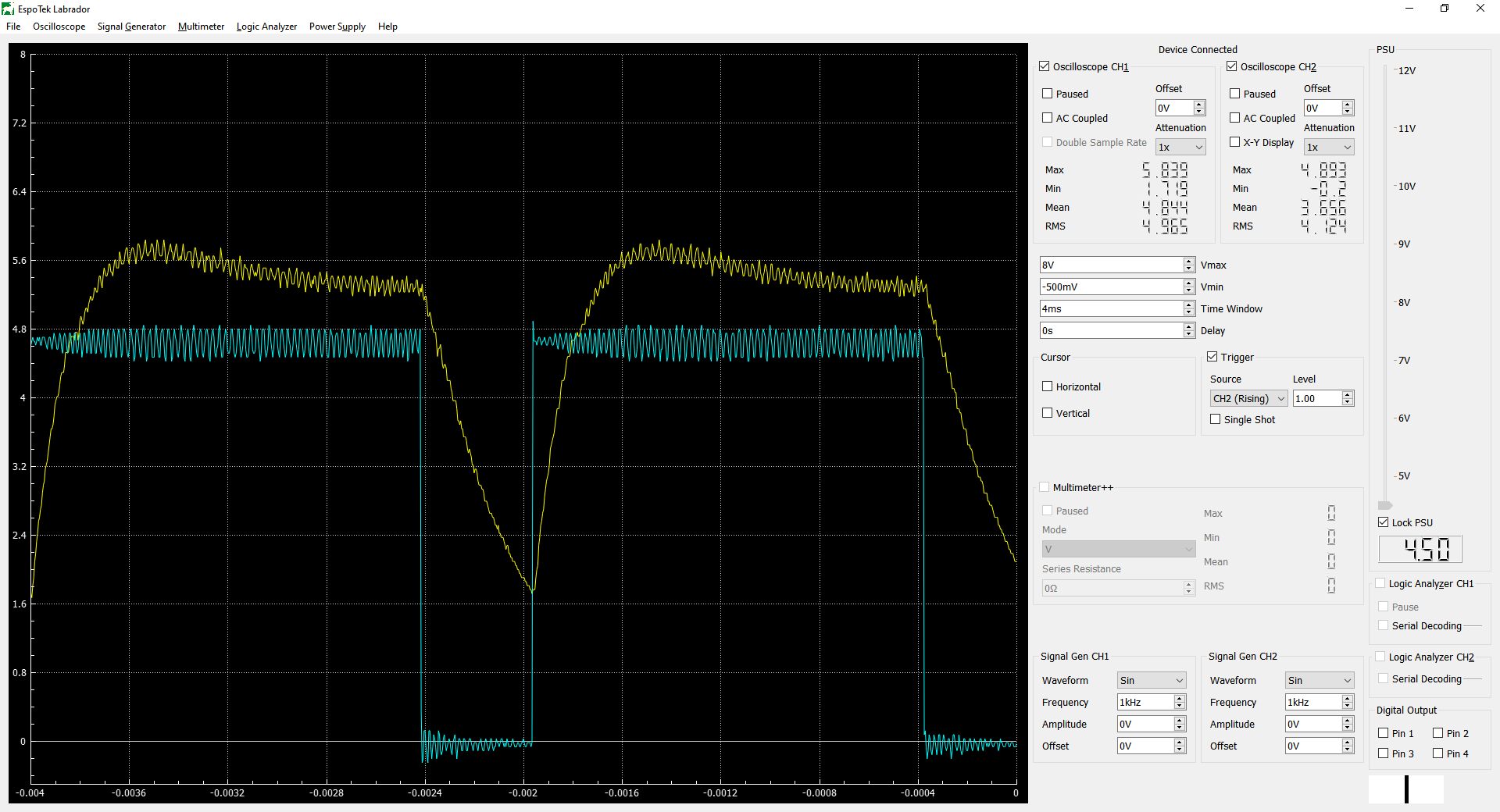
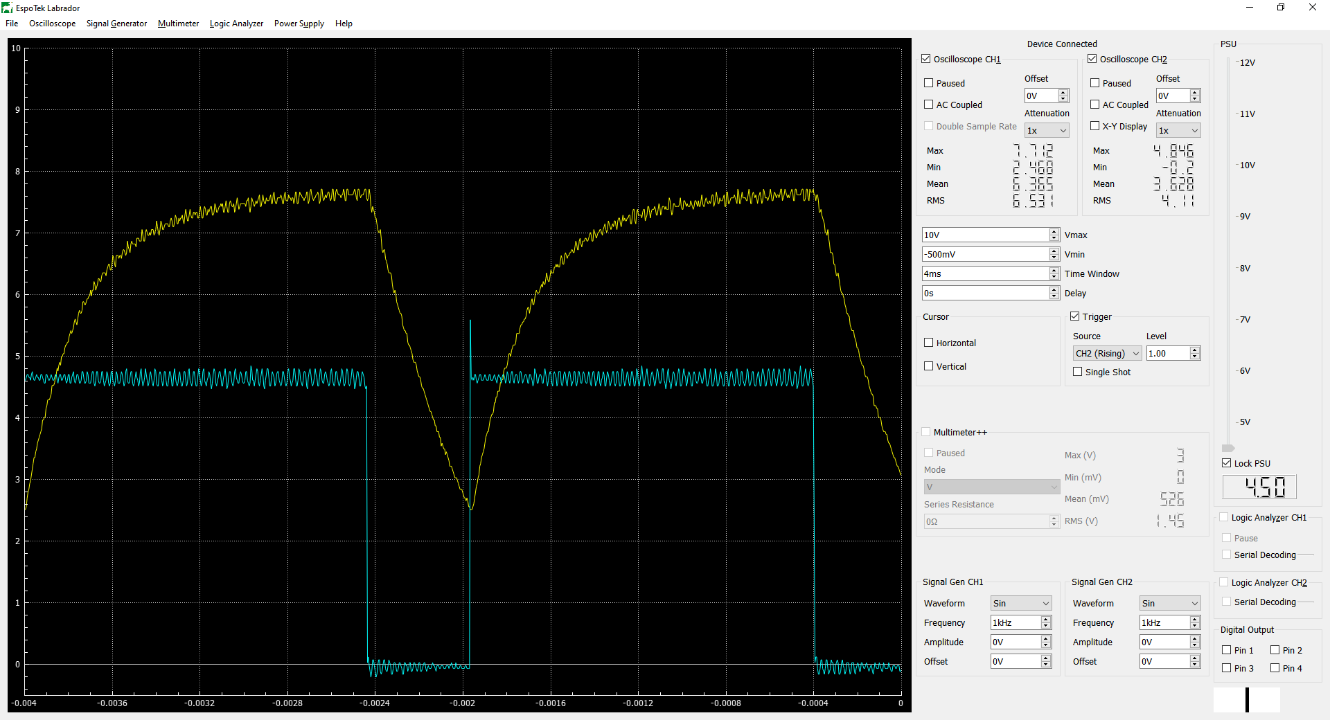
CH1 = Diode Voltage (yellow)
CH2 = PWM Out (cyan)
At low duty cycles, it isn’t strictly an on/off at full power. I hope this will alleviate my issue of still burning the work piece at low power while aiming with the stock driver. That one really had a hard on and off since it was just switching the full voltage on and off.
About 80%: This one is not over shooting as much as the prior test. Peaks at 5.8V and averages out around 5.3V before the cycle starts over. This pattern goes away as you approach 100%.
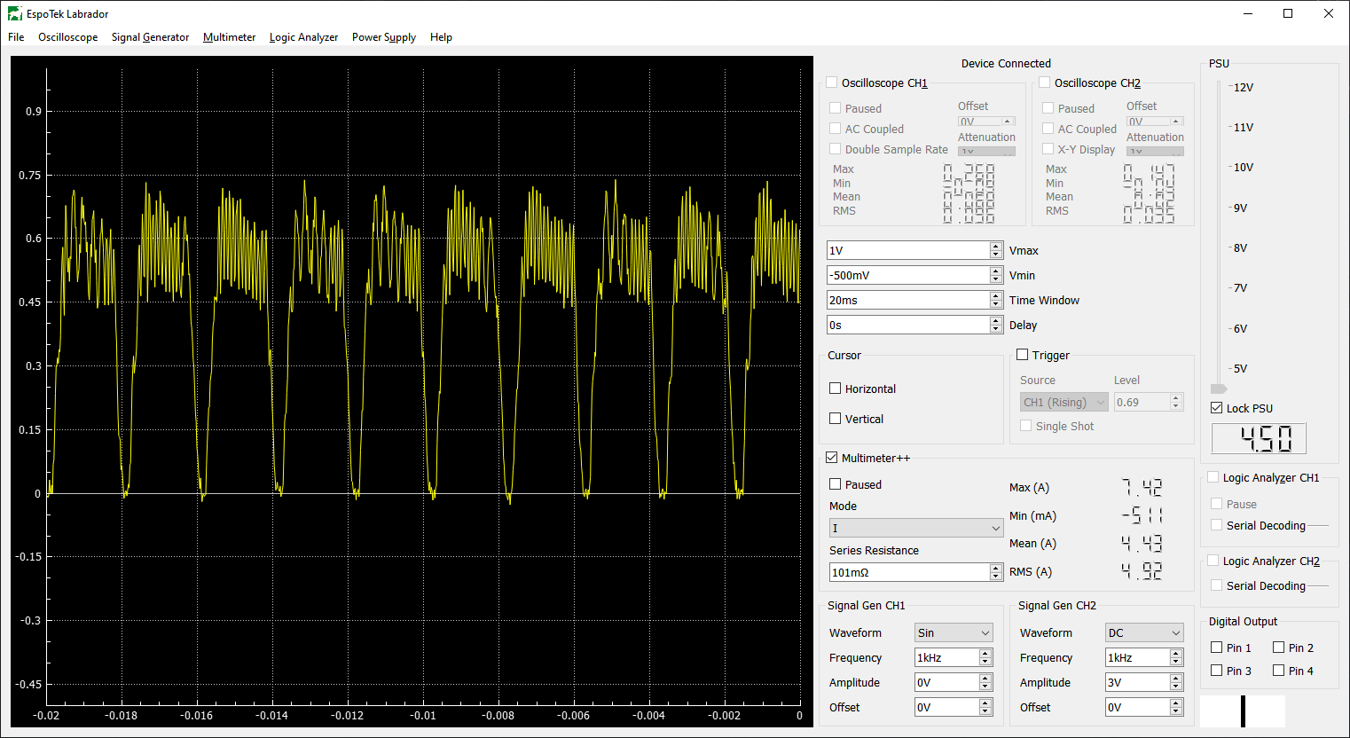
I was curious what the current was doing so I put a 0.1ohm sense resistor in line to see what that looks like. It’s super noisy, but you can kind of see the same pattern. Triggering wasn’t working well due to noise, so I widened the time a little to 20ms across the screen. The scope shows the voltage drop across the sense resistor. V*10 = A
I think this overshoot is a characteristic of the diode, rather than the driver. Using a purely resistive load, there is no overshoot. However, a higher voltage is needed to get to 5A, and closer to the 12V input to the driver, so that might have something to do with it.
I would hypothesize that most constant current power supplies overshoot a little when they first come on. The ones I have looked at use a sense resistor at the output to adjust the voltage being delivered to achieve the desired current. Being relatively analog in nature that will take time to reach equilibrium.
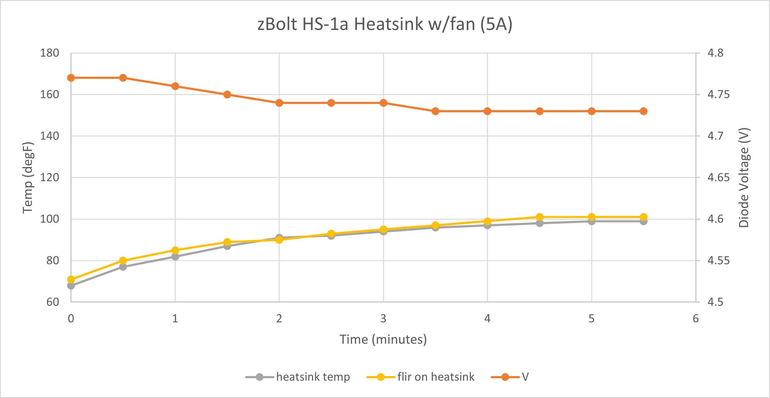
Electrically, the test setup was identical to the previous ones. Voltage and temperature over time are much more like stock. I would have no concerns running this for long periods of time.
Next steps:
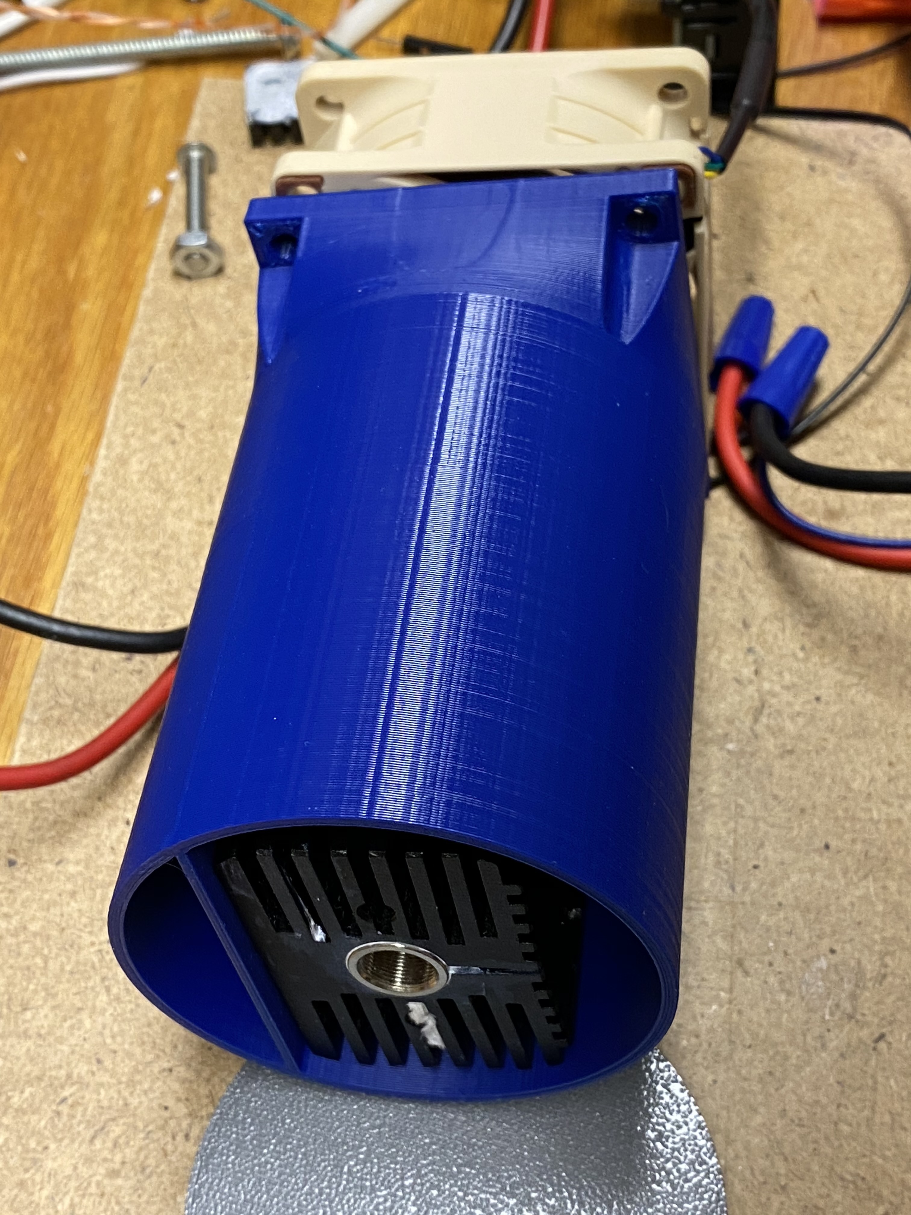
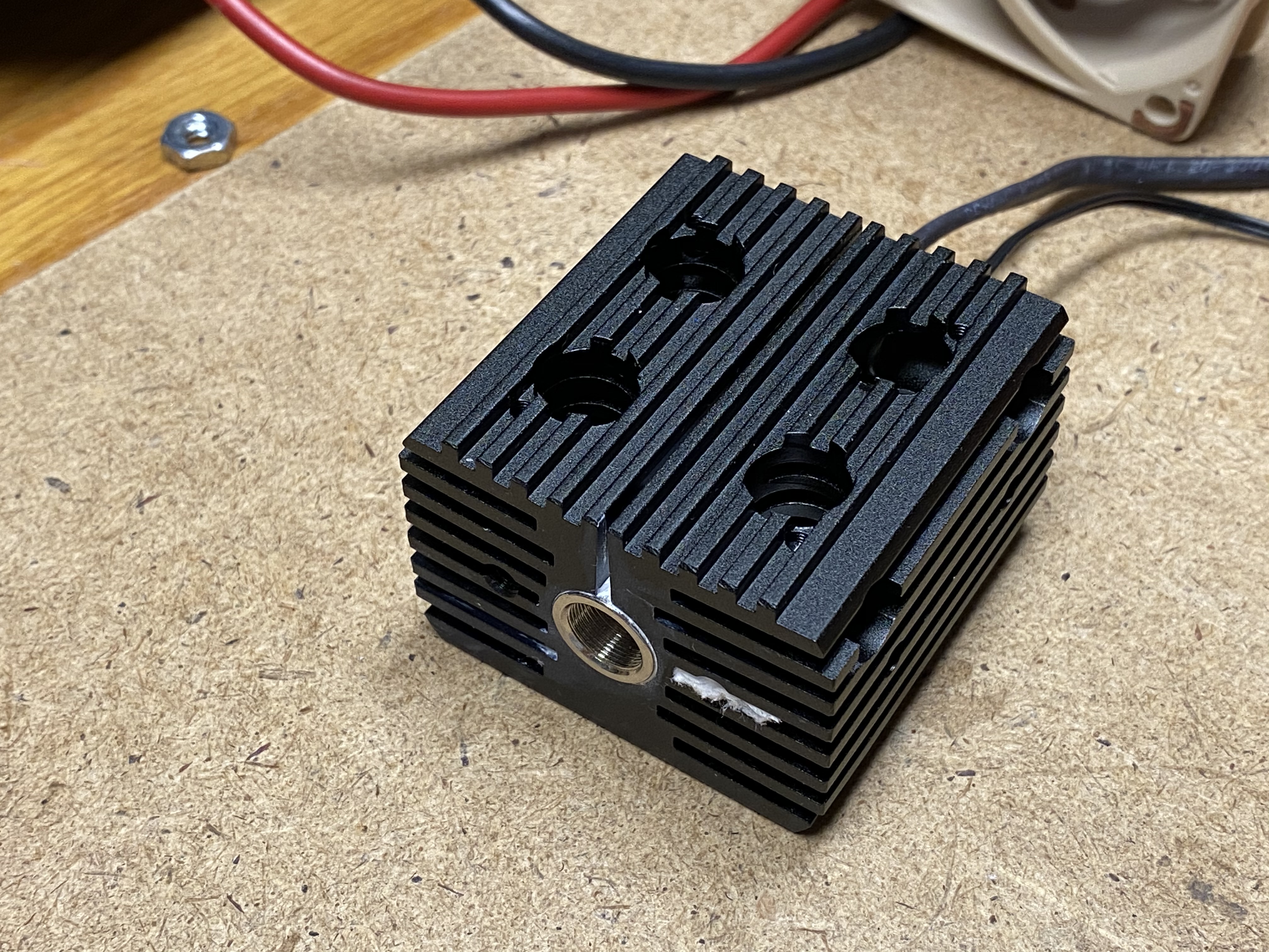
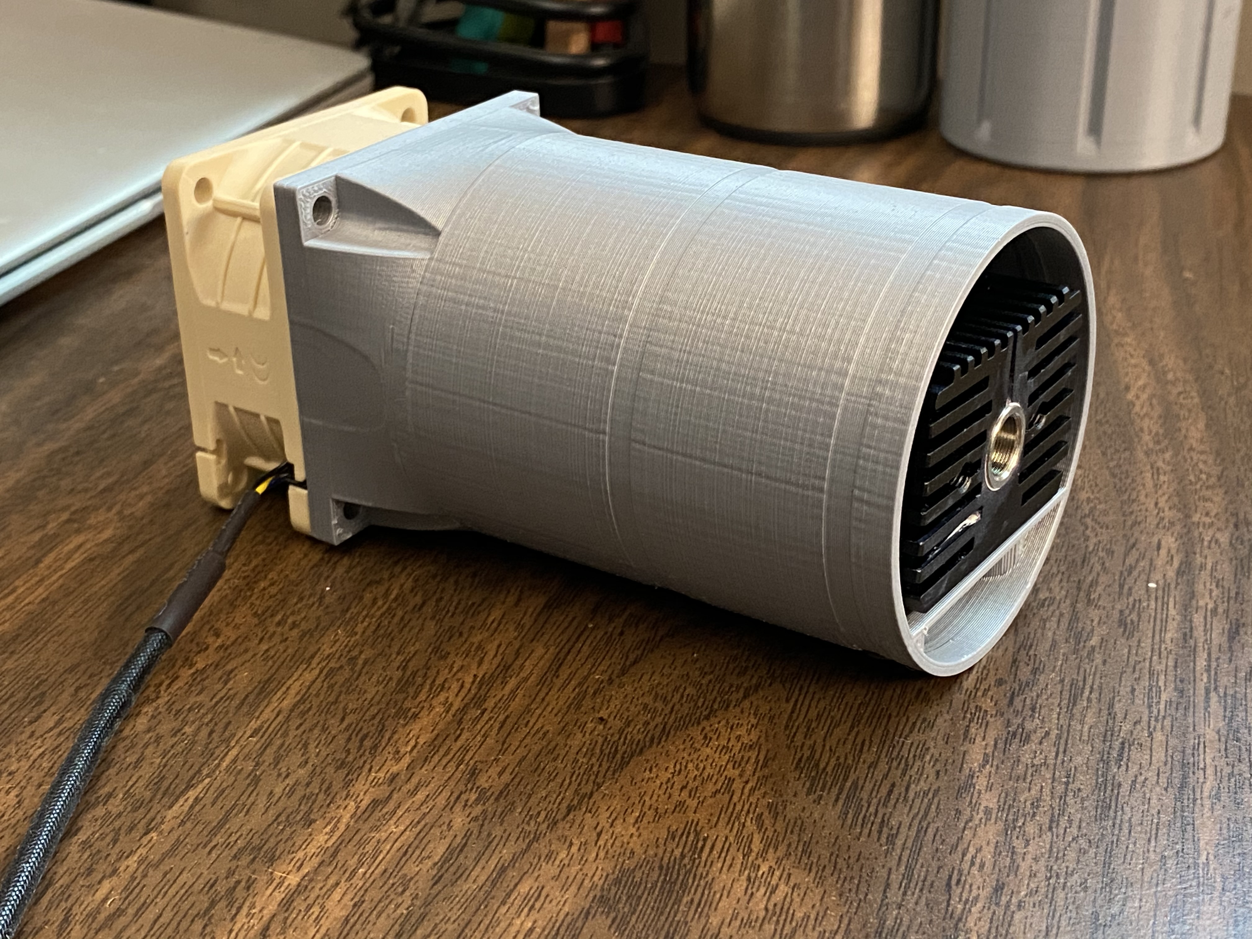
I learned a hard lesson and thermal glued the heatsink to the BlackBuck8M. It is likely inseparable now. Oops. I am looking at a DIY constant current driver to bring the cost down. Also need to do some work on the 3D printed enclosure - I printed it as a proof of concept before I had all the parts.
So far, if you wanted a bare bones 7W laser, you would need these parts (and wire, filament, incidentals, safety googles, etc).
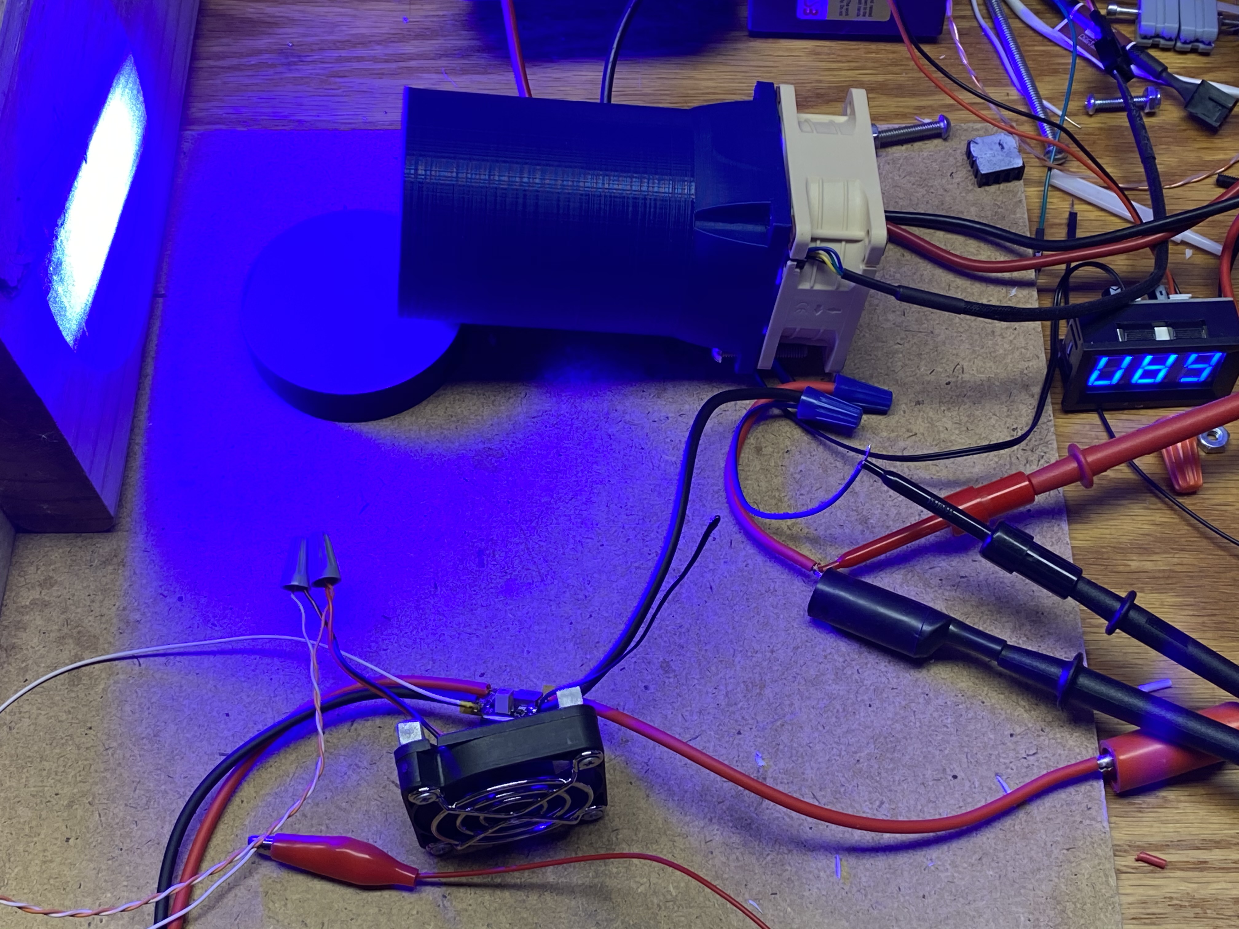
I did some testing with a LM338 voltage regulator, configured to work on constant current mode. It did work as expected, but it got extremely hot at 5A (I did use a heatsink). It’s burning off excess voltage as heat, so that’s not going to work well (12V down to 4.7V => 7.3V @ 5A = 36.5W). I was able to remove the BlackBuck8M from the heatsink (I used thermal glue), so that is good. It wasn’t as bad as I thought it would be to remove. The board has a little flex, and it’s enough to get a corner up and work it off.
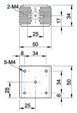
Added some screw holes to mount the laser heatsink, and a bracket to hold the heatsink for the driver. After further consideration, I think I’m going to move the driver to an external control box. Overall I think it will be easier to build and maintain.
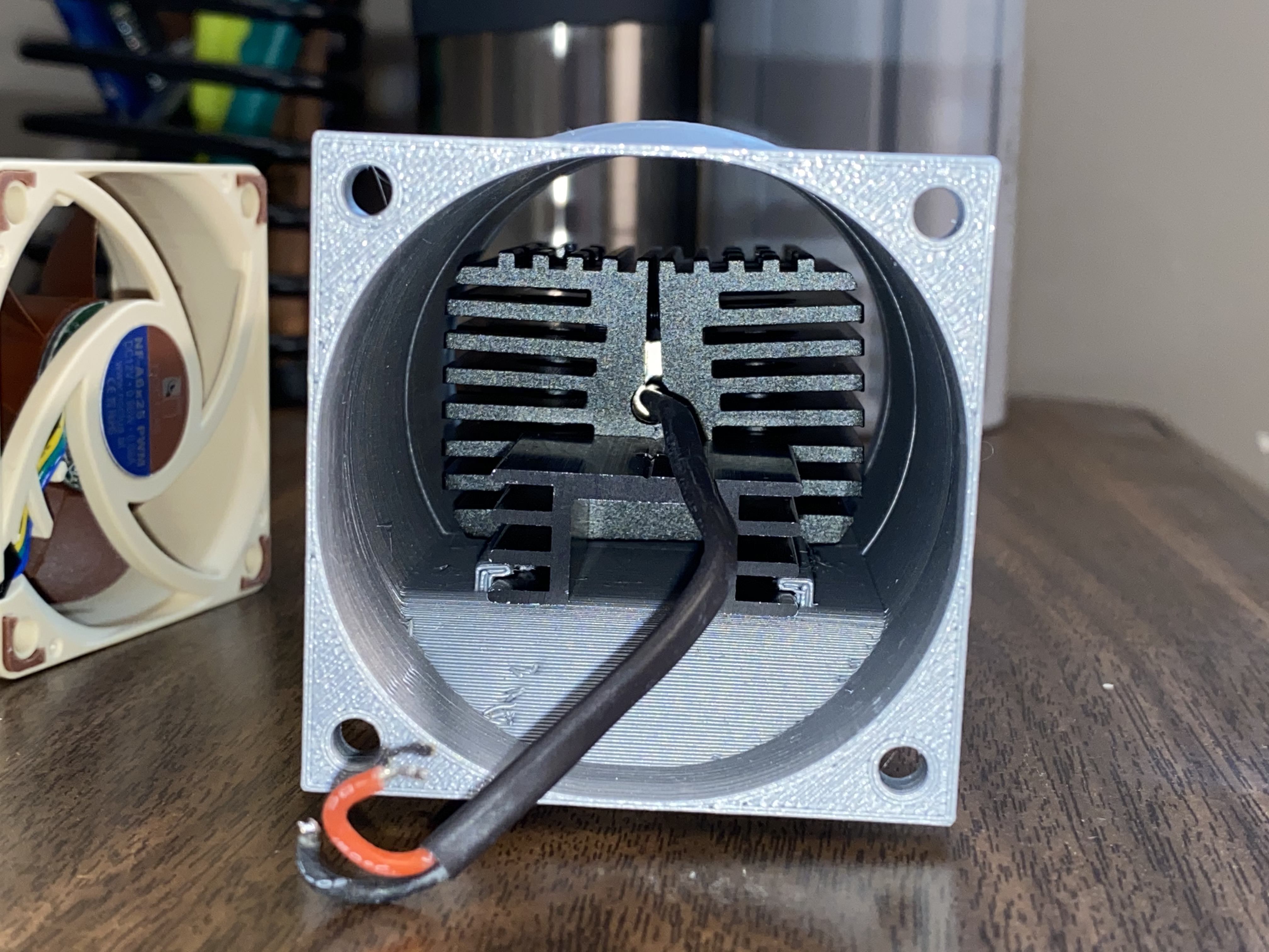
From the laser head, there would be a few wires back to the control box:
output from driver to laser diode (2 wires)
12V for fan (2 wires)
PWM and feedback for fan (2 wires)
temp sensor (2 wires)
The first 4 wires are required, and the second 4 are optional. But if you want more data to monitor, you’d need them. I plan to measure output voltage at the control box and compensate for the voltage drop so it reads the diodes approximate voltage.
At this point, I’m going to cobble together the electronics and get some hours on it.
Not worth it in my opinion. You might be able to get the cost down, at the trade off of added parts (Buck,LM338,current shunt) and more to assemble. The BlackBuck8M is ready to use out of the box once you solder on wires and put it on a heatsink.
As an aside, the power supply that came with my laser does have voltage and current adjustment. But the current adjustment wasn’t nearly stable enough to use with the laser. When it got close to the limit, it would drop out. And it really didn’t like PWM. It’s kind of like this one: ebay.com
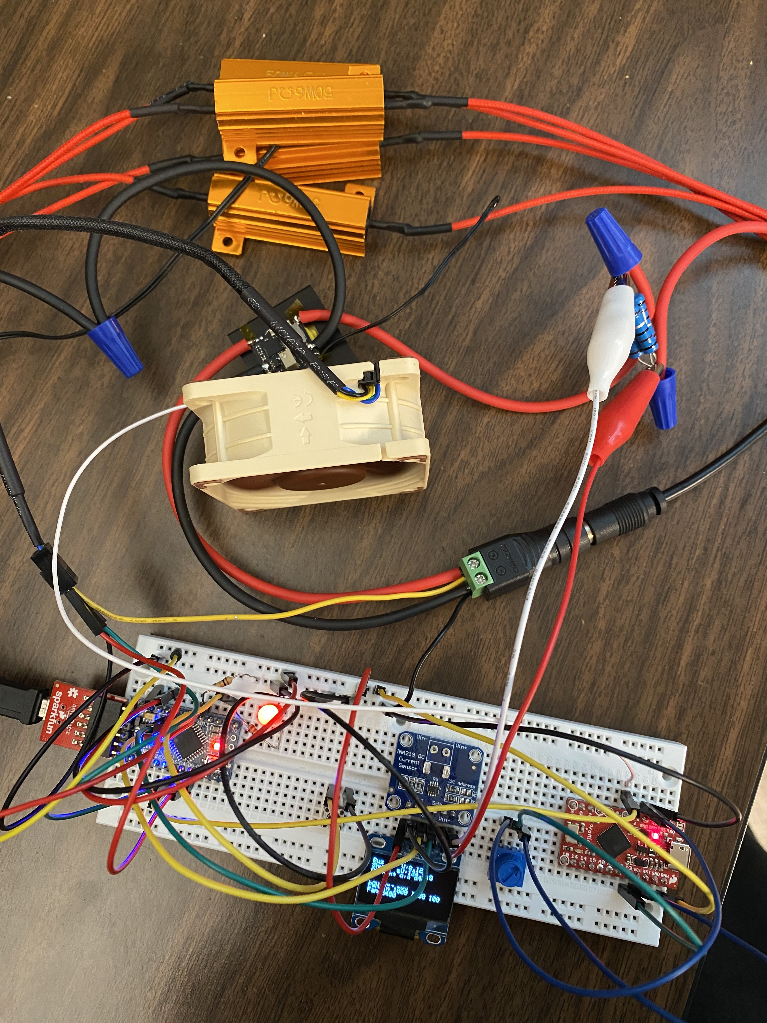
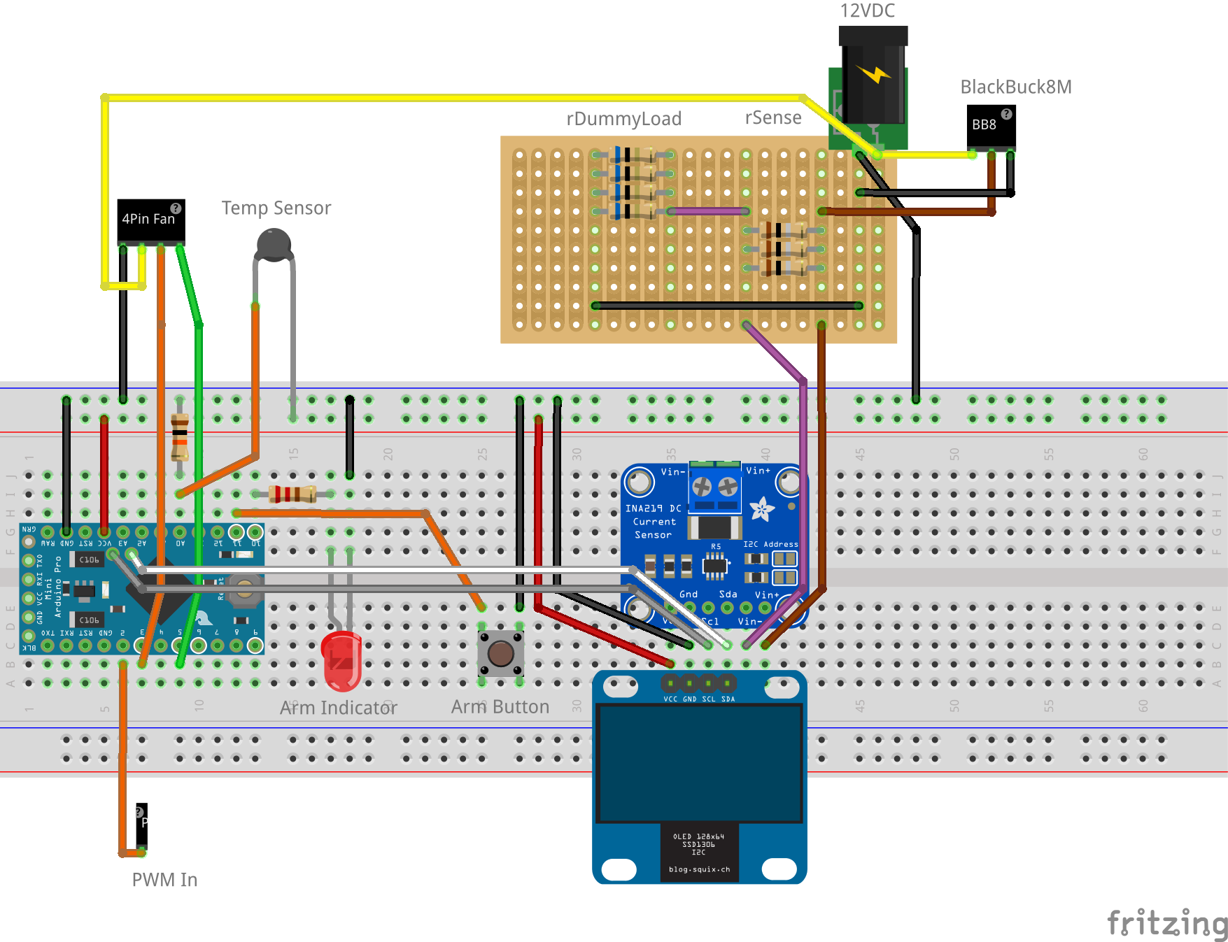
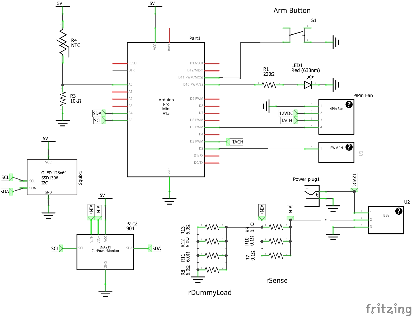
Not quite ready for the garage, but it’s progress. I at least have the electronics hashed out and code working. This is basically all monitoring and some safeties. The PWM from GRBL will feed the BlackBuck8M directly. There will be a master relay that the Arduino will enable when armed.
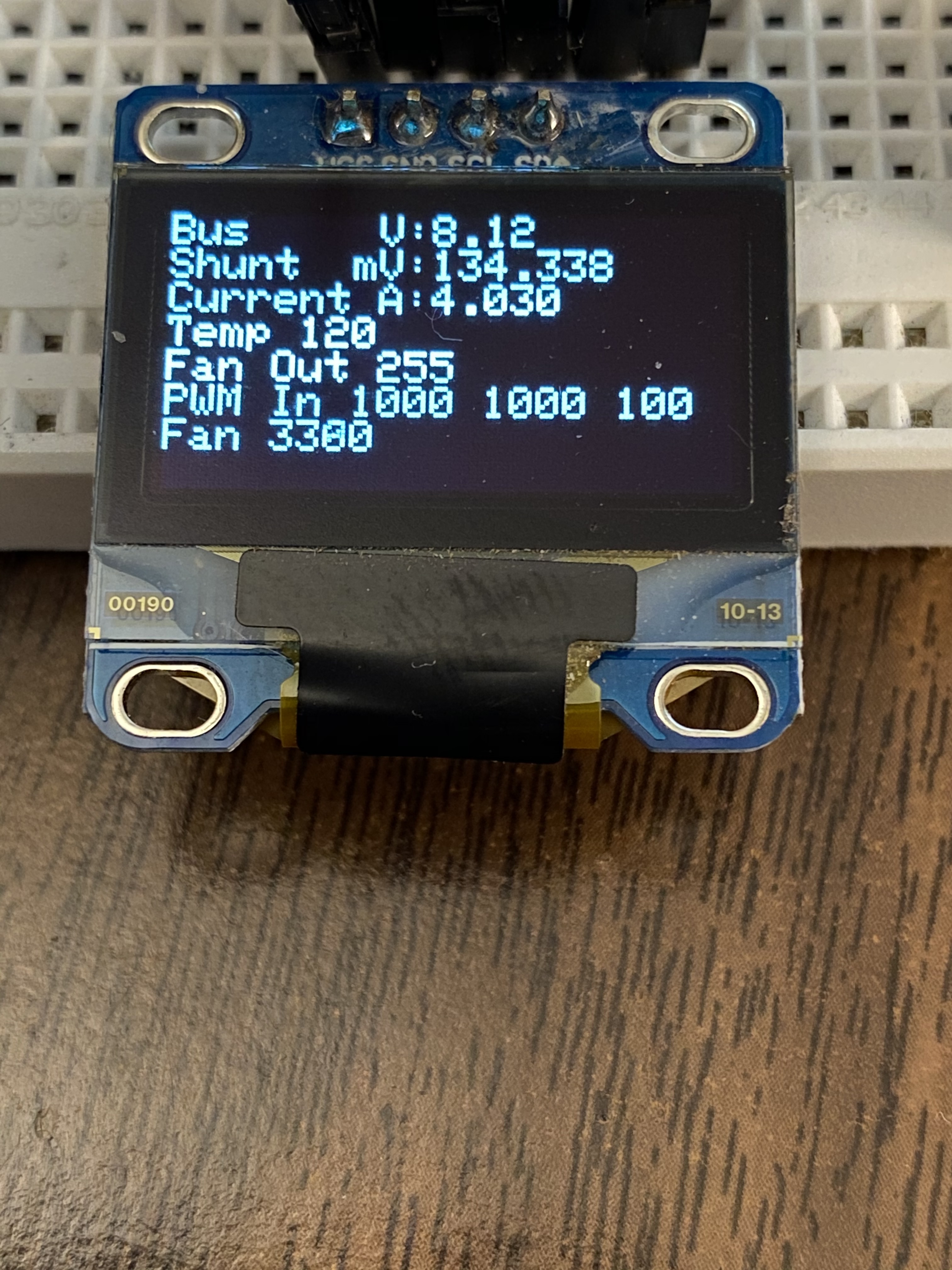
Shunt: voltage across rSense (for calculating current)
Current: current delivered to the load
Temp: Temperature of load (10K thermistor)
Fan Out: PWM Out (0-255=0-100%). Varies with temperature (not needed, just for fun)
PWM In: [PWM Width] [PWM Frequency] [PWM Percent] (not a good example in the pic)
Fan: RPM
All data is also spit out on the serial port for logging.
Safety sequence (not fully implemented yet):
If button pressed, arm laser (will energize a future relay feeding the BlackBuck8M)
If PWM from GRBL not seen for 5 seconds, disarm laser (time may need to be adjusted)
If current goes to zero for x seconds when there should be current, disarm laser
If fan speed drops below threshold for x seconds, disarm laser
If temperature goes above threshold for x seconds, disarm laser
My intent with the arm button and safeties is to make it as fool proof as possible. When you are ready to laze, you must arm it (that’s also my queue for safety glasses). If anything goes wrong, it will automatically disarm. This way power outages, forgetfulness, and equipment failure are all covered.
It might also be nice to have an output back to GRBL for feed hold. That way if a safety trips, it would pause the job.
What size 12V supply are you using (how much current capacity)? How much current does this whole affair require at full power? I’m in the process of designing the electronics for my router and I’d like to make sure I have enough capacity for a laser like this someday.
Question, (because i don’t use grbl) if the program encounters an error and holds(say a pause or hang) does it continue to send a pwm signal? I ask because in Marlin if a laser power is set and then it hangs on a pice of code I think it continues to output a pwm signal. because that is a major safety point you didn’t mention explicitly.
This is maxed out on my 1.5 ohm load:
Load: 9.8V at 4.8A, 47W (watts calculated)
Wall: 120V, 0.75A, 46W (watts on kill-a-watt)
Power Supply: 12V, 5A, 60W (rated)
I know I can’t defy the laws of physics so there must be a measurement error, but I’d say it is overall it looks very efficient. There is a 2.2V drop across the blackbuck 8M, and that is the limiting factor in this test. Once the laser is hooked up it can draw more than 5A at 4.7ish volts, but 5A will be my target. A 12V/5A power supply hasn’t let me down in all my testing, including when the laser is hooked up. (none of this includes any of the MPCNC electronics, motors, etc.)
I’m not familiar with the laser mode on Marlin. But generally, I don’t know how this type of failure could be easily detected. If the MPCNC controller says the laser should be firing, it’ll do that (once armed). You’d have to take in a stepper motor pulse or something - so if no movements are being made, and the laser is still on, you could disable it.
Maybe yourself or others can speak to the likelihood of this type of failure?
Marlin and grbl really are a lot of parts. If you have an error in your gcode or gcode sender, I would imagine marlin or grbl in laser mode would shut off the pwm. If you have a code error and the progression of the loop or motion stopped, I don’t think there is a good way to stop that, except just working on those bugs to avoid them.
There’s no way the laser should be left alone, so those (hopefully rare) kind of mistakes would ruin the work but ideally the cost would stop there.
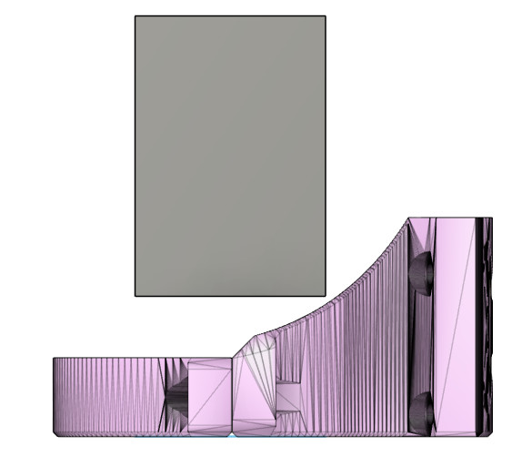
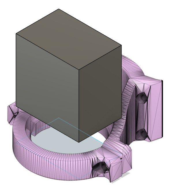
I think it would work. The top part of the DW660 mount is about 63mm ID, which shouldn’t be an issue, aside from the odd profile. The heatsink won’t fit through bottom part, so it would sit a little high. The inner diameter of the lower mount is around 45mm. (heatsink shown to scale) I would envision a collar that goes into the lower mount, but you can see the relative sizes below.
Edit: I just realized I put the DW660 mount upside down. But it should still work, I think.
It’s about 25mm from the bottom of the heatsink (where the lens would be) to the bottom of the DW660 mount. Focusing would be a pain, but I use the Z axis for that anyway. You would likely not be able to use a G2 lens with a focal length around 30mm (The G2 lens is also the most efficient). Other lenses should be fine. Mine is set around 60mm.
If there is interest let me know, and I can take a stab at it.
In other news, I did run it for 45 minutes in the garage with no issues (although it was 30degF). The display and monitoring is nice to have, but I’d probably forgo it at this point. I would still keep the arduino for a safety (arm, stay armed with PWM input). The adjustable fan speed at the laser is pointless - it should just run all the time to help with smoke anyway. I ran the BlackBuck8M with a heatsink but no fan and it was fine (in the cold garage). But at room temperature, it would need it’s own fan for cooling.
I’m definitely interested and I will probably ask for some help in a few months when I get rolling on that project. I am just getting ready to order my spindle and it dawned on me that it might not work with your type of setup. Thanks for the help!
did you do a lot of research on laser (aka constant currant) drivers? just curious what others you looked at besides the M8 and why you decided to go with that one in particular. i know size was important to you (because you wanted to keep the driver with the laser head), but was there any other reasoning?
can’t find any M8s in stock so just looking for possible alternatives.
I didn’t do a ton of research. That one came up and seemed to be good. As long as it is a constant current driver, with good adjustability, and proper current ratings - it should work fine. Having one with a decent heatsink built in would be nice. Also, the small size works against you sometimes, as it was a little tough to solder.
OptLaser has some good options, but they will cost a little more.