A crown

I havent seen anyone do this design before:

I did this with Estlcam, but I had to write my own preprocessor to get it to work, so this is not really representative of what Estlcam can do.

It might be possible if you use the v-bit to clear the pocket and you don’t mind waiting for hours and hours. To use an endmill like I did for clearing the pockets requires a ton of external work to preprocess the artwork. Would not recommend.

As for the defects in the work, I think there are a few things that can make this better. One, the grain direction is a huge factor. The v-bit left “fuzzies” behind when cutting parallel to the grain. Maybe a finishing pass would help with that. The part is also weak depending on the grain orientation and thin parts break easily. On the parts where I’ve done endgrain, it is much better both in surface finish and strength for thin parts. For cutting boards, it’s win-win.

Another factor is Estlcam doesn’t respect the climb milling direction for carves. I think the bit wandered into the workpiece a bit. Again, a finishing pass would probably help.

A couple years ago when I was playing with pine and MDF for testing I was using F-engrave. I just might have to go back to that.

14 Likes

Could it be easier to copy and shrink the vectors in inkscape and make two cutting operations? One with flat endmill for open spaces and one with the v bit?

Estlcam does allow you to use an endmills for clearing carves. Why did you need to make a post processor to do this?

I had decent luck by simply doing an inside and outside carve but then setting my finishing pass to +/- 1mm depending on which carve side I was doing in order to oversize and undersize the parts. It wasn’t perfect but pretty quick to do.

3 Likes

Aha, you’re right! I was unable to get this to work before, but by entering a large maximum width and an endmill tool, I got it.

Unlike the ‘hole’ tool, I did not see an option for ‘island’ but it looks like it automatically avoids other curves, not just the one you’ve picked. So it is in fact possible after all. Thanks!

Those little narrow areas where the endmill can’t reach need to be pocketed out by the v-bit. That was the reason I had to go to all the lengths to separately compute the endmill-reachable area and exclude it, so I had a zone of v-bit pocketed areas.

1 Like

No problem! Sounds like you enjoyed doing it the complicated way so at least you had fun!

Walnut and pine this time. Used Rob’s advice and it is much easier.

I noticed there is possibly an issue with the v-bit not being a perfect point but having instead some nonzero (effective) diameter. This makes the pocket slightly wider and the plug slightly narrower and the plug bottoms out before the sides get snug. I used sandpaper to grind down the plug until it fit snugly, and it seems to have worked.

In the future I might try to make the plug short by a bit so it fits straight away without sanding. If there are large areas, I wouldn’t want them unsupported if the plug is too short. I was thinking I could use a small bit of clay during a dry fit, and the clay will squash down to the gap size. If it is small then that’s fine, or I will know the size of spacers I would need.

Here’s some more pictures

11 Likes

That is a very very very good fit!

2 Likes

Most likely you can fiddle with the settings to dial that in. That nonzero diameter is probably the size of the gap, or maybe it’s double the size of that gap…

If you make the plug a little shallower, you can fill the gap with epoxy. It doesn’t shrink when curing, and will be more than strong enough to support the inlay.

2 Likes

You can try to put a little glue into the gaps, wait for it to get tacky and then sand the piece. Your dust from sanding will stick to the glue and make it look like there was never a gap to begin with :wink:

1 Like

This there is genius. The finishing pass with negative numbers. If this works I don’t have to combine F-Engrave and Estlcam for more intricate inlays. Thanks so much…

It does, just draw it out in cad to figure out how much of an offset you need based on how much clearance you want under your plug and the angle of your cutter.

I have a 30 degree but and did 1mm over cut and 1mm undercut.


I think my issue was the fixturing and my speeds creating some issues. Oh yeah, and I forgot to mirror the plug :slight_smile:

2 Likes

Sweet, I have got a 30°, too. Will just use those values than. Which depth did you have?

For the record, I don’t think the offsets are strictly necessary to make the plug smaller than the pocket. I was cutting the pocket with no offset and a depth of 3mm, and for the plug I cut with an initial depth of 3, and a cut depth of 1, with no offset. This made the plug a total of 4mm tall, and the drawing plane was near the bottom of the plug. The top surface of the plug is ‘naturally’ smaller according to the taper of the bit, but it’s the proper size when inverted.

I think the offset can still be useful to accommodate the imperfections in the cutting bit, but I don’t think it’s required (or desirable) for projecting what the shrunken top surface of the plug should look like. For very fine details, the plug might not touch the top surface at all, so a negative radial offset would make it disappear, but cutting the original artwork with a starting depth will produce a short peak. I feel like there are other areas where it might not be equivalent (radial offset vs. depth offset) but I get too confused trying to work it out in my head.

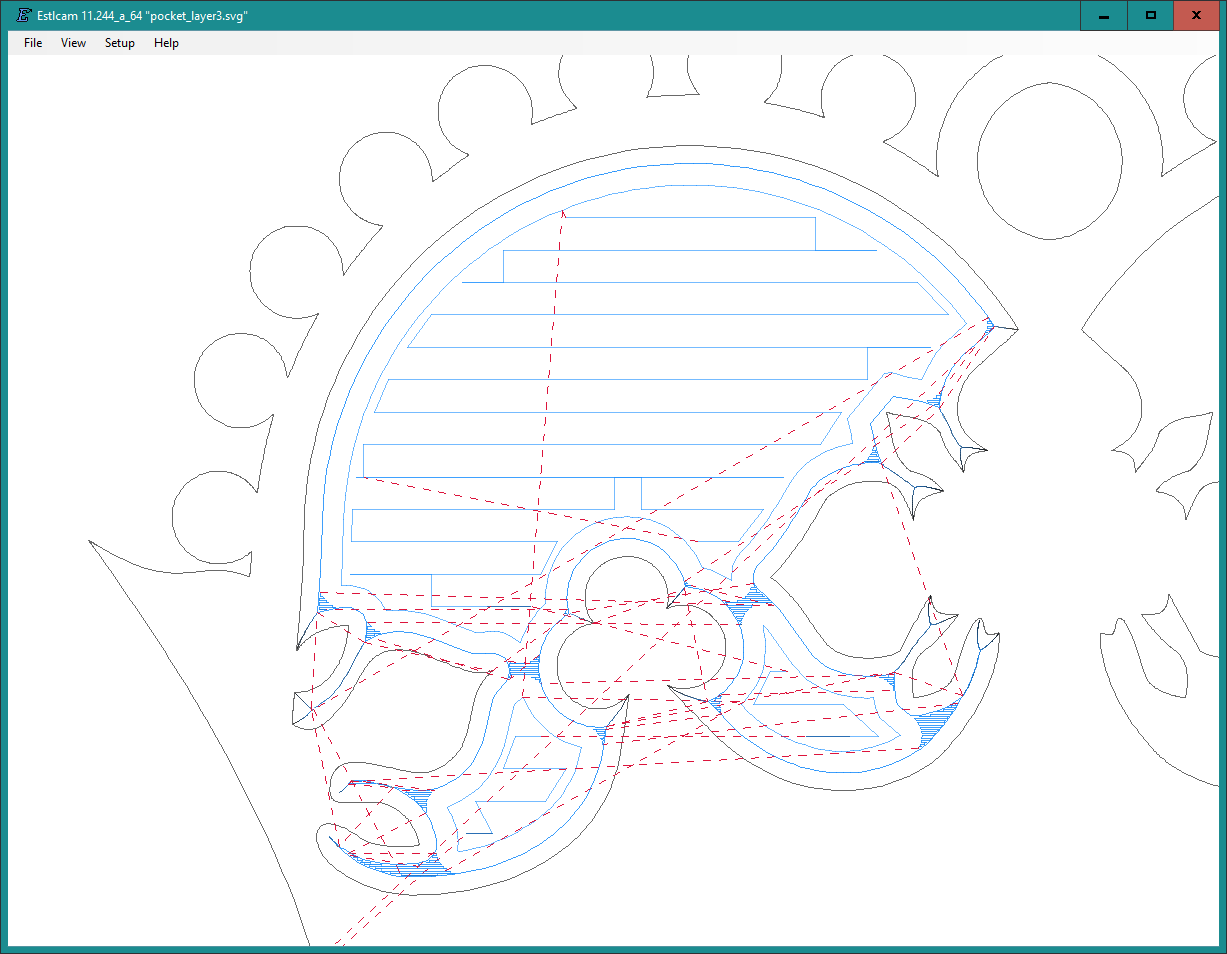
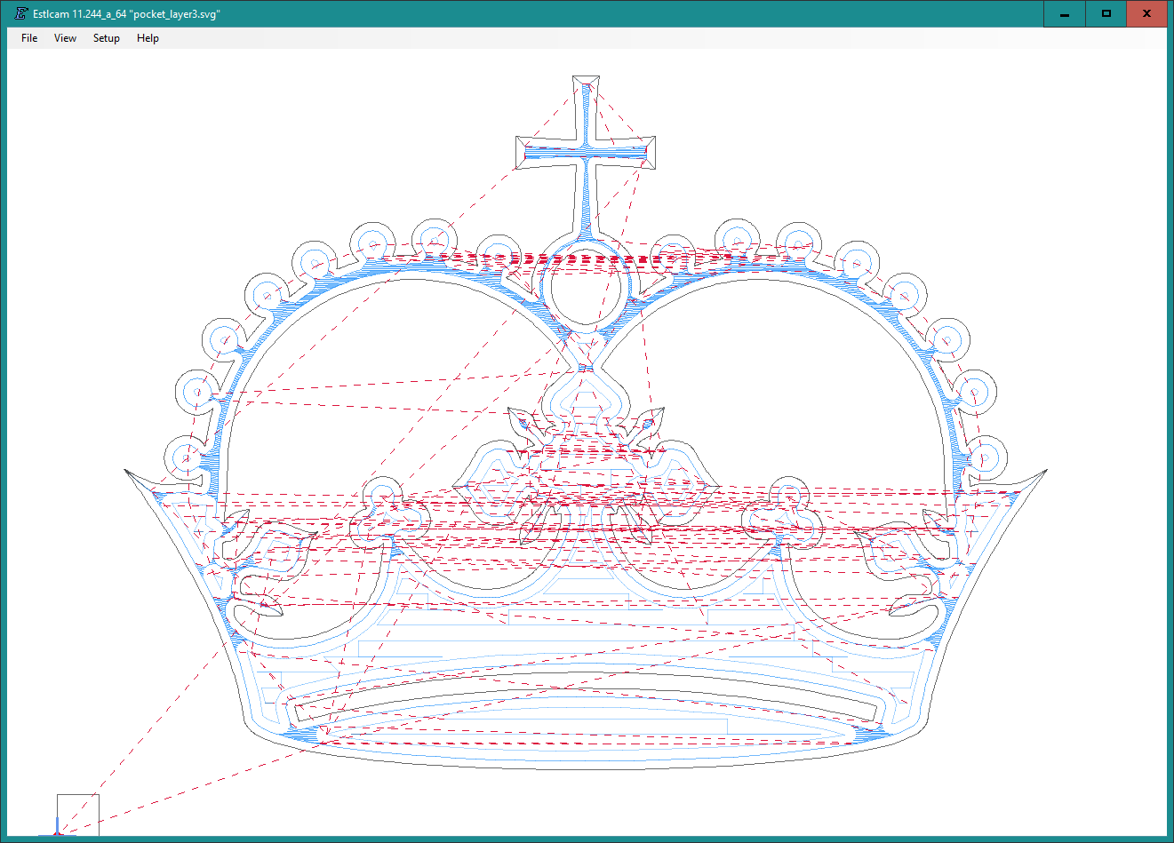
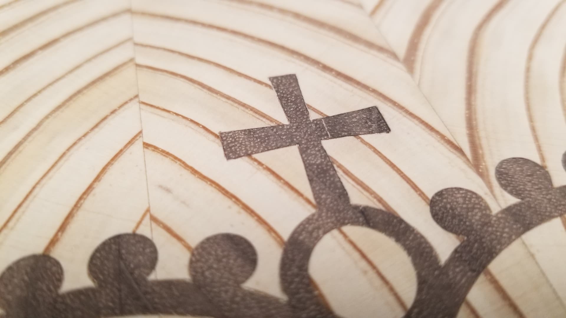
For the second crown I used a positive offset to leave 0.4 mm of stock, and I cut with a relatively fast feedrate of 800 mm/min. Then I had a finishing pass with zero offset at 200 mm/min to produce the final shape. For the roughing cut I used a very large maximum width, so it would pocket all the necessary areas, and for the finishing pass I used a width that is just enough to get one full-depth pass around the perimeter. I used the same strategy for both the pocket and the plug, and the plug I had a starting depth which is what made the plug ‘smaller’.

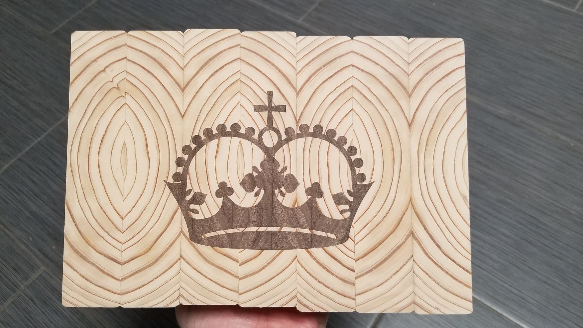
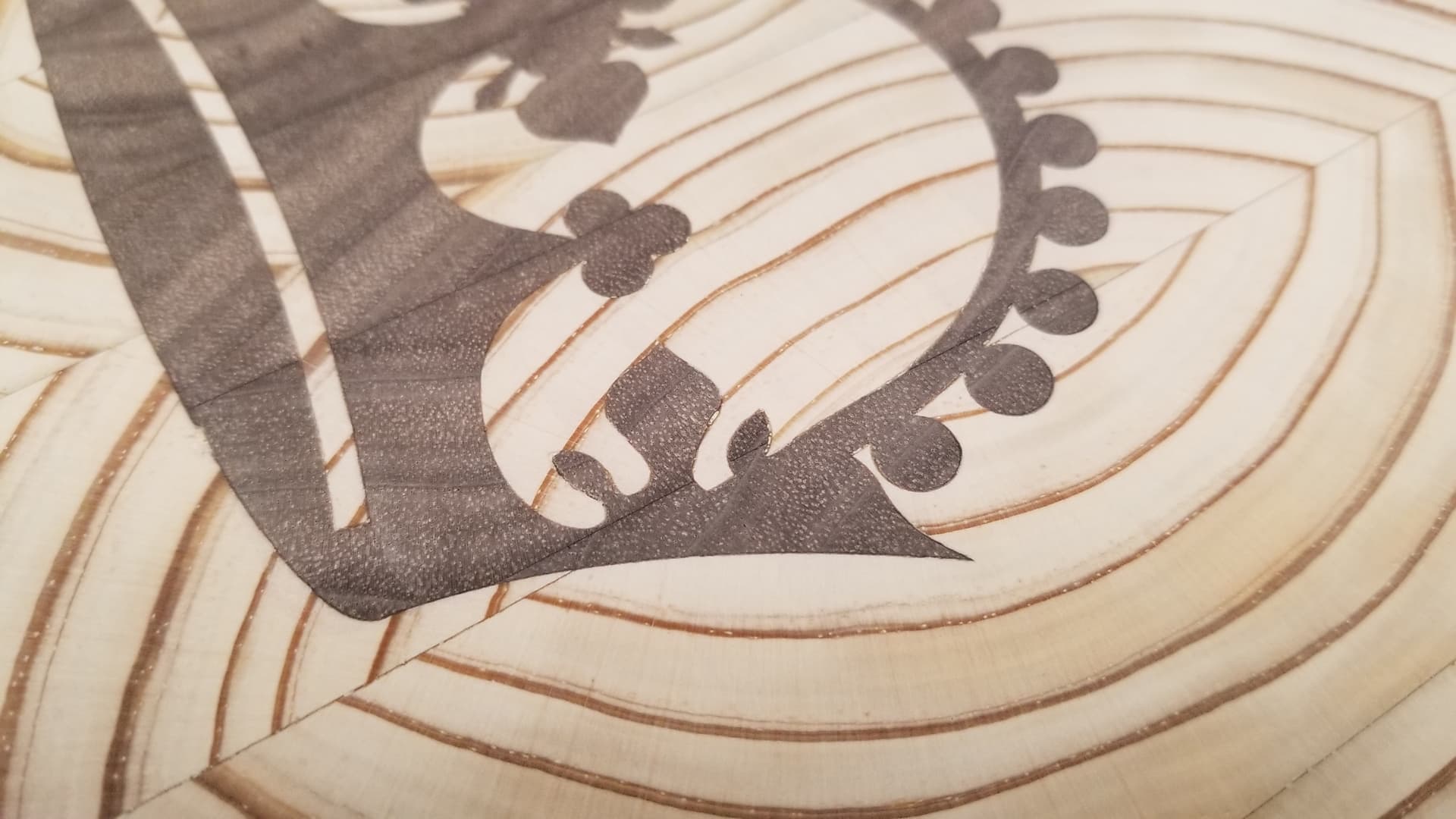
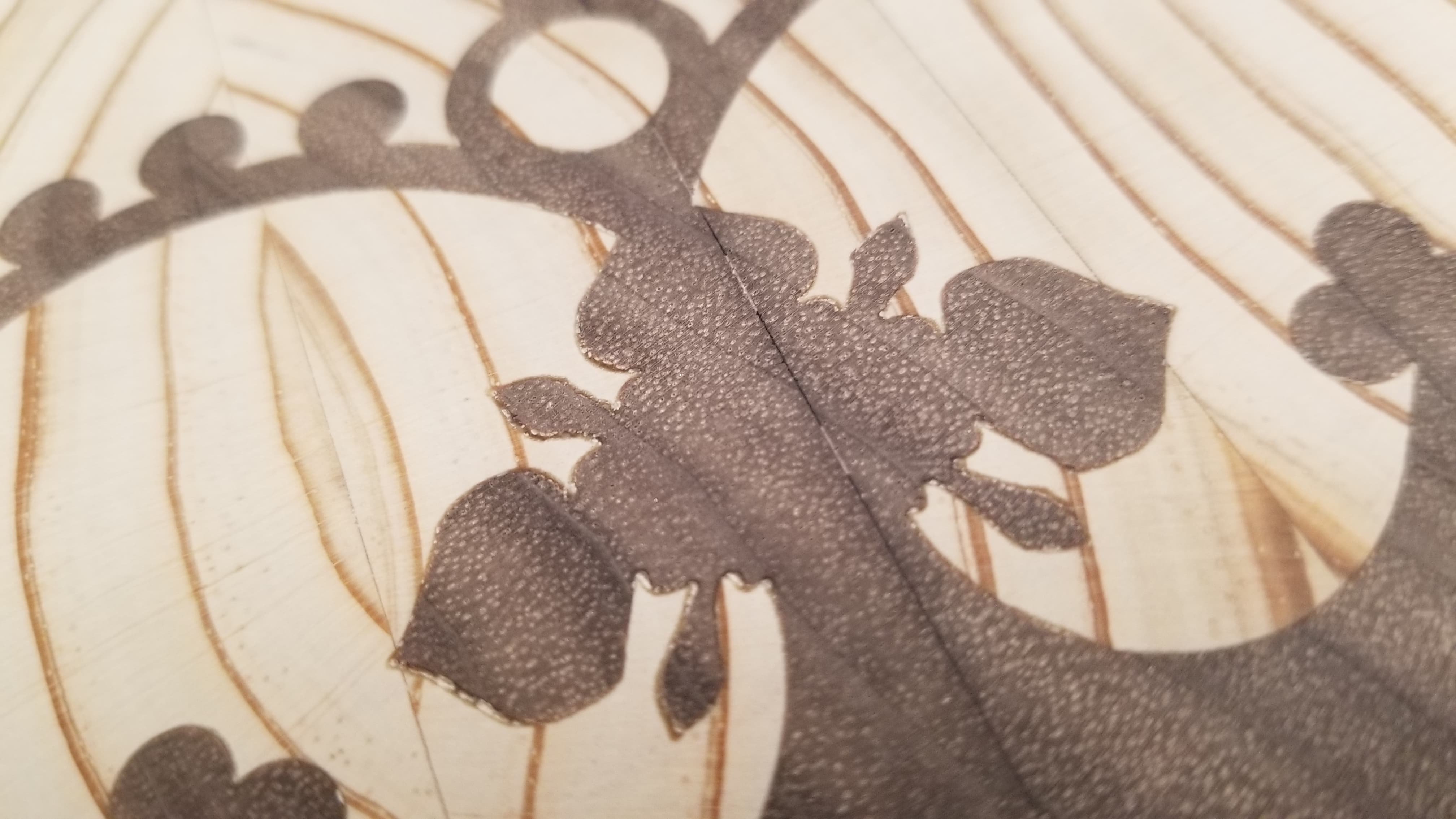
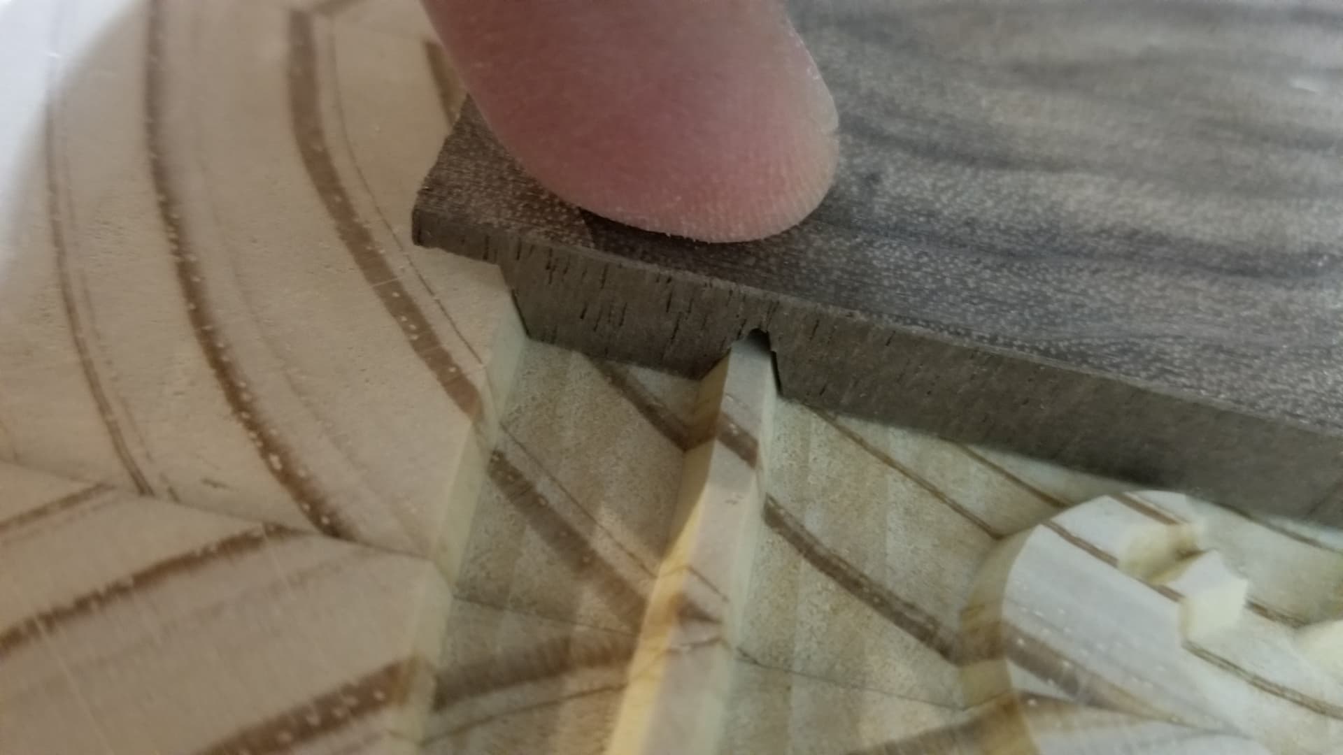
The resulting error is shown here, which I am blaming on the nonzero (effective) tip size which could be runout or something.

(The plug was actually in two halves that were butted together but not glued, which turned out to be very helpful.)

Sanding the plug is how I got it shortened to fit properly.

Edit: ok, it looks like the finishing allowance does not simply offset the curve radially. I’m not sure what it does exactly, but it might be okay as an alternative to the starting depth. I’m not sure.

Edit 2: it looks like the finishing allowance offsets vertically and not radially, but it does not affect the pocketing (for positive or negative values of allowance), so it can’t be used as an alternative to starting depth. I feel like there might be bugs where the behavior is a bit strange compared to what might be expected, but those probably belong in another thread.

1 Like

Wouldn’t you want your pocket to be deeper than your plug instead of the other way around? This prevents the plug from bottoming out in the pocket before it’s fully seated.

Not sure what you mean about vertical offset as you can see in the previous the finish allowance changes the thickness of your carves thus it should be radially. Maybe I just got lucky when I did it this way though as it seemed to work decently well the first time. Minus my clamping error and mirror error.

It is better for the pocket to be too deep than the plug to be too tall, but I would like to get it just right with maybe a small gap, so if the plug has large continuous regions, it’s supported without having to resort to spacers. For narrow pieces, a deeper pocket is just fine and probably even a good thing to give the glue somewhere to go. (Maybe need to think about something for the large areas.)

I did some experimenting with Estlcam and the diagram showed wider/narrower cuts when a finishing offset was used, but looking at the g-code preview and the g-code itself, it did not match up. In particular, the perimeter and depth of the pocketing areas did not change at all, and only the carve operations changed in Z. If your job has no pocketing areas then you might not see the difference, but if there are pocketing areas, they will be too shallow and it will collide. This is Estlcam version 11.244 and this is why I’m calling it a bug, because I would expect the behavior to be more like you described.

Makes sense, my carve did have pocketing but not with a different tool. I was able to clear it quickly with the v bit. You might be onto something though and my carve would not have shown that error

Starting depth does not really work if you have to go deeper than 4mm because then it has to cut a lot of material at once and might wobble. At least that’s my experience. :slight_smile:

I did 3mm to 6mm though, so that might have been too much. I am also shitty at math, maybe the 1mm would have been enough.

Yes, fair enough. I have only been cutting relatively shallow, and my 1/8" bit only has a few mm of cutting delth anyway. The large cutting depth is part of the reason for the importance of the finishing pass. (The other reason is higher speed pocketing.)

Also the maximum step-down setting is not applied to the starting depth, so to cut multiple depths gradually would require multiple toolpaths. Perhaps Estlcam could have a z offset distinct from starting depth that does respect the stepdown, but currently it doesn’t.

Grblgru got his insert feature working last year. He has at least one YouTube video about it.