Maybe this design is on the forum somewhere, but it was new to me. I liked there are minimal weight issues. That is someone could build a pretty heavy table, and the mechanism would still work well and not require much strength to put up and take down.
Nice find! I ain’t getting any younger that’s for sure; so this one’s getting saved. It reminds me of the ingenious design on my Bosch ‘gravity rise’ chop saw stand… worth every penny I paid for it. I love it when ME’s come up with marvelously efficient designs like that. I should have taken more interest in those ME classes in college… kinematics were a bit painful for me at the time.
Love the design. Wish I knew how the "legs’ he has underneath work (I can never install gas struts on doors either). My only other issues is leaving the gantry facing out. My luck I would catch it as I walk past and bend something or rip it out.
Thanks for posting this. I am still going to give it a good look.
With the right pivot points etc, I think this could be done without any added force assist. The geometries can be very complex to solve, but that is something most ME’s could work out I think. Having spring assist on something dangerous requires some extra thought for safety. Even the torsion springs on garage doors break over time, and that’s a pretty optimized setup with minimal fatigue. Making the mechanics such that gravity loads form the assist forces is ideal. Then you just have to worry about your pivot shafts and welds (or glue+bolts/nails for most of us).
Again, the Bosch Gravity Rise saw stand is an excellent example of what I’m talking about:
No springs or gas, just gravity and literally ~10lb force down/up on the handle to deploy/store it, with the heavy arse saw installed. You can see from the pics… it’s not very easy math to solve that problem. However once that matrix is solved… it’s all gravy from there. Imagine having a MPCNC primo in a gravity rise dolly… I’d start bringing it to my construction sites lol.
The problems I envision in doing this… you need a fixed/known center of mass. So the CNC has to be locked down while it is moved from use to storage. Also, would an mpcnc survive hanging sideways… without needing pretty much a full retuning?
My one concern here is the weight of the Z axis and the router deforming the plastic over time. I’ve had this problem with other PLA printed items. With that in mind, I’d just plan on removing the Z axis before stowing the table. It is trivial to remove the Z axis and stow it separately, and removing it would also largely address your center of mass concern.
For how long? Plastic will deform over time, and your router is likely to end up being out of square to the bed if you’re planning on leaving it that way for extended periods of time.
At what temperature? Keep it to 75-80°F (22-25°C) and it will do better than if it’s much warmer.
What are you hanging it by? If you’re going to support the table, and leave the machine hanging by the screws into the feet, you’ve got another part to worry about deforming. How tall are the legs? The lower, the better, here.
Are you willing to add external support?
This is the big one. If you are willing to add some external supports, say to the bottom rail, this will alleviate some of the pressure on the support screws into the feet, allowing it to remain true to its dimensions longer. I would strongly advise this as a minimum. Also, having a “parked” position for the core with any kind of router involved, and a support structure so that the router is not hanging from the core would be a very good idea.
For my table, I would probably do this as some sort of structure that bolts to the spoilboard hold down T nuts. Have a cradle that holds the router, and bolts down to the table, as well as some external support for the bottom rail, and I think I’d be comfortable hanging my (rather large) Primo on its side for a reasonably extended period of time.
For the lower rail support, probably it would be into the ends of the now vertical rails that I’d add support.
I think Dan hit that solution right on the head with the idea of making a storage carriage for the Z that attaches to the spoilboard tracks. That should fix the CG, and take all kinds of loading off of plastic parts. Now, I’d mostly be worried about the torque acting on those legs (weight of the rest of the tubes). In my garage this definitely would not work well. It gets way too warm during summer, and the PLA creep would be rediculous to deal with. Maybe with a not-so-printed corner modification, it could work though. I’m thinking just some substantial ply gussets to lock position of the 2 lower corners to the table (while in storage position). Just extend the left Y-rod on both ends (or right, or x rods depending on orientation… whichever side ends up down while stored), slip it through a gnarly ply bracket with some hardware to prevent any motion wrt the table. Then when tilted up, the ply would take loadings off the plastic… heck may even result in cleaner cuts too lol, but that’s treading away from the printed cnc theme.
isimplybuiltit on YouTube built a vertical storage table in late 2020. I have not seen an update about it but I have asked on the build video if there has been any noticeable issues storing the MPCNC vertically.
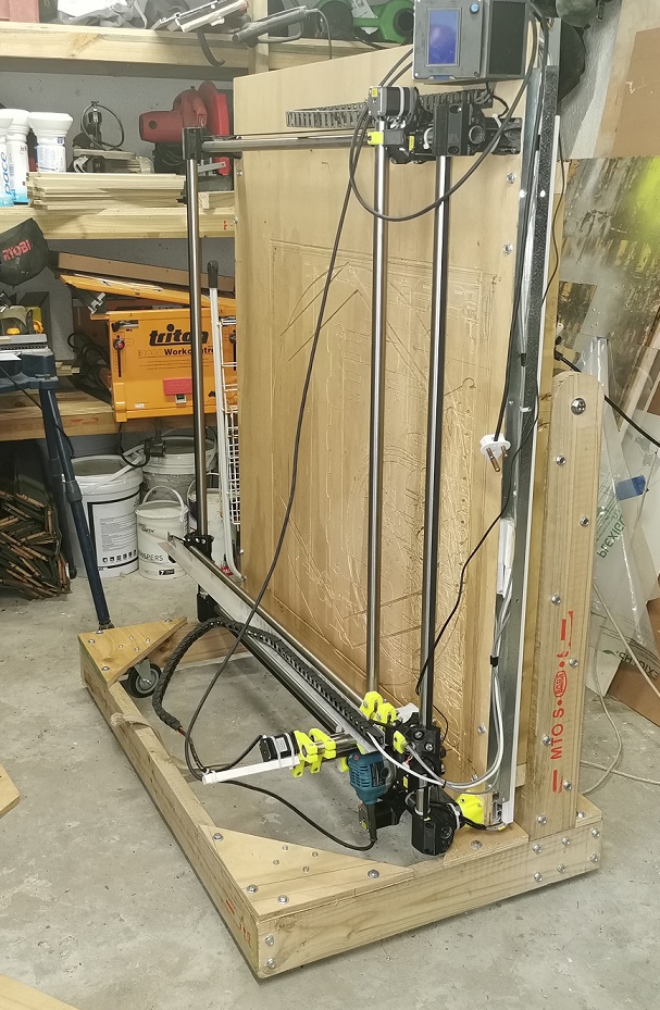
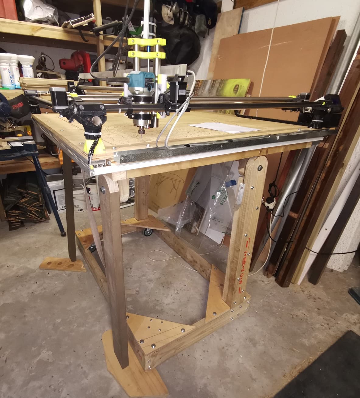
This worked for me. I had my MPCNC dictate the workshop lay out and after a few years had to make a plan. This worked for me. I can wheel it to one side, then position it where I wanted it when I needed to use it.
Nothing too fancy, just have to work out the position of the pivot and that will dictate how heavy it is to swing into position. I fitted fold down legs, then just have to space them when down to level it. The two front legs pivot and I made a catch to hold them while it folds down. Just a simple L bracket with a lip that each leg hooks on. One leg is fixed to the front of the 38x114 and the other to the back so they dont interfere with each other. I fixed an old cloth belt to allow easy lifting and lowering to take the strain off my aging back.
I have it on wheels, 2 fixed and 2 swivel so I can wheel it around as I need. That is why there is the 4 triangles on the base, the wheels are fixed to to those. They also help to keep everything square.
I used 38x114 timber as I use that in my everyday job so had lots of ‘off-cuts’ to hand. Pivots are just simple 10mm bolts with fender washers and nylock nuts. I doubled up the wood on the fixed legs for insurance. The 2nd piece is bolted to the back of the base, the pivot is on top.
Everything was made up with stuff laying around the workshop for years.
Ecotrunking used to keep all the wiring tidy for the limits and I had a piece of galvanised bent to make a channel to accommodate the cable chain.
In 2 years, it has not sagged and we have had a few 38’c days in that time. I have kept the Primo legs as short as possible though to minimise flex.