Heyoheyo, finally my build is getting somewhere, after having some time of hectic work I now have a project coming up where I will need a CNC to cut some plywood for making a few backlit signs. Still have a lot of work so I’m doing an hour here and a few there when I get bored from what I actually am suppose to do…
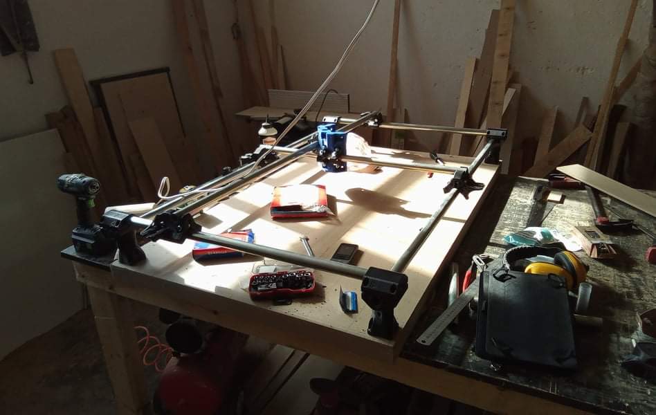
So after printing all the parts about 3-4 months ago I the day before yesterday I threw together a torsionbox from some 8mm mdf I had left from my current project, the realization of these leftovers is what kick-started me again. I had a lot of strips of 4cm left and also enough for a top.
Turns out that 4cm wide 8mm strips isn’t enough to make it stiff at all though hahaha… maybe I didn’t put enough tiny pieces… Anyway I will simply build a good and sturdybase and all good. At least it’s flat
And yesterday I actually managed to find 10mm belts and pulleys from a shop in my city so will pick that on Monday. And also bought some pipes and started assembly. I had intentions to to a pretty big one 1x1m cutting area, but I didn’t think and the pipes came in 3m lengths so didn’t work out haha… so now it’s 1x0.5m. Might scale it down after the project though if it’s way to slow and probably will use it to cut pieces for another machine later on.
Edit. Sorry for the horrible light in the photo, I’ll do better next time haha
For power I’m planning to use two 6volts power supplys in parallel (series?) to make 12v, only because I had them laying around… should be fine I believe? The are 50amps so power shouldn’t be a problem. Will probably most likely maybe upgrade soon to a proper 12 volt since I believe I will need these something else.
And for controller I’m gonna use a cncshield with drv8868 or what ever they are called, the purple ones. With grbl, simply because this is what I’ve read about for some and have a decent understanding of how it’s gonna happen.
And now my momentum is up so I hope to finish it quite soon, but no promises!
Edit. Also wondering if anyone have experience with inverting the work dimensions so that the 0,0 is in the far left corner instead of the front one? Is there any certain drawbacks except not being standard that I’m missing??
Series if you want the voltage to add to 12V. Basically the same thing lots of products do with AA batteries. I’ll leave someone else to comment and whether it is safe to do. (My intuition is that it should be okay, but I’ll also not building this and wouldn’t suffer from the fire that could occur, so I recommend that you be careful)
The input is AC and it has ground, negative and positive. That has to be shared between the two supplies.
The output is negative and positive DC.
If the negative DC output is allowed to float, then connecting the negative of one supply to the positive of the other would give you 12VDC across the remaining DC connections.
But what is also common is they will connect the negative DC connection to the input ground. In that case, you’re shorting one of the power supplies by connecting it this way. At best it won’t work. At worst, it will be a fast way to make fire.
A new 12DC 6A power supply is pretty inexpensive and very common. I would recommend buying one.
That should work fine. For 16th microstepping, it should be 100,100,400 steps/mm. For 32nd, it is 200,200,800. Keep your Z top speed under 10mm/s to start. The XY can go fast, but start at 50mm/s. Acceleration is pretty dependent on the weight of your machine.
It has to be a right handed coordinate system. As long as you can stand somewhere and +X goes to the right, +Y goes away and +Z goes up, it will be a RH coordinate system. If you make a left handed coordinate system, things will be mirrored.
It should match your settings in CAM. In Estlcam, the default is for X to be right on the screen. If you flip stuff around, the machine will cut rotated patterns. It isn’t impossible to just imagine yourself standing on the left side of the table when doing CAM though.
I’ve actually already connected them and they output 12v DC, can’t remember exactly how but maybe like you suggested, and they have already been used lin this setup for another little synth project I started a while back so I know it won’t catch fire or so. And it’s quite high quality supplies, not the cheapest.
Was more thinking if there is some increase in noise or something that could create a problem, but yeah I’m the end I will probably buy a dedicated power supply, let’s see.
Thanks for the speed and setup recommendations, I’ll start there and work my self upwards.
And not sure I’m following your right-hand/left-hand lingo. If I remember correctly in the buildguide it suggests that the 0,0 is in the left down?? Shouldn’t that make it a left-handed system?? With the thumb being the X?
Good. So they haven’t connected the grounds. That should be fine. The motor drivers are very noisy. The digital stuff all runs on 5V and the power noise is well filtered. So that will be fine.
I was taught this is physics class. I am not a trained machinist. So sorry if it doesn’t quite follow common sense. The important thing isn’t the names. It is just important that everyone uses the same thing to describe them.
It has more to do with the way your hands naturally make that shape than the left or right of the machine. You can rotate or move your right hand any way you want and the coordinates will still follow the right hand rule. So putting you right hand on the left side of the machine, making that shape and assigning XYZ will make that a RH coordinate system. A left handed coordinate system is just a mirror world of the right hand ones.
If you want 0,0 to be in the far left. Let’s go through what the consequences would be:
Imagine yourself standing on the left edge of the machine. From that perspective, X+ would go right, Y+ would go away and Z+ would go up.
Now go back to the edge you took the picture from. That means that right is now Y+. And away from you is X-. Z stays the same.
Whenever you are using estlcam (or the jog controls), you have to imagine standing on that left edge of the table when laying out your parts to cut. Because the X and Y in Estlcam are set up that way.
It would totally work. You would get used to it quickly (humans are amazing).
Yeah the Arduino will be running of the USB so the 5v isn’t a problem.
[spoiler]
*And I get your hand thing now and remember I've heard it before. But actually the software I use for all my designing (rhino) is left handed, y is away but x is from left to right. But now when I think about it the last CNC I worked with was configured like I want it and the one before that was configured like the right hand haha.. I guess everything is possible. But the sideways axis(as I'm imagining it atm it's the long axis on my build doesn't really matter though) I don't really care about, but the short one I want to move away from me.. *

*And also atm it's just sitting on top of my workbench, not it's final position or orientation, not even sure yet if the core is where I want it hahah, just threw it together in excitement. I will update with a more well formulated question when I'm closer to needing a solution, that I really don't need actually, I can simply put the machine to the other wall and as you say get used to it being like that. *

*But basically would like to flip one axis, minus is plus basically and there by have it towards my intended wall and also not cut mirrored because knowing my self, I'm gonna waste alot of material if I have to remember to mirror everything before calculating the gcode...*
[/spoiler]
Edit. Thought about it some more and I now see that both machines were set up the same… Just flipped around and I will simply have to do as you said, remember that I’m not standing where the computer is standing… thanks for clearing that up!
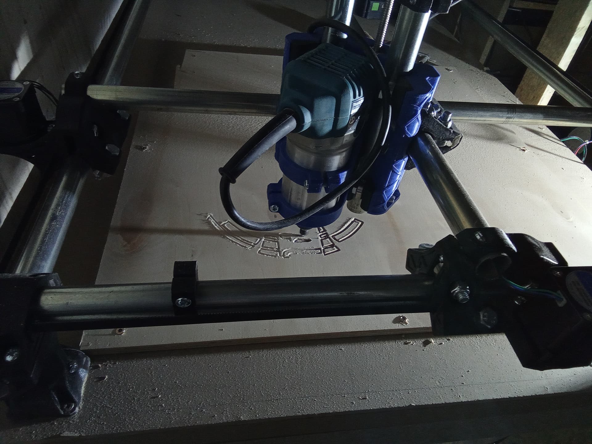
So I got it up and running! It’s atm working 200mm/min at 1mm DOC, or around there… the stock I had laying around wasn’t completely flat… But the z plunge rate is breaking my heart haha, how fast do you guys actually keep it at??
And I’ve also realized that my buddy can’t really go back to zero, not sure why. It’s off with a 2-3 mill… Any ideas?
The frame is dead on square as far as I can tell, for sure within the millimeter and the trucks/coreI got it quite square, at least within 1.5mm so I thought the motors should be able to keep it… maybe my vref is low though. At 0.7 atm, will check after this cut how the steppers feel. Could that be the reason though?
My first guess would be the power cord. Move it to a different angle and zip tie it up a bit. I usually take the strain relief out and get the cord even further out of the way.
Ah yeah, now when you mention it that makes sense. I actually reconfigured it after and the 0 is now in the opposite corner and it seems better indeed.
Another thing I noticed today that seems odd to me when I was cutting a 100mm rectangle with 5mm depth. The Z steps were way off and are now on 1600 instead of 400… I thought 400 is for 1/16th steps? That kind of explains the super slow plunge rate I was experiencing, it’s not so bad anymore haha
Yeah I realised this aswell, I have a 2mm screw… haha but should be fine I guess??
And also realised why my machine was so slow, I didn’t realize that here everyone is writing mm/s just assumed it was mm/m hahaha a bit more reasonable now
1 start leadscrew have some advantages. But you lose top speed in Z. Something like 4-5mm/s max on the Z or you will skip steps. Just pick a setting and make it top speed with M203 and save it with M500. You don’t want weren’t CAM sending your Z screw flying.
Yeah, I have it at 5m/s, seems fine, good idea to lock it in firmware though, will do
I noticed today when surfacing my spoiler board that I need to tram my buddy a little, is that done by squaring the core as described in the build guide?? Or is shimming the way?

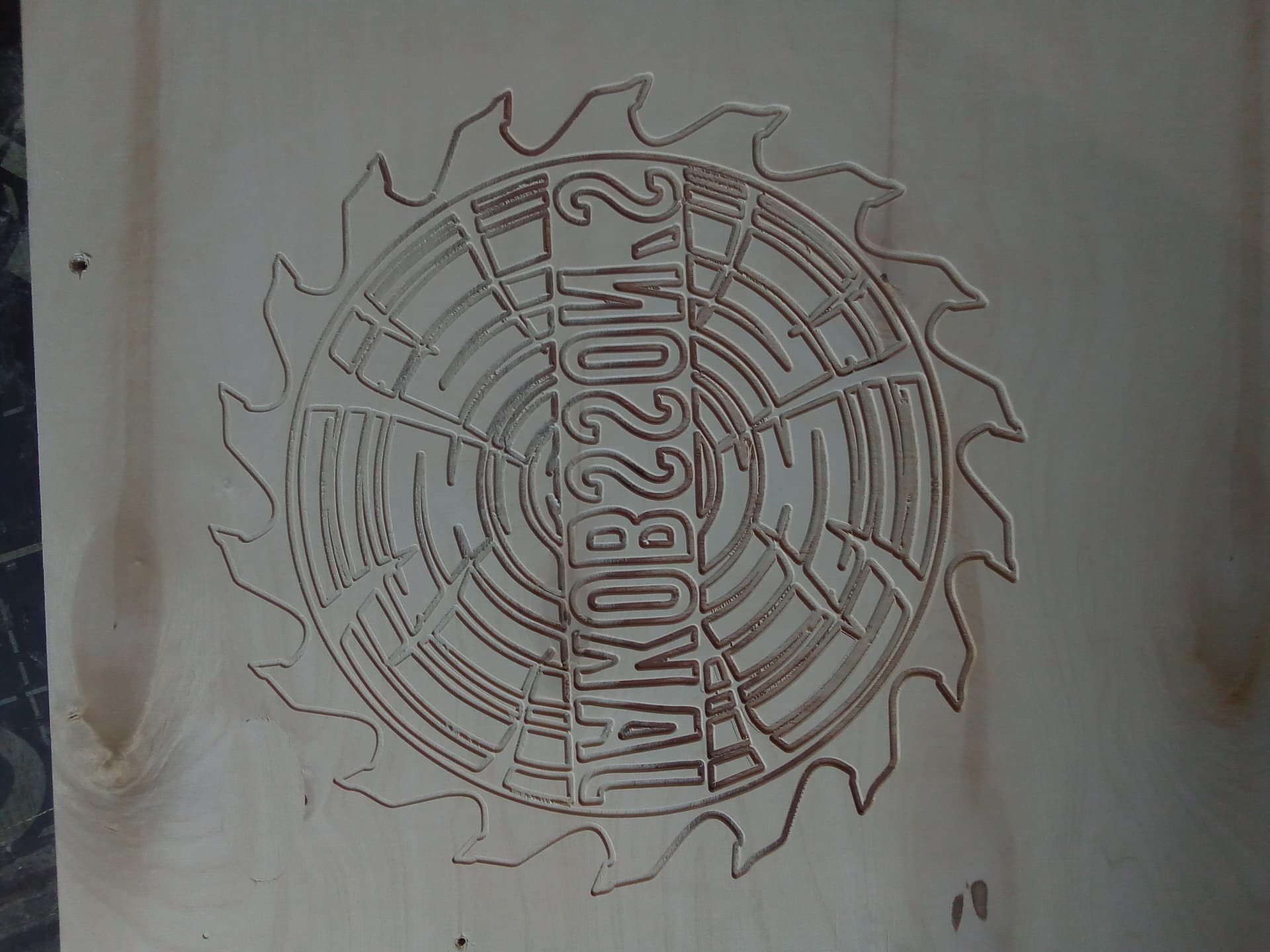
 and to small for the bit I have atm but other than that, highly satisfied! Job well done


