A primer on stiffness

TLDR; A tube’s stiffness goes up with the 4th power of radius, but weight only goes up with the square. For a LowRider build, the 1.25" x 0.49" DOM steel tube from speedymetals.com should improve stiffness and reduce weight.


I’ve been reading the forums the past few days and thought I would chime in. My background is as a Mechanical Engineer and I hope there are some things I learned and applied in my careers which could be useful to this incredible community.

To paraphrase another poster, there’s “math” and then there’s MATH. This post spends more time on the latter, and should give a brief primer on the underpinnings of simple design choices.

Terms of the art (in particular stiffness)

Discussing this topic is hard because the terms have a scientific meaning and a colloquial meaning. There’s enough overlap that we confusingly talk about one when we mean the other. For instance, stiffness is an extrinsic[1] property of an object. If you slice a board in half it loses stiffness. Elasticity, on the the other hand is an intrinsic[1] material property. If you cut a spring in half it is just as springy. However, you will frequently hear stiffness to refer to a metal, and that’s just language being messy. So in order to clear up confusion, when I mean a material’s intrinsic quality, I’ll refer to it as stiffness (MOE) even though we know I really mean Modulus of Elasticity[2].

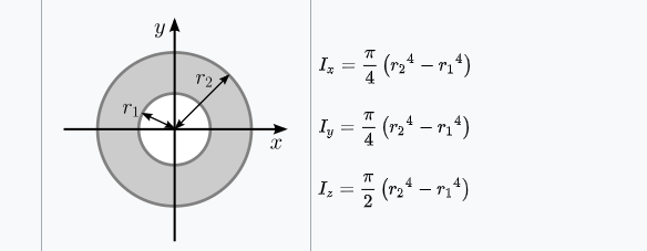
There’s also the term bending moment of inertia, which is easily confused with other similar equations, specifically rotational moment of inertia[3] and section modulus[4]. Since these basically differ only in the exponential, it’s easy to confuse them and yet get radically different results. Any time I refer to inertia I mean “bending moment of inertia”.

So what makes something stiff?

It’s a combination of shape and material. If the material is stiff (MOE) and the shape has high bending moment of inertia, then the result will be hard to bend (i.e. stiff). If you take the same material and make a low (bending moment of) inertia object, then it will be less stiff. This is why rods are much less stiff than tubes.

Stiffness is linear with inertia. If you double inertia, you double stiffness. However, inertia increases with the fourth power of dimension. So if you double a rod’s radius, you increase the inertia (and thus the stiffness) by 2^4 = 16 times!

Screen Shot 2020-03-15 at 19.38.50

The cool thing is that at the same time you only increased weight by 2^2 = 4 times (because weight increases with area). So going up in radius is hugely beneficial relative to weight.

Another neat thing about calculating both weight and inertia is that they are “superpositionable” calculations. In other words, weights can be added to weights and inertias to inertias. Where this comes in handy is that you can add “negative weight” and “negative inertia”. In other words, you can calculate the weight and inertia of a tube by adding the weight/inertia of the positive outside diameter and then SUBTRACT the weight/inertia of the missing inside diameter.

Here’s a simple graph showing relative inertia for tubes of various ODs and wall thicknesses which are available from speedymetals.com (DOM steel). I’ve referenced everything to LowRider’s default 1" OD x 0.065" wall thickness, so if it’s to the left it’s lighter and if it’s above it’s stiffer.

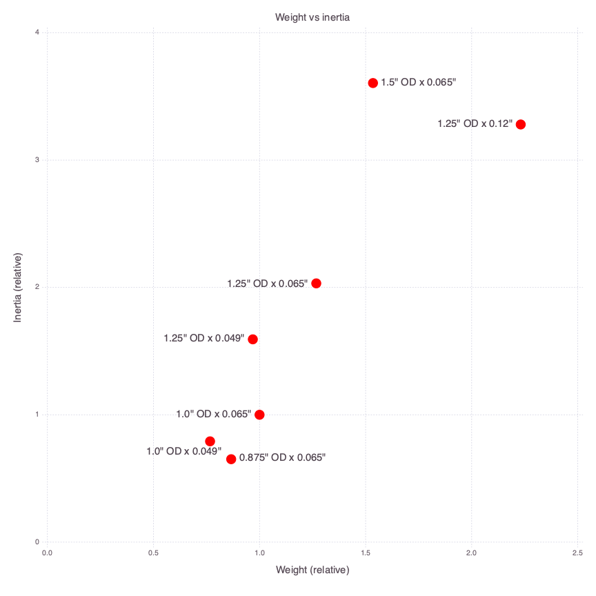
We can see that 1.25 x 0.049" is a potential winner! It’s lighter (faster machine movements) and stiffer (less deflection). The downside is that the wall is thinner, and this could lead to flattening of the tube if the forces are too high.

And if you wanted to go significantly stiffer for not much increase in weight, the 1.5 x 0.065" is a strong candidate.

Now, this is MATH. The real world is going to closely track this, so long as everything else is as perfect as the MATH. (Hah!)

In the real world, you’ll get various grades of metal, alloys, and treatments. All those factors impact stiffness (MOE) and can easily sway the resulting numbers by ± 20%. Which is how EMT can have a higher inertia but an overall lower stiffness.

Why do real-world tests show such variation?

This can be completely chalked up to materials, tolerances, and fabrication. It’s why it’s so important to find quality suppliers, and why it’s hard to compare across suppliers, stores, and shores. And to test, test, test. Because MATH hints at, but does not equal, REALITY.

Follow up thoughts:

Should we talk about strength?

Nope.

It’s only relevant if the parts are breaking. As @vicious1 has written in other places, he’s seen calculated loads on the order of 1-2kg. Until the loads get 100x higher we can safely ignore strength as an issue.

Fun fact: all metals have about the same stiffness (MOE)

It’s just one of those peculiar qualities of metals. Like almost all are silver-ish (Copper and Gold being the exceptions).

So most metals naturally have similar (within an order of magnitude) stiffness (MOE). That means that careful choice of metals is essential because quality, alloy, and treatment make a big difference.

But what about titanium? It’s pretty magical stuff, right?

TLDR; Titanium alloys are only better for us when the tube dimensions are larger than the equivalent for steel.


Titanium is awesome, but it’s not a magic bullet. Titanium is very tough. It has an incredibly high rupture resistance vs steel (1080MPa vs 300MPa), which tells us that it really doesn’t like to break. And it’s much harder than steel (3700 Mpa vs 2100), so it wears much better.

However, it is not as stiff (MOE) as steel (200GPa vs 120Gpa) and it is not as light as aluminum (2.7g/cm^3 vs 4.5 g/cm^3). So for identical dimensions to steel (or identical mass to aluminum) it’s going to perform worse in a stiffness application. If you can get larger-diameter thinner-walled titanium tubing than it winds up being stiffer AND stronger AND lighter AND higher wearing. But only because you got it BIGGER.

What about carbon fiber?

It’s great stuff in the right application! Stiff(MOE) as all get out and light as a feather, but it has very poor wear characteristics and does not fail gracefully. It’s the same game as titanium; you can get lighter, stronger, stiffer so long as you go BIGGER.

What about XXX?

I’m happy to discuss XXX in this thread. I’ve seen ideas such as:

  • pretensioning
    • unfortunately only works when you want to avoid a material changing from compression to tension. Sailboat and bridge rigging qualifies, but the case of a CNC gantry does not
  • filling in the tube
    • decreasing returns by a power of 4, so you quickly add weight without rigidity
  • using other cross-sections
    • much higher inertia, but at what cost? It’s been described elsewhere in the forums how important the round tube’s symmetric profile is for ease of alignment and calibration.

Throw some ideas out there, there are no bad questions and the worst that will happen is we’ll all learn together.


Footnotes

[1] Extrinsic properties are, roughly speaking, properties which change if you cut something into parts. For instance, a board’s length is extrinsic because if you cut it in half, it’s length changes.

On the flip side, intrinsic properties are things which stay constant even if you change the quantity of material. A board’s density does not change if you cut it in half, a glass of water’s temperature does not change if you pour half of it out.

[2] Modulus of Elasticity, aka Young’s Modulus, is a scientific term which, roughly speaking, tells us how far something will deflect for a given force. If the MOE is twice as high, the material will deflect half as much. If it is twice as low, it will bend twice as much. MOE goes from really high for graphene (1,000GPa) to really low for rubber (0.01GPa). So a rod made out of graphene would literally deflect 100,000 times less than the same rod out of rubber.

[3] Rotational moment of inertia is roughly speaking how much energy is in a spinning object. We all know that a bike wheel is light but has a lot of spinning energy whereas a solid wooden block is a lot easier to stop spinning.

[4] Section modulus is used to determine at what load an object will break.

13 Likes

Thank you for taking the time to post such a thorough and well-written explanation!

I’m curious about how plain 3/4" EMT (0.922 OD x 0.065) compares to 1" (0.065) stainless. I know the stainless is SO much harder to drill holes in…but it sounds like you’re saying there’s negligible improvement for our needs.

If I did my math correctly, 1" SS is 28% higher MOE than the EMT. (.0115 vs .0089)…but it doesn’t matter that the material is SS. Right?

I’m glad you enjoyed it! Lemme see if I can answer your questions:

I’m going to split your question into two parts. First is the shape and the second is the material.

(Remember that MOE is a property of the material, and inertia is a property of the shape, i.e. dimensions.)


Bending moment of inertia for EMT

You’re on the right track but I wonder if your calculations are fully correct. Did you maybe use diameter^4 instead of radius^4 when calculating inertia? Here’s what I have:

I_emt = pi/4*((.922/2)^4 - (.922/2 - .065)^4) = 0.0162
I__ss = pi/4*((1.00/2)^4 - (1.00/2 - .065)^4) = 0.0201

0.0201/0.0162 = 1.3 → 30% increase when going from EMT to 1".

That’s such a huge change in inertia for what just an 8% change in diameter. That means that for an identical material (and thus identical MOE) you wind up with a much less stiff tube with the EMT dimensions.

Modulus of Elasticity for EMT

So we know that the inertia for the 1" tube is 30% higher, what about the relative stiffness (MOE) of the materials? This is somewhat harder to calculate, because we don’t know the alloy and need to guess a bit. I’m guessing from your comment about drilling that this is probably mild steel with galvanization. Googling on bing.com suggests that it’s around 200MPa, which is right in line with SS. So from this perspective, EMT and SS tube don’t significantly differ.

It really comes down to that tube diameter.

Is this consistent with real-world tests?

A 30% change in inertia with 0% change in MOE means that you would expect 30% more deflection for the same load. And that’s exactly how we go from having a tiny deflection we can hardly see to something that’s really noticeable. If you haven’t seen them already, check out the visible difference in the tests for EMT and SS, both with 0.050" wall thickness: Stainless Steel - Quick and dirty flex test

1 Like

Thank you for this. Great reference.

Can this be put in turms I can understand and a short synopsis of what is better and why

Good information. There is a caveat to the stiffness of a tube being the 4th power of the diameter, which is that it applies if the wall thickness also scales with diameter. For a fixed wall thickness (and for thickness much less than the diameter) stiffness will be closer to the third power (and weight linear), but in any case it doesn’t change the fact that the tube diameter is the major driving factor.

I suspect that 0.049 is thick enough to support the bearings without flattening, even on large tubes. On speedymetals I looked for the largest tube they have with 0.049" wall thickness and it looks like 1 3/8" is available, while anything larger like 1.5" is only available starting at 0.065".

I was able to reproduce your calculations and extending to 1.375" with 0.049" wall I am showing it would have 2.14x stiffness and 7% heavier than the baseline, whereas 1.25" is 1.59x stiffer and 3% lighter. Same idea, going to the maximum radius for that wall thickness.

For my part I would love a parametric model that accepts any tube size, because the cost to me is zero and I can “optimize”. But at the same time I appreciate that there is a cost to Ryan in the proliferation of variants and more broadly the “optimization” attitude. This is a separate topic so I won’t rehash it here.

There are also the practical aspects to the complete system, where belts stretch and the table might not be very flat in the x direction, and sheet goods are likely to deflect to match the table anyway. The main reason not to use larger tubes is not that it’s not better, but that in the grand scheme the relative benefit is not so compelling.

I hope this doesn’t sound negative. I agree with your breakdown and I think the education is helpful. Thank you for that. :+1:

Bigger tubes resist bending better than smaller tubes. :grinning:
Switching to stainless results in a stiffer machine, but mainly because the tubes are slightly larger, not because the material is ‘better’.

The difference between the smallest (EMT about 0.9") and largest (1") sizes is more than you’d expect, but not huge.

IIRC (and maybe Kenn can confirm this) deflection is proportional to length cubed, so a MPCNC made with stainless steel tubes could have 10% longer X and Y dimensions than one made with EMT.

1 Like

Thank you​:exploding_head::exploding_head::exploding_head:

@jamiek, exactly! There is no such thing as a free lunch, and even something like the 1.25 x 0.49, which is both lighter and stronger than 1" x 0.065, leads to compromises because now the overall machine dimension has increased by 1". I’ve asked @vicious1if it’d be possible to easily regenerate the parts, and I wouldn’t be surprised if the answer is no. An inch is quite a significant stretch on something only 10" wide.

This is getting off-topic somewhat, but there’s also the very real likelihood that a stiffer x-gantry doesn’t solve any real-world stiffness issues. I had a colleague who would talk about improvements which are “measurable but not noticeable”, like swapping out a 0805 resistor for a 0603 resistor to save .001g of weight on a 5kg drone. Yeah, we can quantify the change but does it matter for the end user and is it worth exerting a single erg of energy to do it? (Narrator: it doesn’t and it isn’t.)

Getting really off-topic here, I would like to have more insight into what issues are most impacting the routing/carving/milling quality. It seems that a handful of the lowrider/MPCNC builds on this forum are good enough to do some serious Al milling, which gives reason for hope. Perhaps the limitation to taking everyone to that next step is a single part optimization, and not a whole machine redesign.

Ahah, now you’re getting into the hard stuff. Maybe I should write a primer on deflection as well? A layman conversation becomes harder, but more worth-while, because now “stiffness” picks up a third meaning.

The first is “stiffness” of a material, which means MOE. The second is “stiffness” of a profile, which is a purely 2D cross-section. The third is “stiffness” of an assembly, which is a dynamic deflection across 6D (x-y-z AND roll-pitch-yaw). And the thing about going from 2D to 6D is that it’s not just 3/2 = 50% harder. It’s more like 6!/2! = 60 times harder.

However, the rub is that deflection is the only thing we really care about, because that’s what directly drives machined part tolerance. It’s the end benefit which is the sum of all the machine’s stiffening features.

1 Like

Yeah, I would temper this whole thing by pointing out that spending more money on a machine that cuts just the same (or noticeably the same, by your definition) is a worse machine.

There are a few (less than 10%) of LRs that are larger than 4’8’ work area, and they have actually been successful too. It would be very hard to expect a huge machine like that to have an easy time with aluminum. But there are other reasons why that doesn’t make sense. It would take days and a lot of money to make something from Al that is that big.

2 Likes

As I understand, stiffness also decreases with length to the third power. So if you have a 1m long tube with a 25mm diameter, it will be as stiff as a 2m tube with a 50mm diameter (assuming the same wall thickness). The weight of the 2m tube will be roughly twice the weight of the 1m tube.

What I haven’t looked into yet is roll-pitch-yaw. With “traditional” gantries of CNC machines, there is a large square tube moving over the workspace, with the Z axis mounted to that tube. If there is a lot of force on the end mill, I understand that the tube can twist. Does anybody know the formulas for how many degrees of twist you can expect given the tube and the load or something?

So does this all mean that Ryans next version of the MPCNC will be 1”EMT?

1 Like

4inch just to get ahead of the demands :crazy_face::crazy_face::crazy_face::spider: sorry it hasn’t been released yet​:sunglasses: stay tuned

The mpcnc doesn’t rely of the twist (or resistance to twist) of the tubing. It uses second tubes across the table to keep the gantry from rotating. The LR has two tubes, several inches apart.

Oh man, you are telling :fire: in a :movie_camera:

1 Like

Yes I know, I was just wondering about the math.

I would assume that tilting of the Z axis on the lowrider is caused by deflection of those two tubes (one deflecting down, the other up, I guess). If so, I understand the math behind that already.

Every time I walk past some scaffolding on a building site, I wonder what a double size MPCNC would be like with 2" tube…

I know it’s pointless, but I can’t help myself…

So does this all mean that Ryans next version of the MPCNC will be 1”EMT?

I doubt it, as 25% longer tubes would require about twice as much printing (assuming that print times scale with volume). There are plenty of bigger, heavier, more expensive designs out there already. The real strength of the MPCNC is that it’s cheap and easy for a beginner, and strong enough for most of the things we want to do.

2 Likes

My printer prints while i work and sleep, so no problem there for me.

1 Like

I knew I was going to need to sit down and pay attention for this one. Thanks Ken for the definitive guide to rails.

Lots of little things to answer here, and more to add I suppose. I am going to start by saying I feel the largest problem is not really the rigidity of the tubes but the design itself. For the LowRider we have two main axes to deal with.
1)Y, along the table direction is the weakest (low hanging fruit). We/I have made a torsion spring between the two rails. I can make the build significantly stronger by making the rails further apart…or slightly stronger by increasing the diameter of the rails. We have a lever created by the tip of the endmill and half the distance of the rails, so I suspect (without doing math) a few centimeters wider would make this as rigid as larger rails.
2)X, along the rails this is where direct comparisons can happen…and we have two rails. The lever arm here is a more direct comparison to the figures you added. This is already significantly stronger than the other direction.

So, leaving Z out of it. Raising the tip of the endmill as close to the rails as possible for every cut decrease the lever arm an increases rigidity in both axis for free.

At some point the joint between the Z rails and X rails will be the weakest point.

Larger rails take more print time, and a larger table, longer belts, higher shipping costs, harder sourcing…balance. Thicker side plates to handle any extra weight.

But no one wants the boring answer. Redesigning the machine…

While CAD is parametric, it is not as easy as changing a diameter number and getting the entire assembly to update, generate new STL’s orient them properly for printing, generating new rails and table calculators, bill of materials, and instructions that are ambiguous and still clear. Any design will have limits and to make it extra parametric it would end up being a much more simple/basic/boring design. The more simple it is the less operations that can fail during resizing. It can be done but the second that happens some one will want a 4", then a 6"… and new size requests will come in everyday. I do not have the skills currently to use a free CAD program to let people generate it themselves. Not to mention I really do optimize every design to minimize print time and maximize rigidity and for each size that does take a lot of work.

Exactly. Designed for the intended purpose, speed is the very last item on my design list. It cuts wood I am very happy, above that is a bonus. I also need to be able to ship it internationally in a relatively small box, my whole machine kit can ship for less than the waste board of other machines. International source-ability and compatibility also gets factored in.

You would think everyone feels this way, yet from day one to this very day how long it takes to print is always mentioned like someone has to sit there and do it by hand…This does bug me. In the new build I am working on I am taking steps to decrease print times while increasing part volume. Print time is commonly mentioned before capabilities…This bugs me even more.

In the end for both machines one slight step up in size might happen but I would only do it to the next size of EMT, DOM and SS are just to expensive and hard to source and that is not my design intent. I really get a little bummed that I made the LR not out of EMT. People asking where to buy SS is a little gut punch for me, design failure on my part. EMT will take the build cost down buy about 25%…let that sink in.

9 Likes

Thanks, this was highly educational. You’ve given a lot of food for thought, and helped me understand where it’s worth spending time and/or analysis. Redesigning is no fun. I usually have patience for optimizing a single part as a way of customizing my build.

Have you given much thought to inverting the placement of the Z and X tubes? This would greatly reduce the torsion spring, at the cost of decreasing Y stiffness at the X-Z joint. That might be an overall victory? If that joint’s rigidity is a problem, I can see a few ways to stiffen it without getting in the way of anything else.

Smaller Z tubes would also allow to grow the X tube spacing without affecting overall machine size. Could a design using EMT with a smaller dia. Z and a similar sized X be viable?

Aha, the money shot! Knowing your design intent-- and challenges getting there-- really put stuff into perspective for me. What I get from your comment is that the bottleneck is price, not quality. Therefore, the most valuable optimizations are the ones which increase accessibility, not performance, right?

1 Like

That increases the height of the Z axis, so the wheels would have to ride on a surface other than the spoil board. No way to clamp under without adding height.

Higher part count, cost and complexity to gain something that can be gain by just increasing print time…but both would require an even longer table to accommodate.

No, but I do not want to decrease accessibility in anyway. We have a machine that cuts wood perfectly, so any added cost will surely have diminishing returns. I am completely satisfied with what we have I would be happy to decrease the price, and complexity if it meant keeping the same price point and performance. Anyone can throw money at a problem and eventually get a solution. What fun is that? I have people asking to take out a bag of screws or a couple bearing to decrease the price point because they have them on hand. That was me, I could not scrape together enough money for a shapeoko. I do not want to lose those people. $20 is not much for most but that kid in his garage mowing lawns to try and buy my kit is the target audience, also it keeps it approachable for people that are intimidated by all this high tech stuff and may or may not end up using it a ton.
At no point without doubling or tripling the price will we see a substantial increase in performance, so I guess I would rather have fun with the makers than cater to the high maintenance spenders…

The LR was born because people were pushing the limits of the MPCNC in a way that was almost making the design look bad. I made the LR in a weekend, then V2 got optimized, it cut slightly faster, was much less complex to build, lower part count and ended up costing less. So performance is the goal but I love the current price point.