First let me thank you all for your effort making this DIY project understandable to a wide range of people and for your support running this forum.
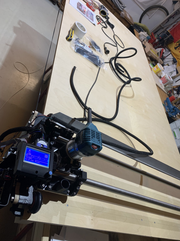
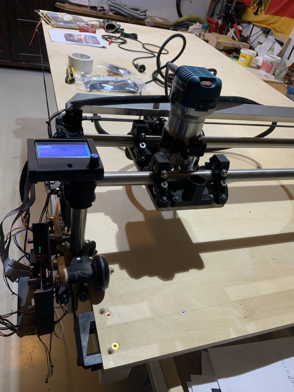
I’ve managed to build my lowrider 2 after starting to learn about it just a few months ago. I’ve attached some pictures, although I have not yet finished assembling.
The good news: the machine works, I have attached cables and power - very axis is moving as I think it is intended to. While I am getting the cables at their final place, I have encounter some uncertainties that I hope someone could clarify for me / confirm.
I suppose the axis (according to a youtube video) as following: x (along the rails), y (along the table), z (height from the table). With +/- I am not sure - here I would appreciate some advice. The following picture shows my router moved to the very - - of all three axis, as I understand it.
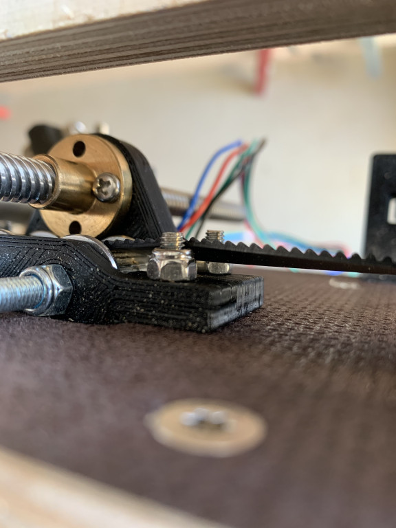
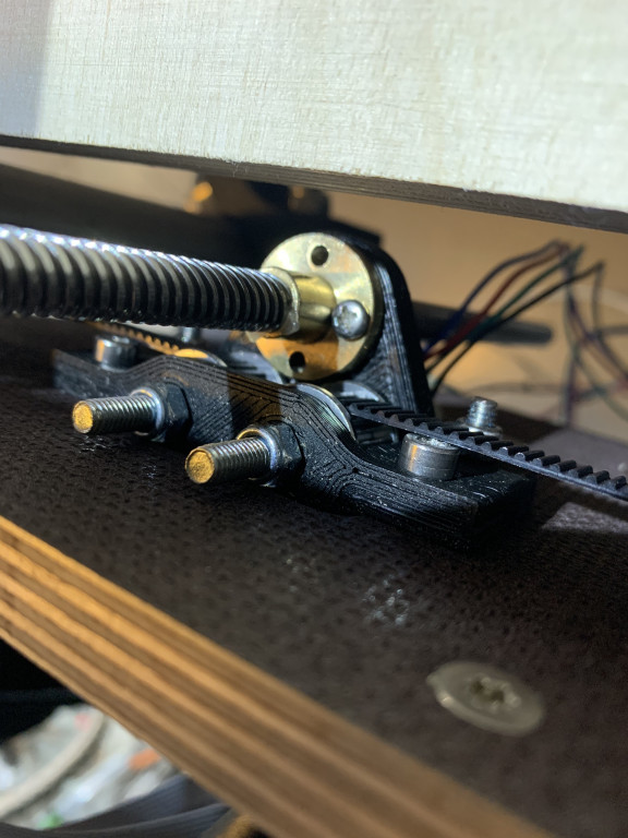
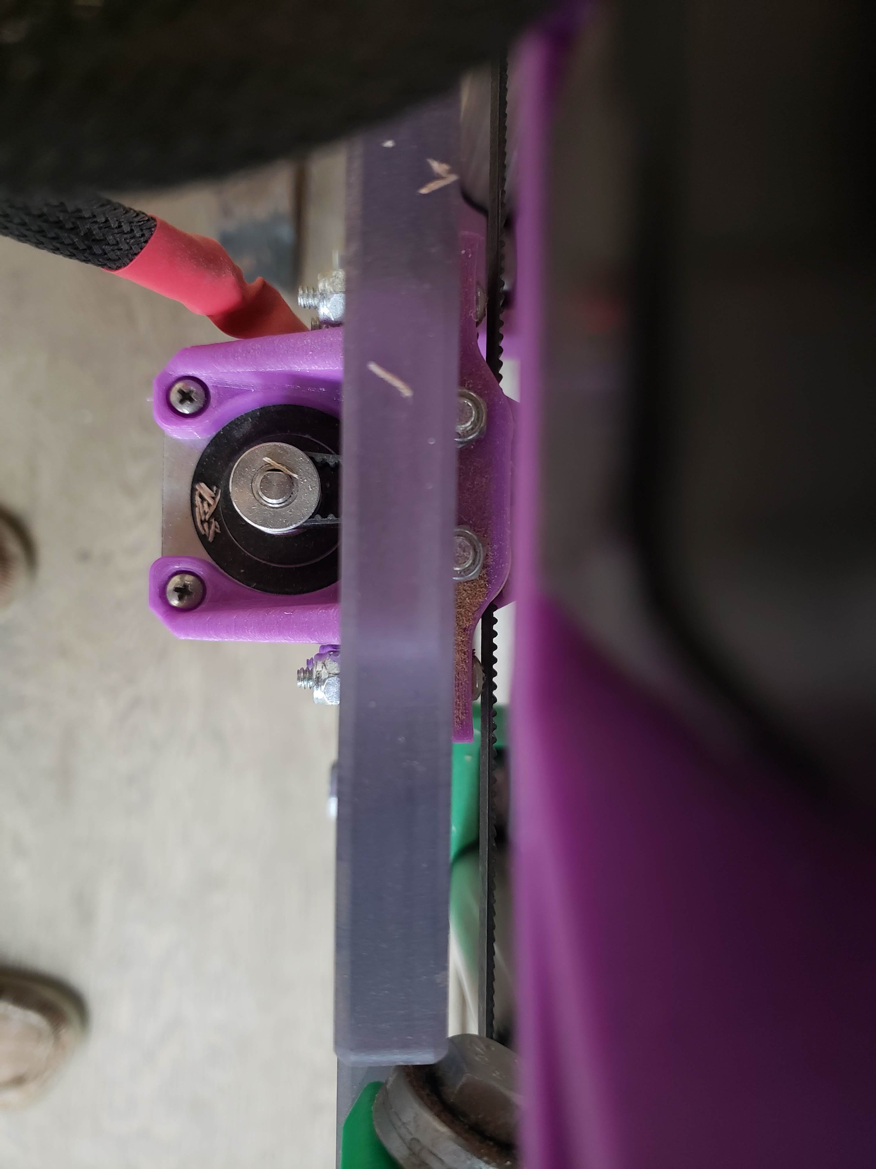
I have encountered some issues with the y-belt. Worked around it by flipping the bolts, but the y-belt ist still touching the bolt. Is that due to a mistake that I have made?
It looks to me like you have the axes all arranged and moving in the proper directions as designed.
Which axis is designated X and which is Y is somewhat arbitrary. I have my Lowrider X and Y axes switched relative to Ryan’s directions. The default configuration produces a “Portrait” view of the work area (taller in Y and narrow in X). I preferred a “Landscape” orientation (wider in X and short in Y). This is strictly a personal preference. The landscape orientation just feels more natural me.
Regarding the bolt heads touching the belts, I have pan head (rounded) Phillips machine screws in that location. These have a lower profile and do not touch the belt, although they are very close. I bought my hardware as a kit from the V1 store, so this would seem to be the recommended approach.
thank you very much for clarification. I guessed that much is depending on personal preference but did not want to screw sth up while making testing the machine. I now have gained a better understanding.
I’ve also bought the kit from v1, but not the bolts, nuts and the wooden parts (last were not available, if I remember correctly). First thing will be to cut out side and router plates so that everything moves perfectly. But until that, I have still some issues to overcome.
TLDR version is the axis configuration is really up to you as you can wire it however you want it to go.
The more verbose version is as I was building mine someone suggested a setup for the axis that kept doing my head in as it wasn’t in line with my y up x across mind for the rest of my life so I stuck with that. Where this becomes most important is in your drafting and cam work. I’ll only take a few false starts on cuts to understand what I mean. Because all my cam and drafting happens with conventional axis configurations I’ve setup my table the same way. I’m probably confusing this more than helping.
For the bolt/nut rub mine’s just barely touching if at all but I’ve got my bolt entering in from the belt side so the extra length and nut etc are all out of the way pointing outwards. This I think is the correct way to install them but I’ve not referenced the build plans for a while. I think all this was specified by Ryan. Anyways it looks good so far.