Hi, I know this topic has been mentioned before but I couldn’t get to the bottom of it on the older threads. My issue is this:
I am trying to cut a 3d wing shape in foam, a nice thin elliptical planform, and I want to do it as a double sided job and Estlcam produces the code for both sides which is fine. However I can’t see a way of accurately registering the two faces to give a correct shape. The xy origin for both sides codes is in the bottom left which of course makes it at opposite ends of the wing when I flip it over so I can’t see how this can be used as a register mark - or can it?
Are the origins related to the shape in the same way on both sides? How can I drill two register holes in the material so I can flip it over and stay in register.
Sorry if that seems like a lot of questions but at the moment I am baffled how to do it.
Can you make some sort of jig to mount the workpiece to your table and then when it comes time to mill the other side you set the spindle to move out of the way so you can flip the piece in your mounting jig and resume the code? This way the workpiece stays in the same location on the table (assuming you can come up with a good jig) and the spindle moves out of the way by means of GCODE allowing it to return to the coordinates for the workpiece when you’re ready.
The problem is getting the origin consistent between the 2 sides.
Estlcam creates the origin to be even with the lowermost and leftmost edge of its source. In the case of something like, say a Spitfire wing, on the top, it will be even with the wingtip for left, and the trailing edge on the bottom. In order to carve this as a 2 sided job, you’ll need to have (minimum) 2 registration pins at a distance that will allow you to flip the work over and keep the wingtips in the same position. If those are horizontal, at least the leading and trailing edges will be the same.
So if your wingspan is 32" it would be best if the pins were 32" apart center to center, and even with the wingtips. If you’re doing the wings as separate pieces left and right, then it would be 16" an even with the wing tip and root. I would probably do this with the pins a couple inches in the negative Y dimension. (Assuming that your wing span is across the X dimension.)
Of course you’ll have to be careful with things like depth as well, to keep it consistent.
Hi Matt, the EstlCAM produces two separate files, one for each side so it is not just a matter of pausing and resuming the code, unfortunately. It is basically two jobs on one piece of foam. I tried jigging the material but it didn’t work, possibly becuse I had not cut the material accurately enough to allow for toolpath widths etc.
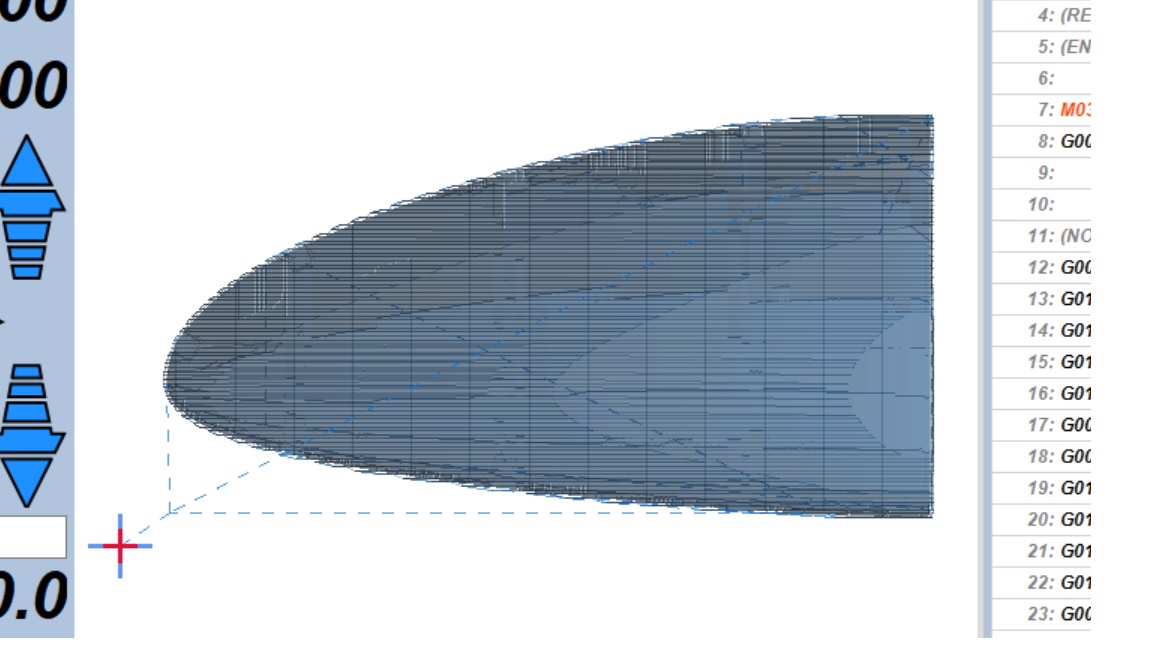
Hi Dan, I have included shots of the previews for both sides and as you can see I am not sure that the origin is in a reliable place compared to the piece. If it was, I would just drill and put a pin in the spoilboard at the origin and by translating the x axis by the correct amount put another at the other end.
I believe Vectric get round this by placing the origin in the centre of the shape and by translating equal distances each side you can put symmetrical pins to flip it on. I don’t think that can work here.
If you are doing 3D Free Machining, in the menu bar you can “Set workpiece zero” and pick a vertex in the mesh. If there are no convenient points you could add something to the model to serve as the origin. I have never used block machining so I don’t know how that works.
I still haven’t done any carving of this type, but it’s on the to-do list, probably a similar project.
So the origin is offset from the corner, but it appears as though it’s the same offset, so the same trick with the registration pins should work. The problem is that you’ll need the pins to keep the same span of material relative to the X axis, but flipped. In order to do that, the carved area will need to be centered on the pins. You’ll need some information from the model, as to what the X dimension is, then you’ll need to set up a job to place the pins in the spoilboard, and to make the registration holes in the foam at the same distance apart. Then you’ll need to Set up the workspace zero so that the work is in the center. Here, I don’t know exactly, but there has to be a provision for it.
Hi,
Don’t know if it will help but I use Fusion 360 and have a similar problem machining guitars. I find I can just move the origin point to the opposite corner when flipped. The G code then just generates negative values for the X axis which seem to work fine on my CNC. Basically just requires a registration pin on each corner of the stock.
I then zero on the bottom left, cut, flip, zero on the bottom right, cut.
Don’t know if estlCAM / your CNC will do this but may be worth a try.
If you use the center of the stock as your origin point (rather than the corner) and put the registration pegs in line with the center, the origin point remains the same when the material is flipped. This allows you to keep your steppers engaged during the flip.
If you have a well calibrated XY fence and enough space, you can flip your stock and rotate it 90 degrees and keep the same origin point. You do have to rotate your stock in Fusion. This works without registration pins, but it depends on well-cut stock and accurate fences, so it might not work if something needs a high degree of precision in the registration between the two sides.
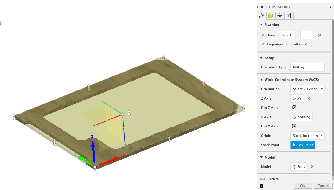
Have you try using WSC on the setup screen of fusion?
You can create 2 setups on for the top and one for the bottom and keep the origen exactly where you want it.
Just need to play with the orientation dropdown menu.
This pictures are just for ilustration as I did not cut the material this way.
That’s what I have been trying to do but I can’t see a way of doing it.
If I use the Free machining option I can set a workpiece zero in the middle but it doesn’t offer a way of producing code for both sides so I can only machine one side. Block machining gives me a Gcode for each side but I can’t see a way of setting the origin in the centre of the piece - unless I have missed something.
Hi Tim, if I understand you correctly this might be the way to go.
So far I have produced the stl in F360 but used EstlCAM to produce the toolpath. I haven’t tried producing the toolpath in F360. I am wondering however, how do you know how far apart to drill the registration holes? Does this come from the size of the stock given by F360? That is the key to the whole thing.
I cannot help you with EstlCAM. I assume you could do it as two separate files, one for each side. I do all my CAD/CAM for 3D objects in Fusion 360.
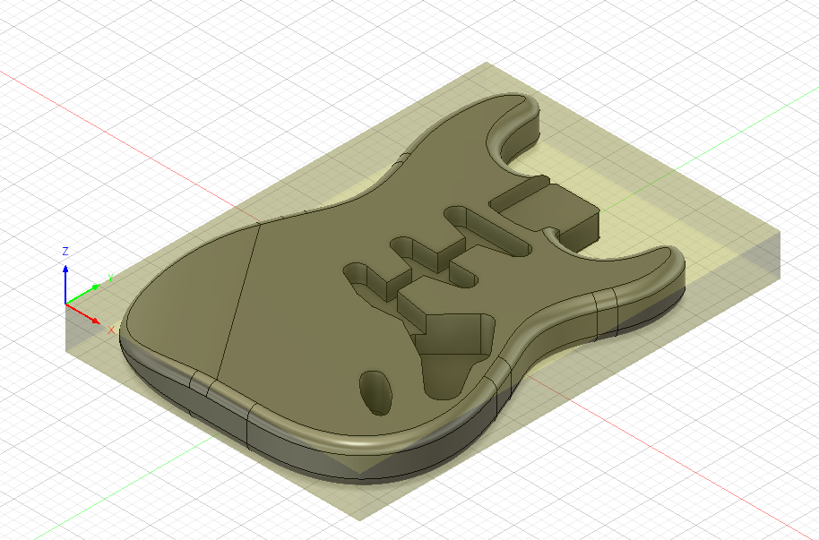
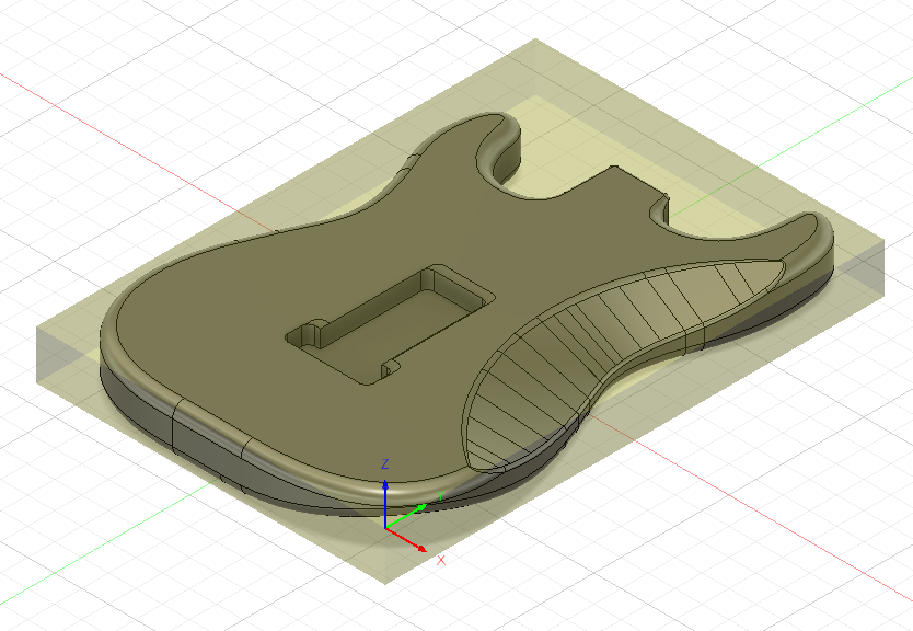
A quick search on Thingiverse yielded this item. In addition to the usual STL file, he included a Fusion 360 file including all the CAM. Overall what he did looks complex, but each of the pieces is relatively simple. I thought studying what this person did for a guitar body might give you a leg up on figure out how to do the CAM for your guitar in Fusion 360.
If you have the model done in fusion, that is half of the battle.
The CAM part can be a little confusing at the biguing but not terible, I also don’t use Estlcam anymore everything Is done with fusion, for me the CAM portion of Fusion is much easyer them Estlcam (once you get the hang of it).
You can change the size of the stock in the setup tab in fusion.
The quick and dirty way to add the registration hole would be adding it to the original design
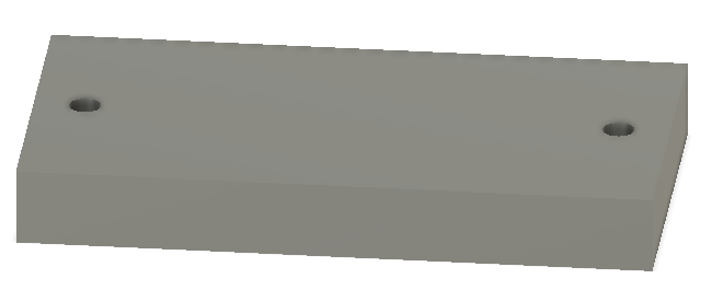
The way I’ve done the registration holes is to create a new drawing and draw circles relative to my finished item where I want to bore holes for the registration pins. Then I go to the Surface tab and do a Surface Extrude to create empty cylinders for the bore holes. In the Manufacturer workspace, these cylinders can be use with a 2D Bore toolpath to define the toolpath to cut these holes. If you are not comfortable using Surface tools, you can create an inner circle the size you want to bore, and then an outer circle a little bigger and create a hollow tube in the Solid workspace.
Note the finished holes need to start at the top of the stock and end in the spoil board. You can either author your cylinders that way, or alternately you can author them the height of your object and then extend the actual boring using the Heights tab of the Bore toolpath by adding to the top and subtracting from the bottom.
In the Fusion 360 file from Thingiverse I reference above, the author took a different approach. He authored a 3D model of the stock as a separate body and included the bore holes in that body. He then 1) used that model as the reference to define the stock size, and 2) used that model to define the bore holes for the reference pins.
Fusion 360 is flexible with multiple difference ways of accomplishing goals, but that can also make it complicated.
I can’t see anyway to generate the toolpaths in EstlCAM but the smart way to go is to do it all in F360 and use the EstlCAM as the machine controller only.
Here is a clip I found that covers a good way to do it that I think I will go with:
Thanks for all your help guys, I appreciate it There is so much to learn in this game!!
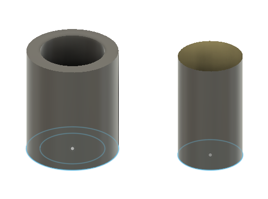
I just watched part of the video. His video did not say, but his “cylinders” are Surface Extruded not Solid Extruded, but you can use a Solid tube to do the same thing. Here is the difference:
Both will work, but they are different things. If you look at the bodies in the Fusion 360 browser, you will see the different icons:
An alternate I mentioned above is to define the entire stock as a separate object and establish this is the CAM stock. This stock is defined around your object in the way you want your object to be positioned within the stock.
This second method can be helpful if you are trying to position the carved object in a certain way, for example, if the wood has some flaws, and you want move the object to avoid them. This moving can be done with the CAM/Setup features without defining a separate model, but sometimes working visually is easier.
Yes. I use the stock as the key. I place the pins at the corners of the stock and zero in on either pin.
I am drilling 4 x 6mm holes and then using the holes to align the 6mm cutting bit I am using. Not super accurate but good enough for a guitar.
Yes I could use this. I was just using a 6mm hole to align the 6mm cutting bit I was using. (not super accurate but good enough). Seemed the simplest way, though probably not the best