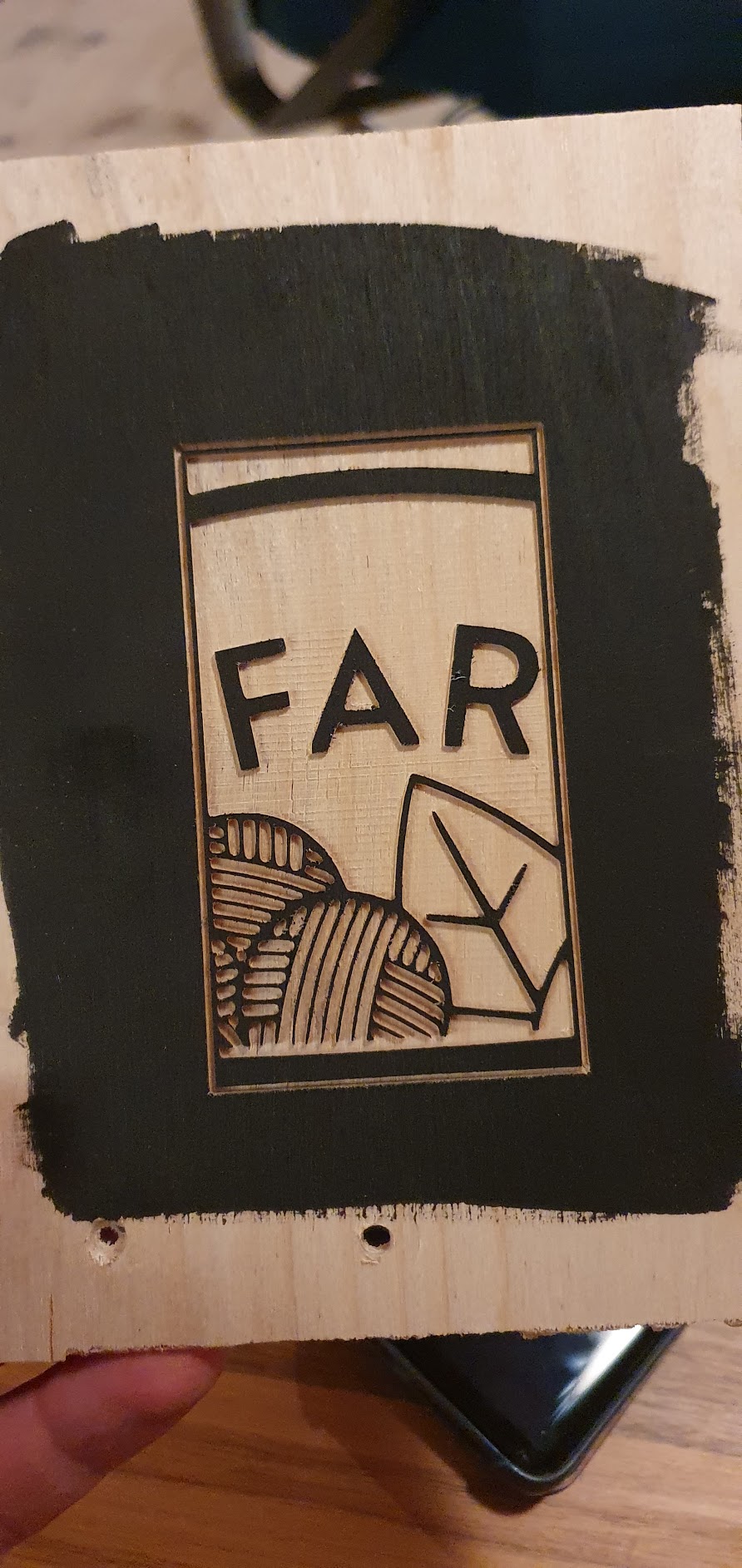
This cut is done with a 0.8mm mill, for the details. So, here comes my issue:
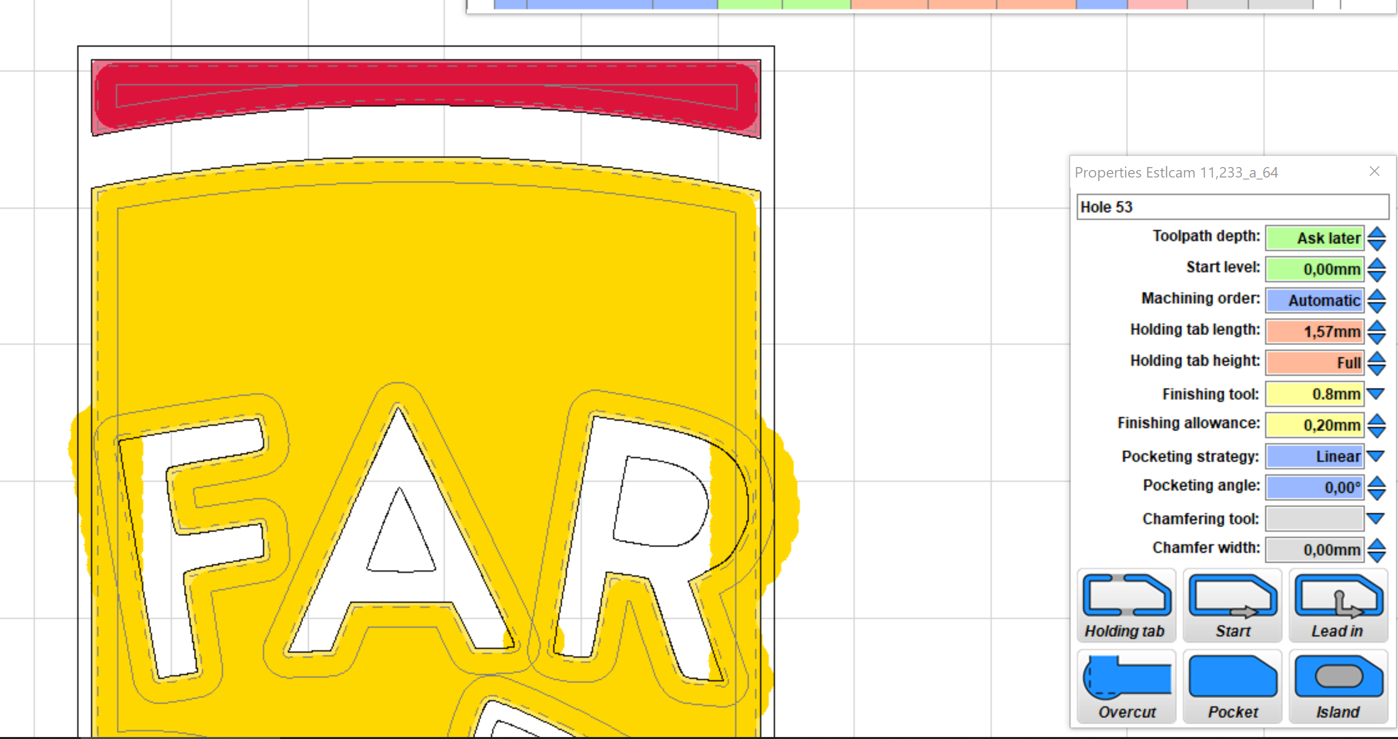
I want to do a tool change during the large job. The 1/8" for the open spaces, and the 0.8mm for the details. But when I try to setup cutting paths with the 1/8" this things happen:
Notice the upper hole, the 1/8" does the main job, and the finishing tool gets the corners. Perfect.
BUT - the hole around the letters (islands/parts) doesn’t take into account that the space is too small for the 1/8". When I play with the finishing tool allowances, nothing changes in the 1/8" path… are there any ways to make estlcam figure this out by itself?
Did you set up the letters as “islands” in the pocket? It appears that it’s just doing the shapes and pocket separately…,
edit: I think that when you machine it, for the xupper hole, you may find that the 1/8" does the main work, and then the 0.8mm bit does the whole pocket again, cutting air where the 1/8" bit has gone before.
Yes I did. You see the shape around the R… don’t understand how I can make the 1/8" avoid the narrow areas. I could draw the paths by hand, but that’ll take a long time!
Take the other part out and just run the simulation in Estlcam, that will show you what it will do.
I see that. Looks like it will collide between the A and the R as well. Since the parts are separate operations, you may have to manually set the paths for this. I think for the tool change, you might need to anyway.
I haven’t tried a tool change for a finishing pass, but I have done tool change milling operations. Another possibility that I see for the finish pass is that it might leave some materials in the corners, doing only a single tool width for the smaller tool, which may not clear the corner. Well, maybe it’s smarter than I think, but I’ve been using manual pathing for complicated things, because it doesn’t seem to figure out what I want automatically.
I thought there was an option for choosing a different roughing tool, where you can pick the 0.8mm for that. Or maybe it is the opposite and you need to use the 1/8" tool and choose the 0.8mm for finishing?
I want to use the 1/8" for roughing, and the 0.8mm for the details. This is how it turns out, with the big mill, and the small mill for finishing pass:
Edit: I realize that I might be too demanding. If I was to do a large job, where some details would need a small mill, I could create sections depending on what mill would suit the job. It wouldn’t take that much time to set up.
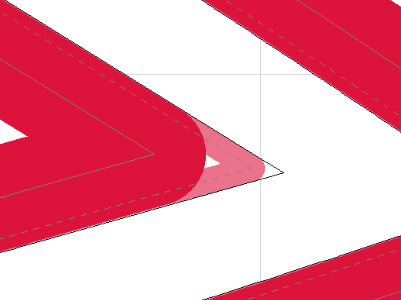
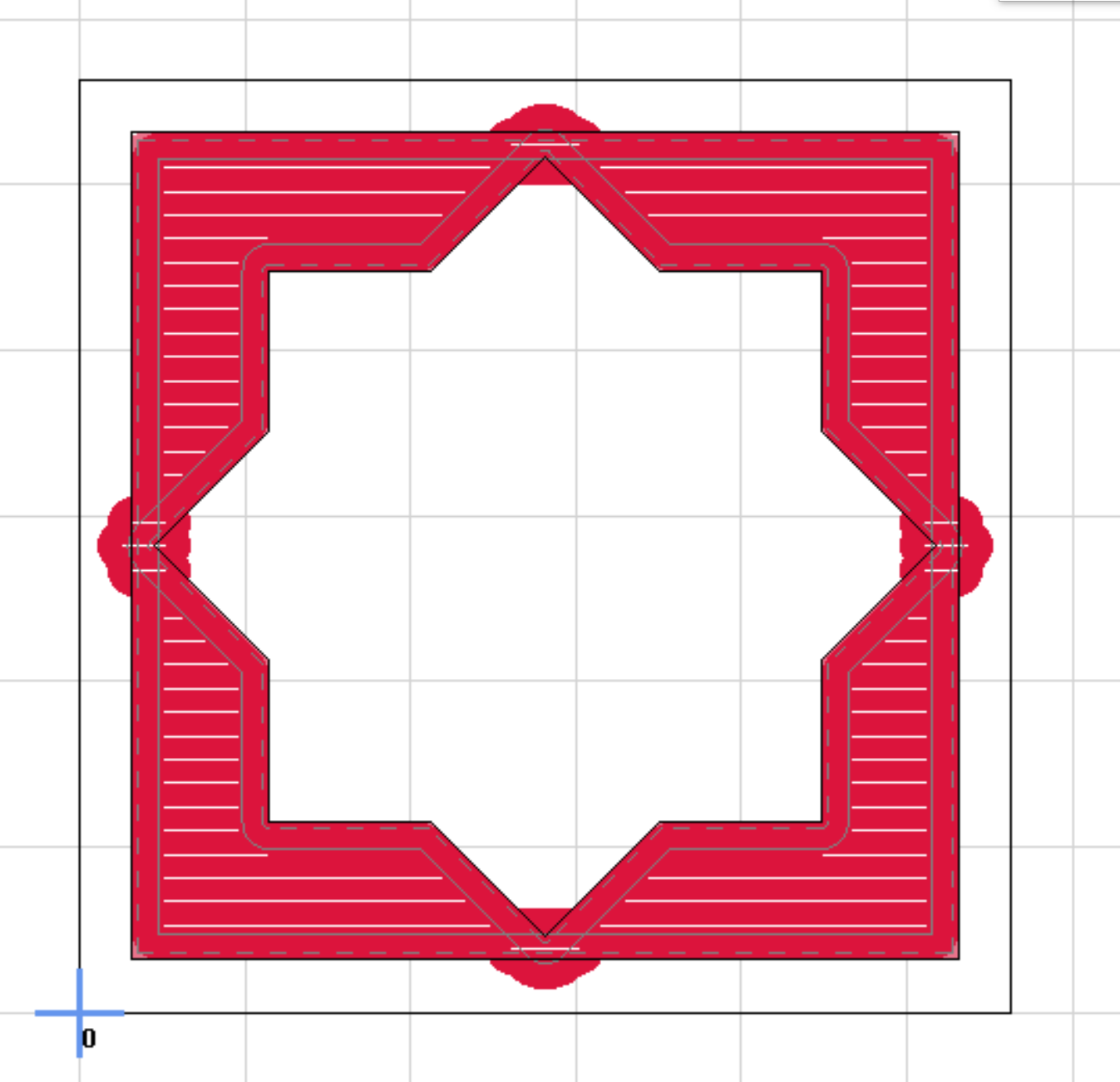
I was playing with this today, and came up with method that seems to work.
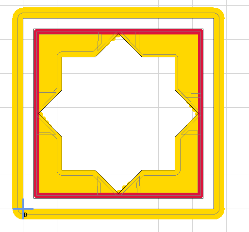
Use the manual path tool for the larger bit, eliminating the areas that are problematic. then again use the manual path tool for the smaller bit, covering only the areas that you left behind with the larger bit. You need a little bit of overlap to cover the area where the larger bit’s diameter has left the path. You can see what that’s like here:
For this, I used the bits that I had defined, a 1/8" and a 1/16" It would be better with a smaller bit, there’s still some hinky stuff in the pocket with this bit.
Using a pointed carving bit is probably a better plan for this kind of thing, but at least there’s an answer.
I just have to write an immideate reply, before looking into your details:
Are you evesdropping on me? Or are you a telepathic mind reader? I made quite precisely the same shape to test tool paths in estlcam! I never got to run it though…
Thanks for the demonstration though! (I’m quite confident that you are NOT evesdropping one me ) I actually ended up with the same approach, just didn’t get to update this topic. I’m going to use the manual tool to precisely define what areas that should be used milled in either way.
How to do a good finishing pass when the sizes of the mills are too much? There are no options to broaden/double the passes. I guess I could cut it away with a small chisel, but that kinda defeats the whole purpose…
Honestly, for that, the piece is likely to break out. But you could do a very small manual pocket, I suppose, same as for the larger areas.
While the CNC is very repeatable, I don’t expect that the tool is going to be the end of the work. There’s always finish work left over when the big tools are done if you work in a shop. there is very often still something that you have to do with the work when it comes out of the machine, just like you have to finish taking out the holding tabs. What matters is that you make it possible to do so in a consistent and repeatable manner.
My lesson learned is that the simplest approach is to make as many custom paths in estlcam as needed. There’s no magic wizard that can process automatically- unfortunately…
 ) I actually ended up with the same approach, just didn’t get to update this topic. I’m going to use the manual tool to precisely define what areas that should be used milled in either way.