Hi,
I am working on my Lowrider… It’s quite finish and working but i have some trouble with the endstop …
I’ve some questions do understand it !
1 - What is the difference between endstop and dual endstop ?
2 - I have endstop for Xmin Xmax ; Ymin Ymax ; Z min x2
3 - What is the latest firmware needed ?
4 - Do you have topics where i cans find the hole explinantion to wired them ? ( I am doing an extra large lowrider so i have to redo the connection of the pre-set wires )
5- How do i have to plug the wires for Z ? ( I have 2 x Zmin to autosquare the machine )
Zmin, and whatever endstop is set in configuration_adv.h
I have to add. On a really big low rider, you don’t need endstops. You can make the machine square before energizing the motor with a tape measure, and because you are squaring a 5 foot long gantry, it is easy to get it very square.
I have a ARCHIM 1.0 … What do you mean by “edit it” ?
I have seen a lot off people doing it and it seems really convenient ? I need them because i will do a repetitve job so i have to make the Lowrider the most automatized as possible
So … When i will have download the latest firmware, what will i have to do to make it work ? I’m sorry but i’m a lit bit lost with that …
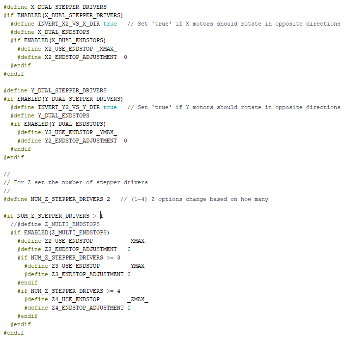
The branch of firmware should be V1CNC_Archim_Dual. That is configured for two X and two Y drivers though. So before you flash it, you’ll need to change the settings in the configuration_adv.h file. You will need to turn off the dual Y drivers and set the number of Z drivers to 2. You can change the file right in arduino before you flash it.
Thanks again …
In my further configuration i will have :
Xmin ; Xmax
Ymin ; Ymax
Zmin(right) ; Zmin (Left)
Wich lead me to 3 questions …
1 - Why turn off the dual Y drivers ? ( I need two ? )
2 - To set the Zmax, i can put the values directly in arduino ? How ; Where ?
3 - How can i turn off / turn on the drivers ? By set “true” or “false” ?
You only have 5 drivers. You have to pick which two axis you want to have separate drivers. There isn’t any difference in current between running two motors off of one driver, or two drivers for two motors. I am also not sure which motors are in your gantry (X or Y).
To disable dual motors for an axis, you just add // to the front of the line so it would change to: // #define Y_DUAL_STEPPER_DRIVERS
Homing to Zmax is another complication. You’re really not making it easy for yourself
The motor on the gantry is the X.
I’ve couple the 2 Y motors. For the moment the 2 Z motors are coupled too but i’m thinking of seperate them to square the lowrider in the future …
My questions are as follow :
1 - How can i configure Arduino with those informations ?
2 - How can i auto-home after ( to make the machine knows its limits ) ? Is it in Arduino or in Reptier Host ?
Marlin doesn’t home to both ends to understand the limits. It is open-loop, so it just does what you tell it to do.
In your situation, you should use single X, Dual Y, Dual Z.
If you want to home Z up, instead of having it rest on the endstops, then you need to change a few things:
Disable X_DUAL_STEPPER_DRIVERS. So that line will look like this: // #define X_DUAL_STEPPER_DRIVERS
The X endstop will be mounted on the left of the machine, and it will be plugged into the Xmin port on the board.
Leave Y alone. Plug Y1 endstop into the Ymin port. Y2 into the Ymax port.
Change the 1 to a 2 on the line that sets the number of Z drivers. It looks like you already have in that screenshot. In Configuration.h, change the Z_HOME_DIR to +1. This is where that is:
The Z1 motor should be plugged into one of the Z port.
The Z2 motor should be plugged into the E1 port.
The Z1 endstop should be plugged into the Zmax port.
The Z2 endstop should be plugged into the Xmax port (that’s not a typo, it is set to use the xmax port).
You may have to adjust the inversion of the endstops. They are defined here:
They look right to me, but when you get the machine flashed and wired up, you can send M119 with Repetier Host and it should respond with a list of endstops, and each one should show TRIGGERED or open. If any of them are backward, you can invert them.
Be careful when you are connecting the endstops to the board to never use the (+) pins. Only (s) and (-). The positive can short to ground, and ruin stuff.
Since you’re making modifications, you might as well set the BED_SIZE. The only time this comes into play is when you “home” it will only travel BED_SIZE before deciding it is an error. So if you leave that at 200mm, you’ll need to be close to the endstops to be able to home.
There are no checks to keep you from going too far to the positive direction. After you home, it will not let you go negative, but it won’t look at the endstops except when homing.
Before homing, make sure that M119 is showing the right thing (triggered when you click the endstops, open when you don’t). Also, make sure your manual movement commands from repetier go the right way. Positive Z is up, Positive X is to the right, positive Y is away from you. Just like in your photo.
Once you have everything flashed, and you have M119 showing the right thing, you can home an axis using G28. G28 X will home just the X, G28 Y just the Y, etc. `G28 should home X, then Y, then Z. But I would test each direction independently first, and have my finger on the power strip switch in case it doesn’t work for some reason.
Thanks for your answer … And escuse me for the delay i answered it back … I burnt my Archim 1.0 so i have to buy a new one … I choose the Rambo 1.4 …
I have all wired again … And i’m now really near to the point. My Endstop are pretty working.
But it resut again two problems …
1- My enstop X and Y are working but ther is a delay of 66 second before the lowrider stop and the moment it go on the opposit direction for few millimetter. I have cheked all the file in Arduino but i don’t find anything here. What could be the problem ?
2- I cant do the autosquarring because the machine just consider the first enstop. I have wirred the 2 Z stepper in parrallel. When i tried to do put “2” in the line that sets the number of Z drivers, i have an error message saying : "error “If NUM_Z_STEPPER_DRIVERS is 2, you must define stepper pins for Z2.”
Start with the V1CNC_Rambo_Dual branch. Disable dual X and set the number of Z to 2. That should compile. If it doesn’t, show me the log, from the top.
Then before running homing, send an M119 to check that:
You have Z2 and Y2 endstops.
The right endstop is triggered at the right time for each motor.
Thanks for the answer …
So I disable X and the delay dissapered so i do the same for the Y, i disable it too … It work Great …
Thanks again.
The first question is answered ( the delay)
But the second one, to autosquarre the lowrider is not working … Therer is just one of the Z endstop which are working …
 !
!