Wait it looks like you have it correct. Try adding a 0.2 ± on those tubes, somewhere that fails.
The bearings are 7mm wide but the edges have ~.5mm radius as well.
Wait it looks like you have it correct. Try adding a 0.2 ± on those tubes, somewhere that fails.
The bearings are 7mm wide but the edges have ~.5mm radius as well.
I just threw the drawing together to see “how far off-center would the contact point be” to see if the idea was feasible.
If I understood you correctly, here are sketches with +.2, 0, -.2 variations of the 23.5 and 25.4 versions
23.3-25.6, but that looks good. You are right I double checked, Not sure why I didn’t think it worked. I have a printed part I know it fits, the rails are super close to the edges.
This shows that with 2 points fixed we only have about a 2-3mm diameter tolerance, and have to having a moving third…That could make for a more simple LR set of parts (with more assembly work) but doesn’t work on the MPCNC because of the center.
It’s about time you give up on that MPCNC anyway.
#LowRider4Ever
Not gunna happen
Not till he finishes this one MPCNC. Then lowrider I have a room in the basement for a full sheet machine so please hurry @vicious1
Just throwing this out there because I love algebra  : the angle between the bearings determines how much the position on the bearing changes in response to the diameter of the tube. Larger angles produce a larger difference in position and smaller angles produce a smaller difference in position, for a given change in tube diameter.
Specifically for an angle α, and a change in diameter of Δd, the change in position Δp is
Δp = tan(α/2)*Δd/2
In particular when α is 90 degrees, Δp = tan(45)*Δd/2 = Δd/2
And when α is 120 degrees, Δp = tan(60)*Δd/2 = Δd * 0.866
So for Gene’s diagram, a range of 23.5 to 25.4 would shift the position by only 1.9 mm * 0.866 or about 1.64 mm.
If we allow a 6mm range of position on the bearings then the difference between the max and min diameter would be about 6 / 0.866 = 6.93 mm of range in diameter, which could cover about 23.5 to 30mm diameter at the extremes. All the other tolerances could eat some of that range but anyway that’s what the math predicts.
You math geeks make my brain numb or maybe it’s the Jack but that looks like it will work and does the edge bevel make a difference or will the they stay because you only have 7mm not8 to work in? Now I see the end and 6.93
1” EMT. YAY. I’m in.
Here’s a thought for making one adjustable bearing. It’s very similar to the standard design, except the hole for the axle is elongated into a short vertical slot, and two bolts threaded into the plastic push down on the axle to hold the bearing against the tube.
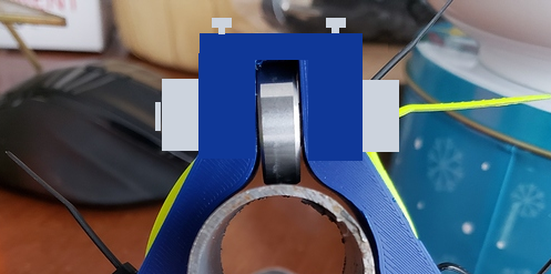
The gray blocks on the sides are supposed to be an M8 nut and bolt, the two smaller T-shaped blocks on the top are the heads of two vertical M4 bolts.
Wow, this really took off! I love the ideas, and it’s definitely a huge upgrade on my original notion.
Boiling down the past few posts, I see two directions emerging. One is to do it as @jamiek suggests, where the bearing block is printed in two sections, with a sliding member. The other is as @RobinBennett suggests, with two adjustment screws.
I have some thoughts on which way I’d like to go, but I’m going to think a little longer before diving in.
One thing to consider with both strategies is that the Y-plate doesn’t lend itself to these kind of 1-D adjustments.
Notice that individual bearings don’t line up vertically. This means that we couldn’t fix two and leave a third mobile. Lining up bearings would require redesigning the plate and bearing holders. This isn’t necessarily a bad thing, but it could be if there’s a reason why the original design has contact with the tube every 60 degrees.
It’s also getting toward a larger redesign and it might make sense first to get input from @vicious1 about lessons learned during y-plate design and testing.
Measuring with calipers on the bearing set from the kit, I get .75mm fillet radius, i.e. 5.5mm of usable flat width.
Great closed-form analysis. I think that we can grow the envelope a little by allowing the bearing to be positionable along the axis. Basically, make the notch wide enough that there’s a 3-4mm gap, and then use some washers to position the bearing so that the center of the bearing is somewhat close to the contact point with the tube.
This doesn’t need to be precise, and washers of this kind can be made out of any convenient material. For coarse work, some convenient thin plywood works. For fine work, I would just use a pair of scissors on some old plastic packaging.
The upshot is that we go from ~7mm of range in diameter, to ~10mm. That’s the difference between 3/4EMT (23.4mm ±.2) and 1.25" (31.75mm ±.2). Therefore, a 3mm gap-- quite small all things considered-- allows for the entire range of likely tubes, including some wiggle-room for tube and bearing tolerances.
Sliding along that axis is also not a control variable, so it’s not something we have to tune or which could get out of alignment with other parts in the system. Whew.
FWIW, I think that there’s an argument to be made for optimizing bearing loading directions. It’s unclear to me if the tube is driving the plate downward, or keeping it from falling. This depends a lot on the cutting loads. However, when I think of a drill, it’s definitely the case that I have to push down on it, its self load is insufficient to drive it into the material. However, if I’m using a hand-held router, even a palm one, there’s no need to push. So I’m kind of at a loss here.
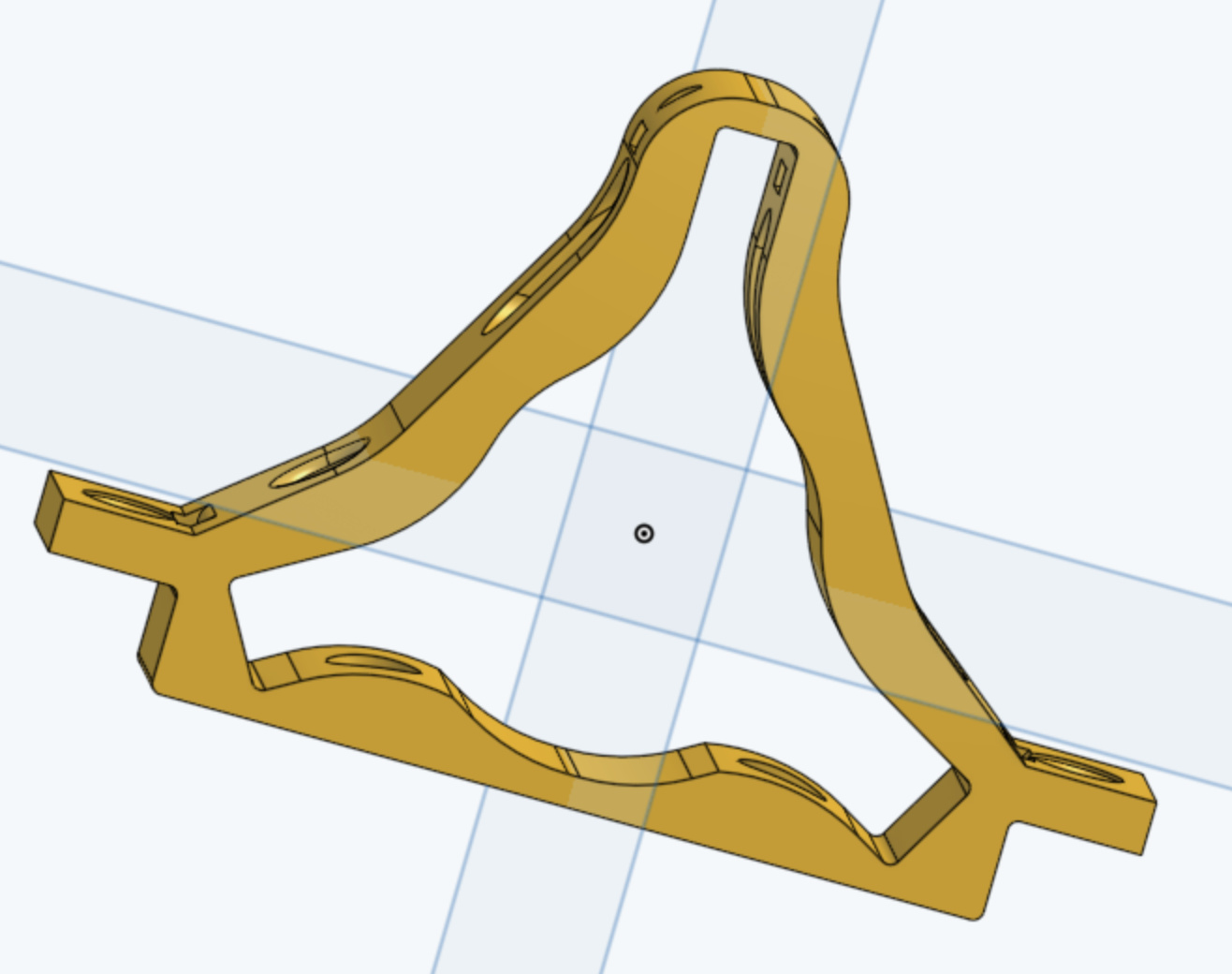
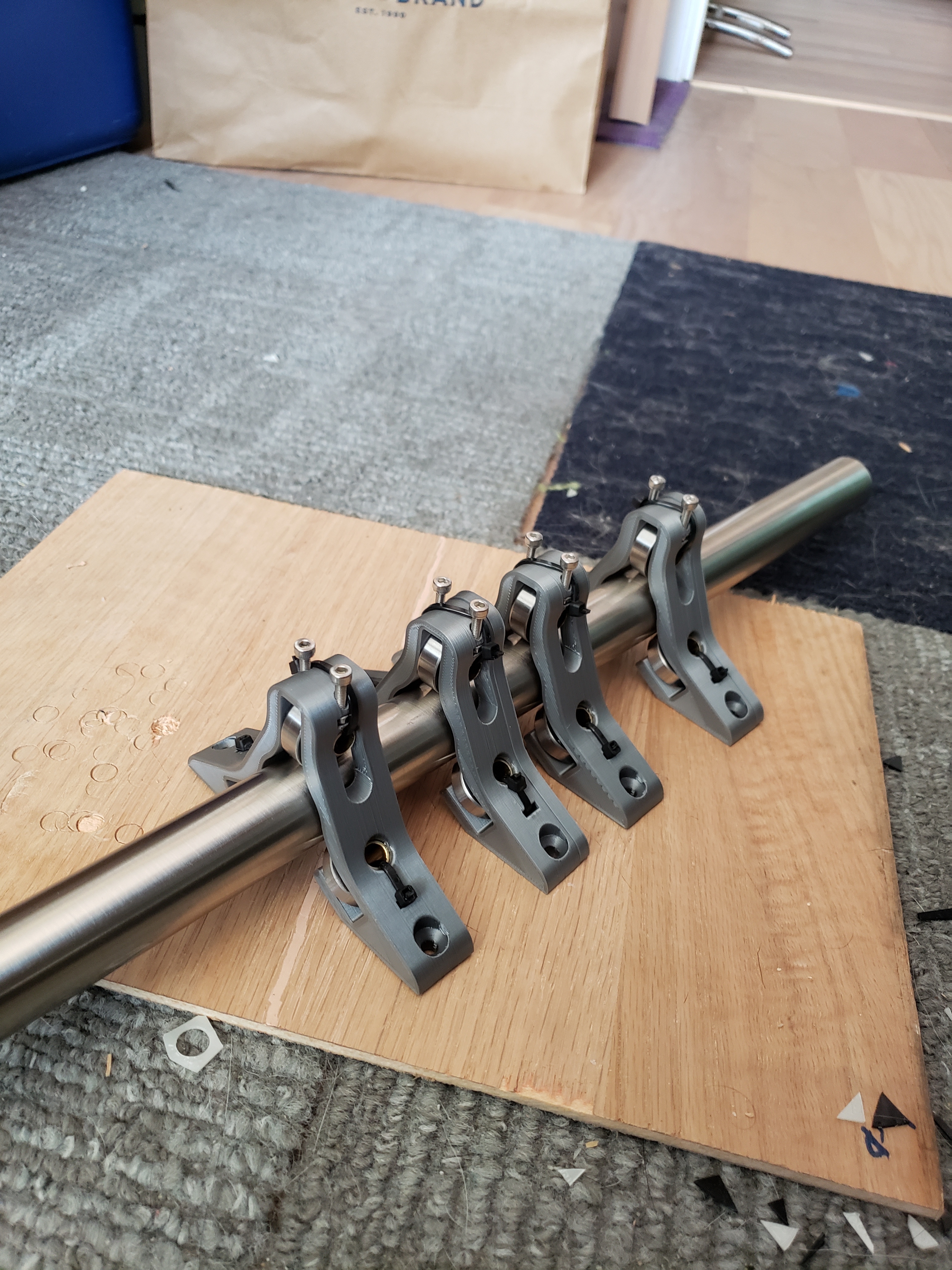
I gave a stab to the adjustable bearing approach. I realized that this block could be used for all 12 locations, which would simplify the build and prints.
This uses hollow brass tubes as axles (we couldn’t use a bolt as an axle because the bearing will wobble on the thread), and thus retains the zip-tie features. However, the zip ties no longer carry any load, they simply keep parts from falling out.
The two adjustment screw holes can be seen at the top, as well as slots for captive nuts. The holes are sized for M3 (SAE #4 will work if standardized hardware isn’t available).
Also note the 3mm extra width in the notch around the fixed-axis axles. This provides for the longitudinal sliding adjustment required to handle from 3/4" EMT to 1.25" plain tube.
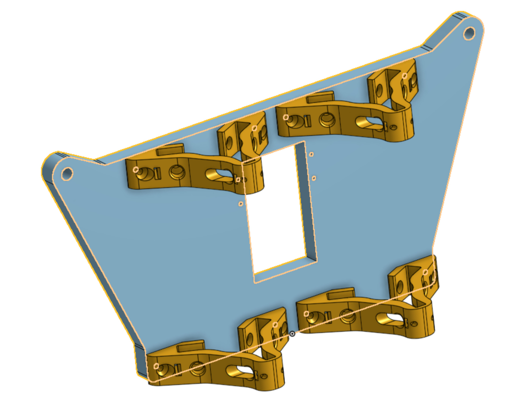
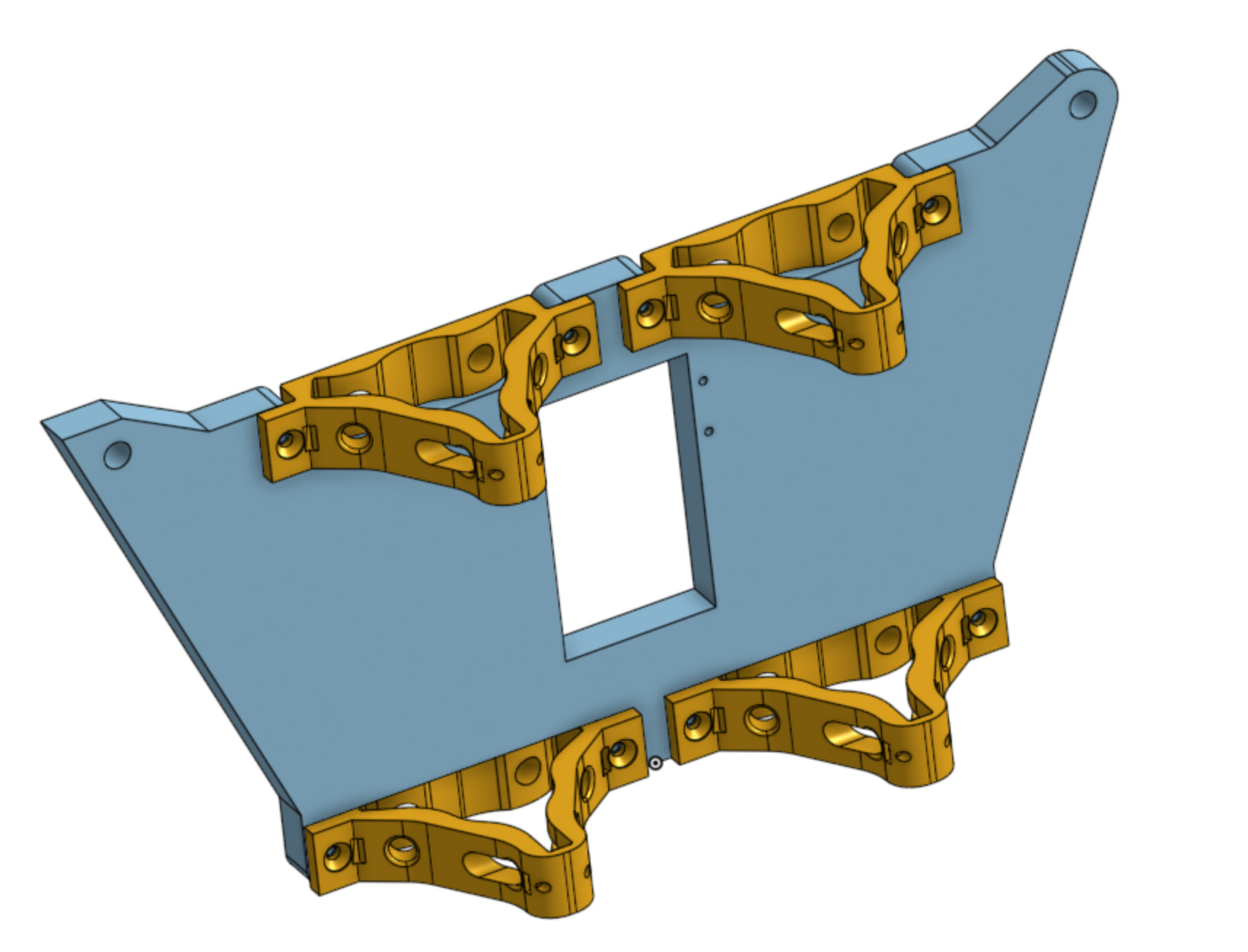
Using these bearing blocks for the Y-plate looks something like this:
It does require splitting the wheel arm from the bearing block. I feel that this is only a problem if it introduces flex in the structure, but I believe any flex can be engineered away.
Of course, the lateral block location can be adjusted. And if additional plate mass is a problem, it can also be significantly lightened by carving out some holes. However, the plate raw material dimensions don’t change, as the enclosing rectangle is identical.
However, the distance of the tube from the plate grows by ~3mm and this can’t be reduced anymore without wall thicknesses getting very small. I don’t know if this increased distance is a problem or not.
Maybe worse, this moves parts of the bearing block past the rubber wheels. That means it cuts marginally into the working area.
Thoughts?
I take that back, if we cut notches out of the y-plate, the brackets can be mounted on the inverted side, bringing the z tubes much, much closer to the plate.
The downside is that we have now introduced new unique parts (unless we modify the spindle plate in the same way).
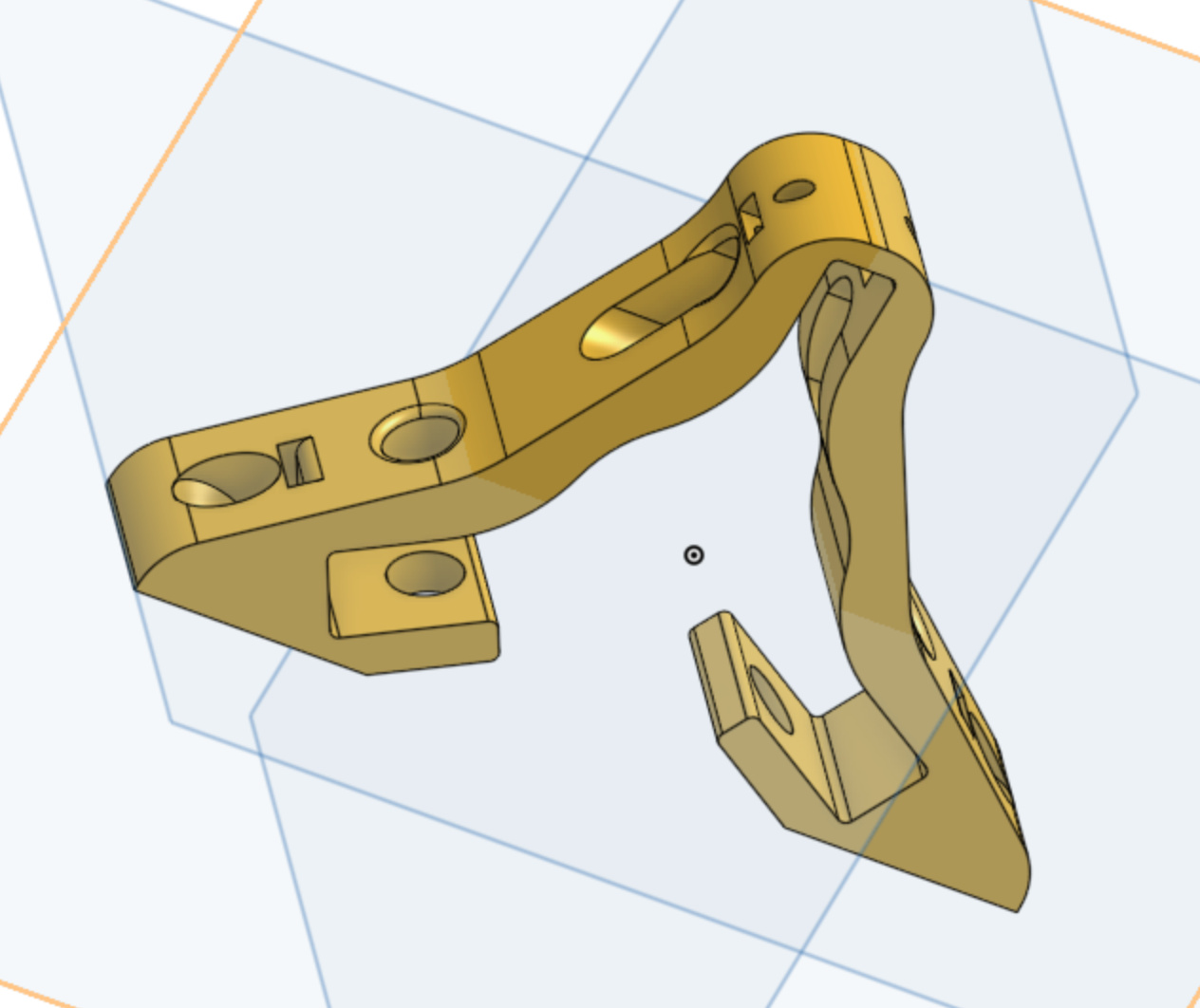
Here’s the proposed piece. This moves the Z-tube as close as 1mm from the y-plate, but the mounting tabs can be shifted backwards so that the Z-tube will have more clearance. Is that desirable, though?
Here’s how the modified assembly looks:
I would recommend modifying that part to reference off the inside face of the plate rather than the outside.
All the current LR2 parts that attatch to the Y plate reference on the inside face. This eliminates any reliance on or limitation to the thickness of the Y plate.
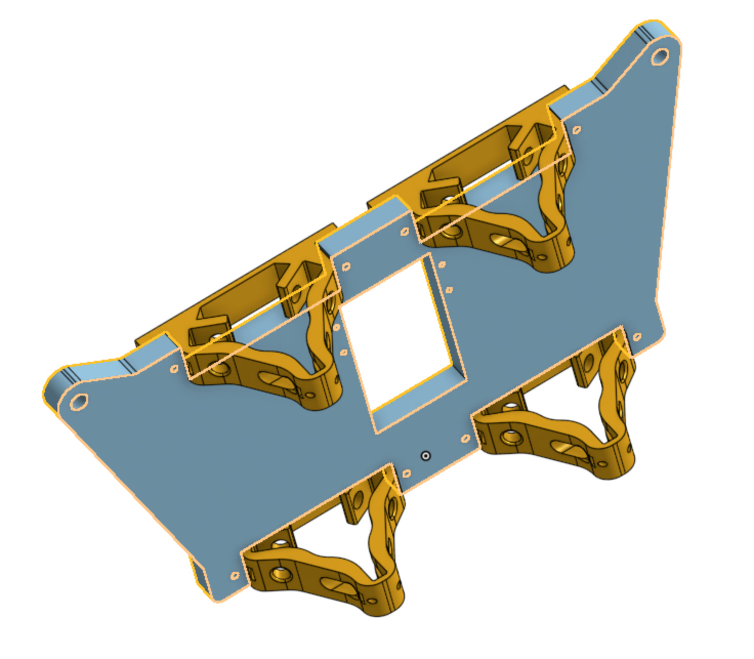
Great point. Here are updated models which reference to the front side of the Y-plate:
This seems like a doubly valuable upgrade. With the tabs in the new location, the same part can be used on the spindle platform, bringing the X-tubes 1cm closer to the plate.
P.S. Note to self, the Z tubes need to have some clearance for the belt to pass behind them. This might be substantial to the point of eliminating all the gains.
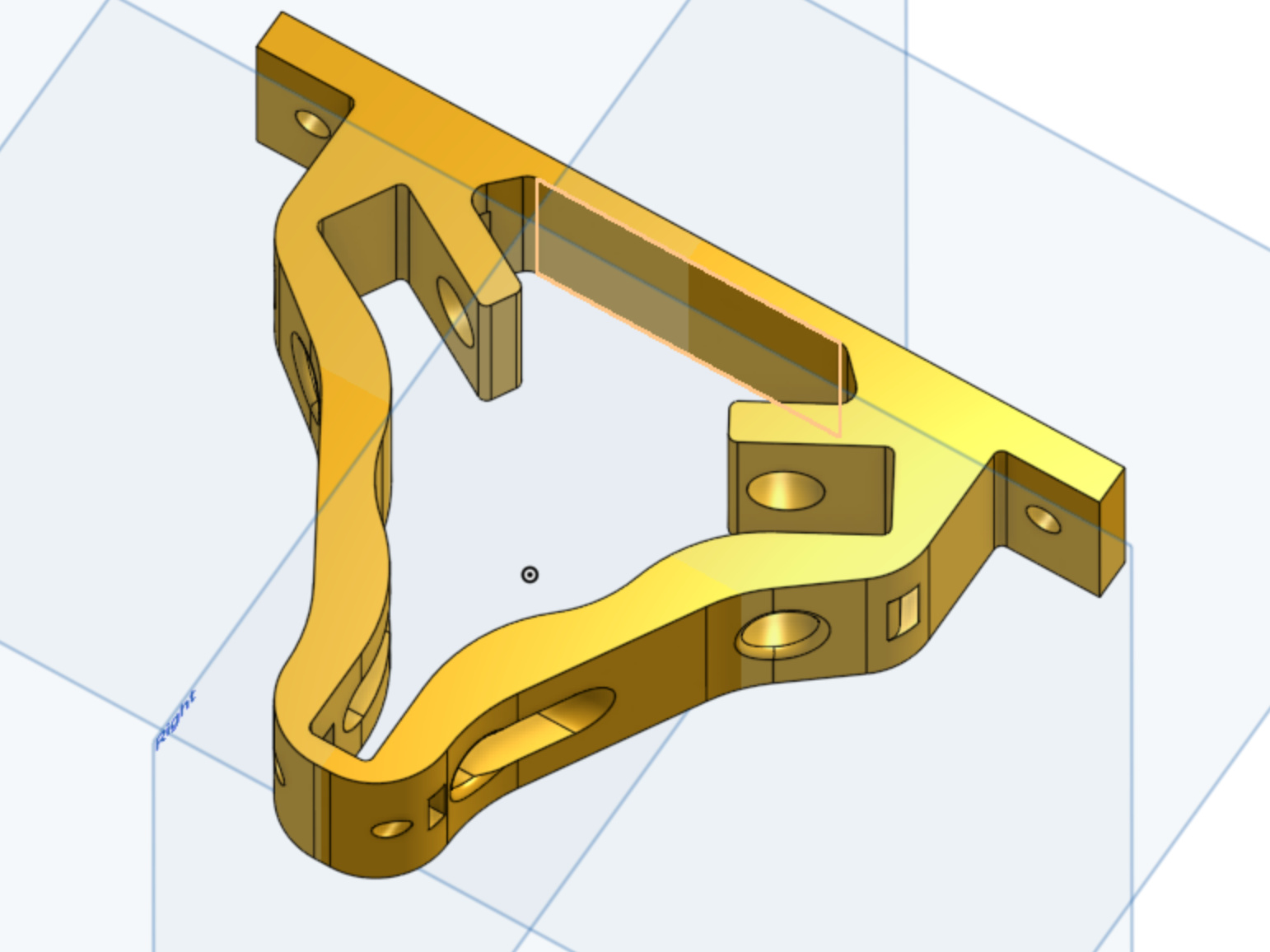
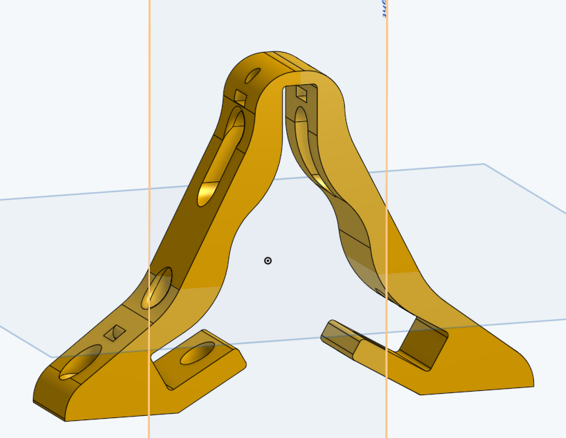
Final version:
Note that I got rid of the recess. That was because ultimately the distance of the tube from the plate is driven by the need to allow clearance for the Y belt. It would take a further redesign to get this sorted out, and it’s likely a major change since it involves new belt geometries, and not just an optimized block.
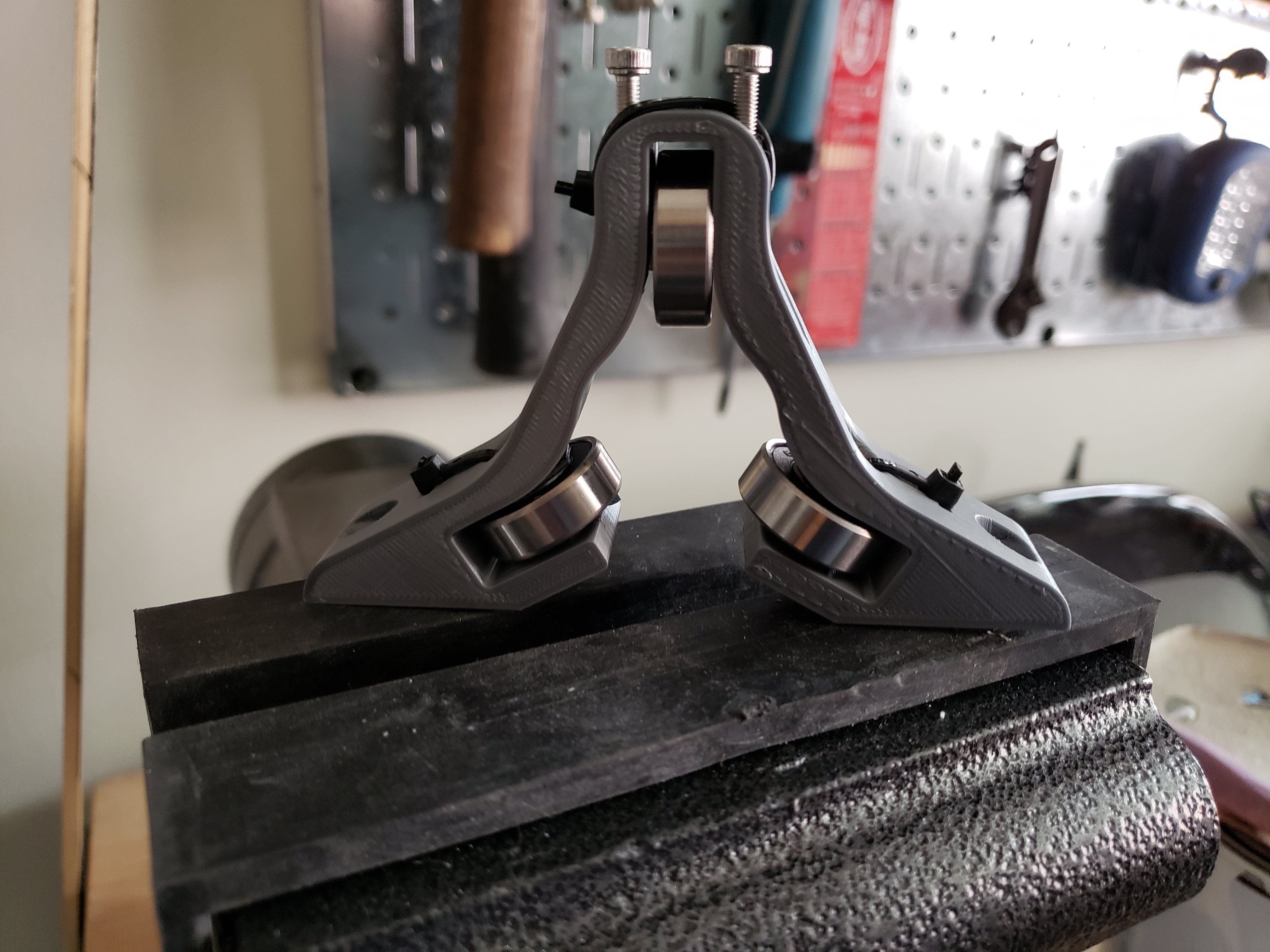
Note in the assembly how the bearings are retained by zip ties, but the zip ties are non-load bearing. The two screws at the top adjust the pressure on the rail, and from my tests I can build an unreasonable amount of force.
Smooth like silk!
It comes in two variants, a 1/2EMT to a little larger than 1", and a little smaller than 1" to 1.25". The reason there’s some overlap is so that one size bearing block can do an entire assembly. If it’s for a small lowrider, then 1/2 EMT for the Z and 3/4 EMT for the X. And if it’s for a large lowrider, then 3/4 EMT for the Z and 1" for the X. And if it’s for a large, stiff build, then 1 EMT for the Z and 1.25", for the X.
Getting close to assembling this thing!
Hi Kenn,
Good idea. I have been dicking around with material sizing and like the idea of a modular system. Given a typical 0.065in wall 1" vs the same 1.25" is half the deflection (1.25" stainless with a 1500mm span yeilds 0.5mm deflection with a 6kg midspan weight, and 1" is 1mm).
For the purpose of accuracy do you think it would be easier to have captured bearing axles at all 3 locations with the addition of your tensioner idea. If the model was parametric, then you could easily produce tube sizes ever mm from 25-32 and use the tensioner to pick up the slack. Also the tensioner would add a preload capability to snug things up.
I suppose another item would be, can the lowrider be calibrated with a software mesh compensation at midspan?
Also, all bearings should be fixed with bolts. Vertical loads are dead weight taken up by the top, lower side bearings take up the cutting forces for y cuts and z cut plunging
Do you mean a tensioner at each of the three bearings? The problem with that approach is that there is no longer a dependable reference point for the tube. This would make alignment very challenging (albeit not impossible).
But I’m not completely sure I understand your question, so lemme know if I got it wrong.
Yes, in theory, but in practice it might take some iterative learning of some kind. Recall that that compensation would be variable based on the forces in that particular cut pass. So for a coarse cut the forces are higher and thus the
Worse, all this is dependent on the cutting tool, the work material, the feed rate, the spindle rate, etc…
It’s definitely deterministic, but I don’t know how to determine it with any precision. It might take some very sensitive instruments and at that point stiffening the structure is probably the far lower effort solution.
Would make for a fun hobby project, though!
In my design, all bearings are captured in place by the plastic. The axles have a little play in the axial direction, but that’s orthogonal to the bearings and shouldn’t have any impact. What do you see as the advantage of adding a bolt to hold the axle in place?
The downside I was looking to solve was that bolts add inertia, and inertia causes slop because the stepper-motor dynamic model assumes instantaneous acceleration/deceleration. The more inertia we add the less accurate this simplified model is.
I suppose I was rambling. From your photos it appeared that a zip tie was all that held the bearings against the tube. Your model shows bolt locations but maybe the bearings are more a fixed with a zip tie than I suspect.
I figured if the bottom 2 bearings were fixed bolted and the top was bolted with your tensioner you could have a quick parametric design for each mm diameter tube. The range between each mm (or half mm) could be taken up with the top bearing tensioner.
On the mesh I was over simplifying the 3D mesh to simply account for dead weight and sag from the router sitting mid span. Not to deal with the effects of cutting.
Lastly, is carriage weight a big deal for wood cutting? I assume the feeds are 10-20mm/s with low acceleration to limit strain in the router. Sorry I have a lot of assumptions, I’m building my first cutting cnc (second cnc) and only have previous hobby experience with manual lathe/machining world. So take any of my comments with a grain of salt.