Adjustable bearing block (from 1/2" EMT to 1.25" plain tube)

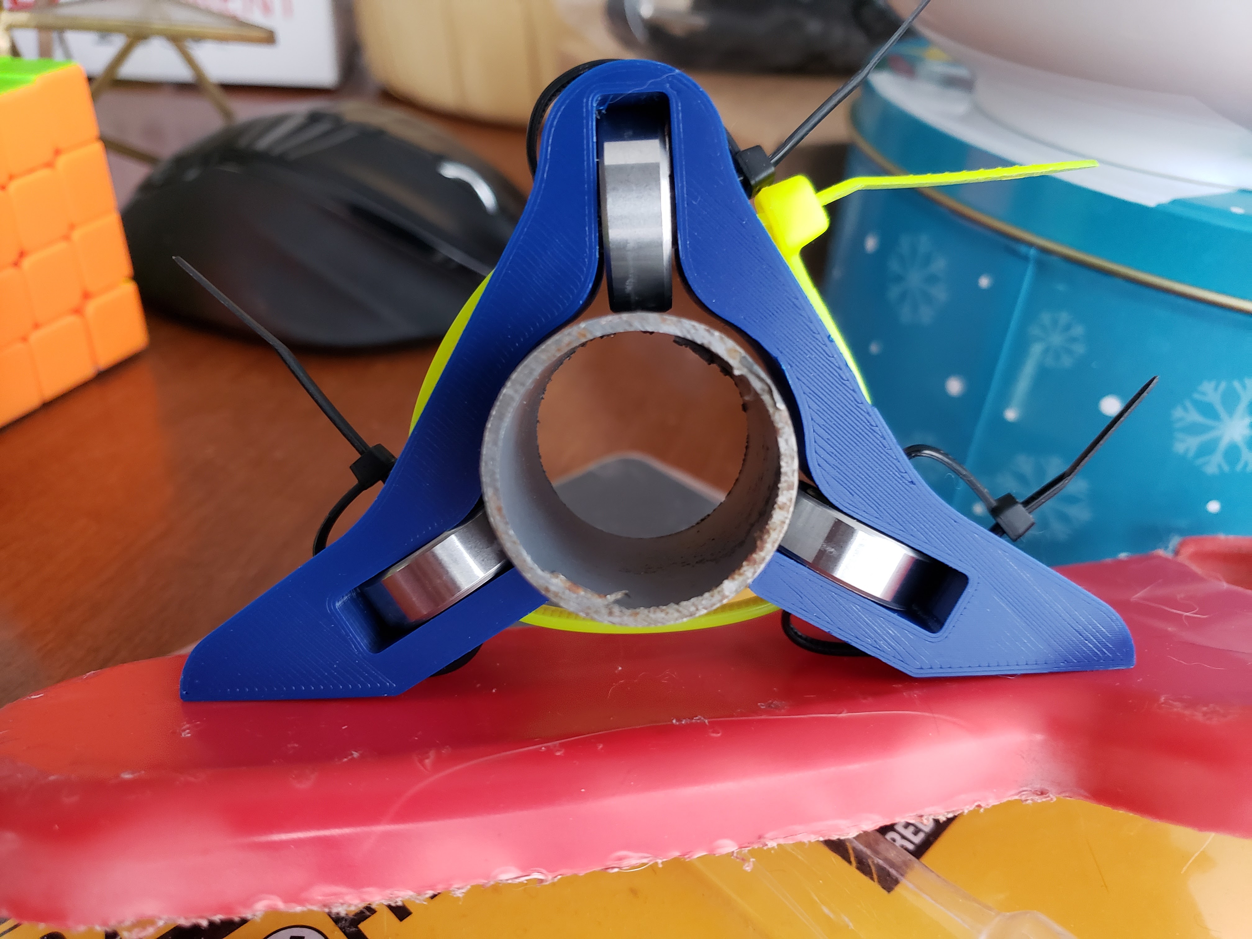
I have made an adjustable bearing block:

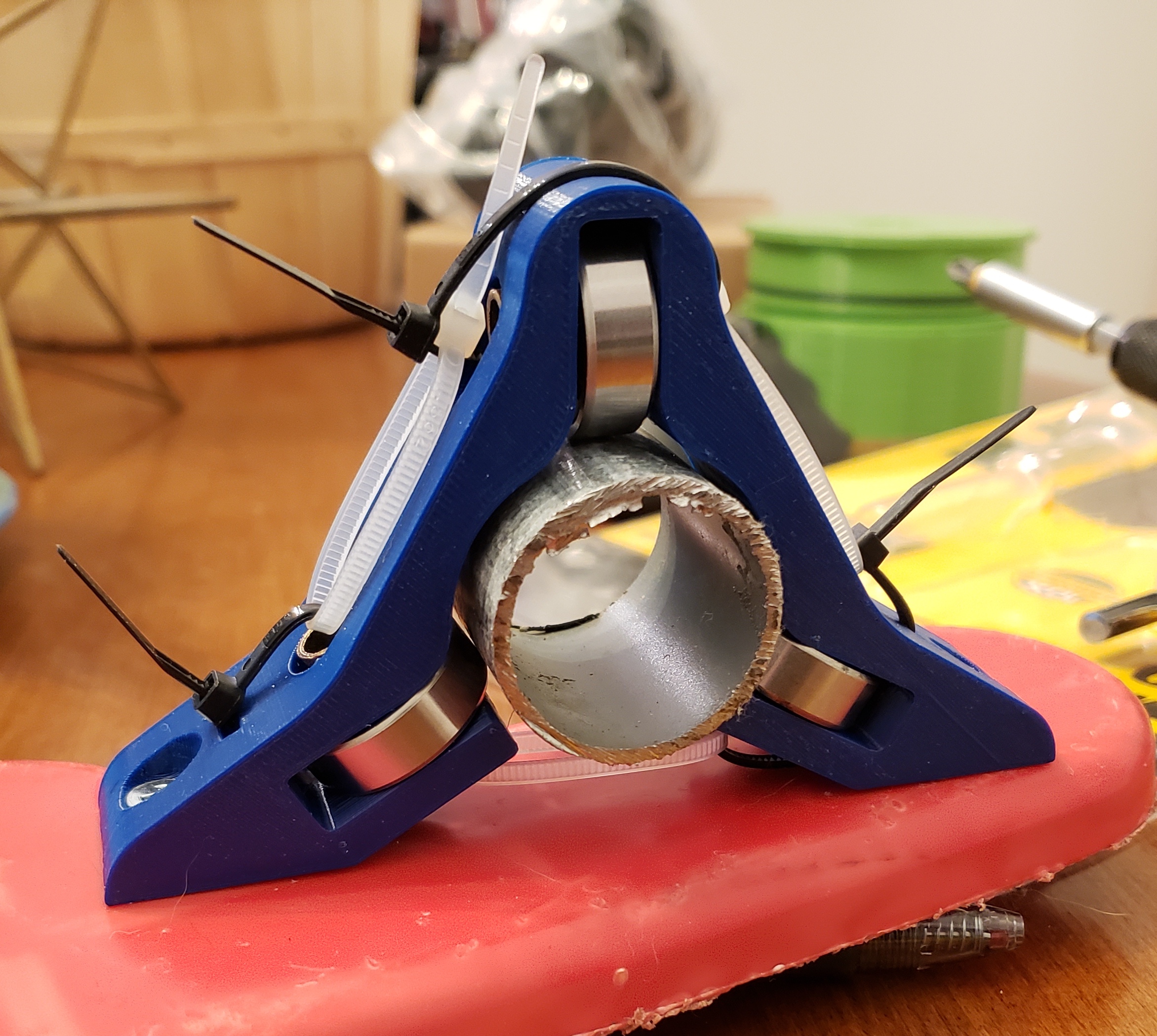
For the picture I used a small section of 1" EMT (1.163" OD), and am very pleased with the result. The block is designed to use from 3/4" EMT (.922" OD) to 1.25" standard tube.

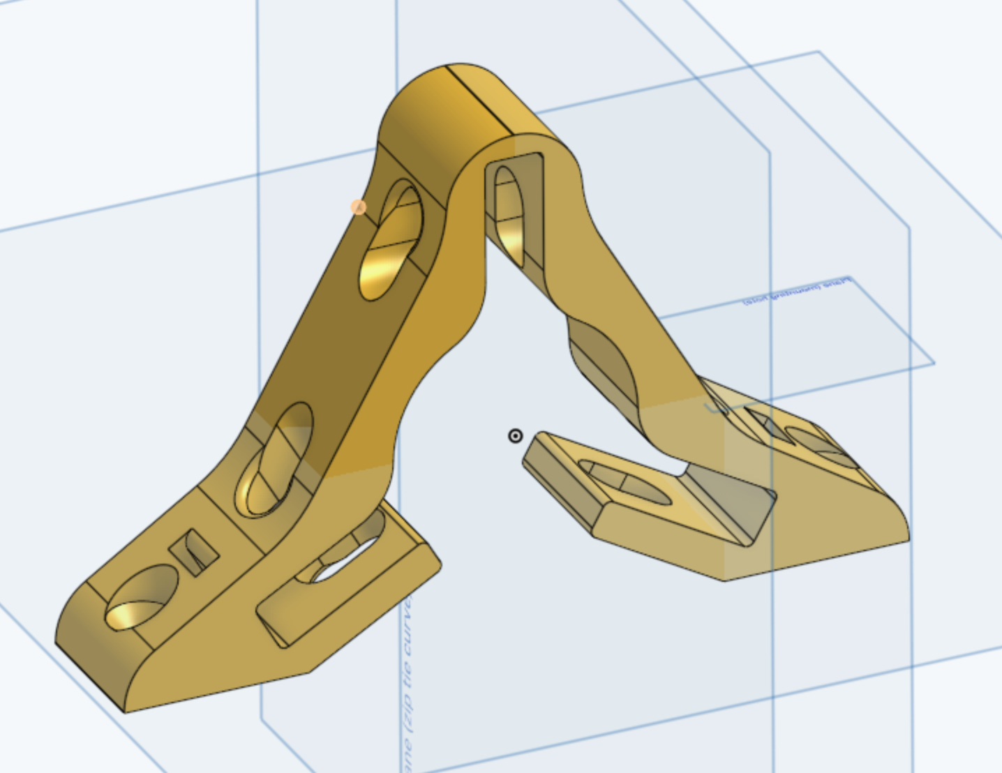
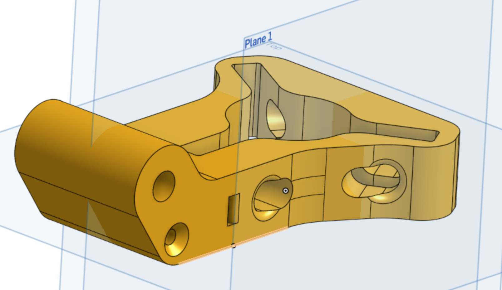
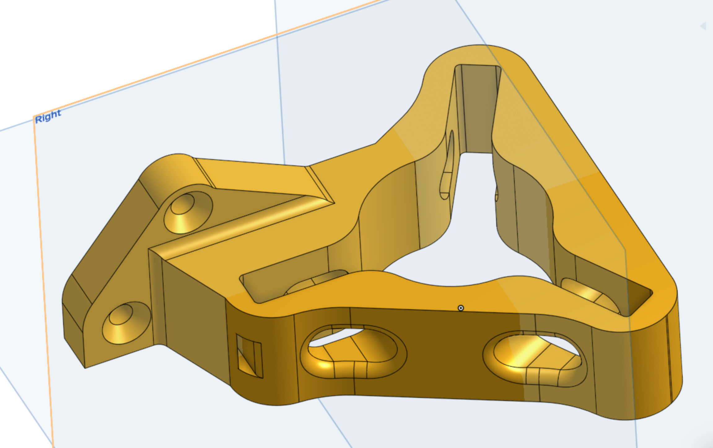
The following screenshot shows the adjustment slots a little more clearly:

Bearing axle

The axle is just 5/16" brass tubing. Any other metal (aluminum/copper/steel) would work just as well. I think that even a plastic might work. The essential bit is that it’s hollow, so you can pass the zip tie through the center.

I don’t have my kitchen scales with me, so I can’t compare weight, but it’s three 5/16" nuts and bolts lighter. That’s a significant difference, esp. if multiplied by the 8 bearing blocks throughout.

Adjusting the size

The zip-ties are the adjustment mechanism. By tightening the black zip ties, the axle moves back, enlarging the hole. By tightening the white zip ties, the axle moves forward, narrowing the hole.

What I like about zip-ties:

  • Cheap
  • Readily available
  • Lightweight
  • Easy to precisely tighten (listen to the number of clicks)

What I don’t like about zip-ties:

  • Difficult to ensure uniformity (placement of the zip-tie head matters a lot for overall tension)
  • Stretchy plastic in a critical dimensional tolerance pathway
  • Impossible to loosen.

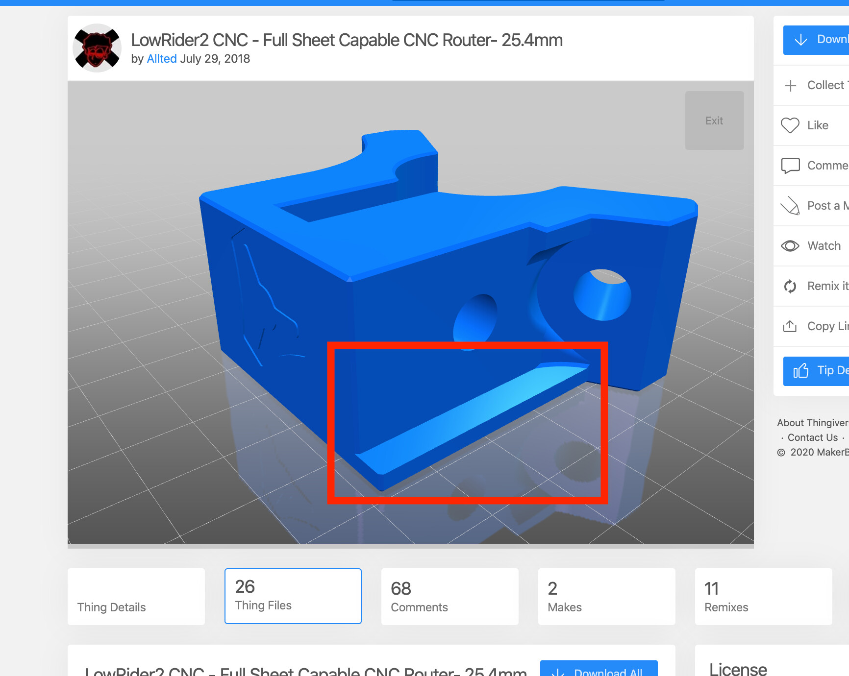
It’s not clear yet if the zip tie approach is the best. However, I believe that sufficiently tightened there will be less deflection than the original design, which has a cantilevered axle.

  • If zip ties don’t work, it could also be done with seizing wire. Just as cheap, and absolutely impossible to stretch with cutting loads. However, it’s fiddlier to apply and adjust.
  • Instead of using zip ties to support the tubes against outward forces, shims could be placed in the slot. The disadvantage of shims is that the provide less adjustability, but that’s arguably not that much of an issue since the blocks should never need to be adjusted once the tubing is purchased.

CAD model

Here is the OnShape file if you’d like to print one or otherwise play around.

https://cad.onshape.com/documents/9bfd836abff9fc3b04fc7b23/w/8b821b524858853269344a9f/e/1469d7f18088eae7bddf721f

Thoughts?

2 Likes

This is creative but I must admit am skeptical of the zip ties. One of the things I realized when thinking through the belt tension and stiffness is that there is a difference between tightness and stiffness and you have to be careful not to mistake one for the other. An extreme example is a belt loop with idlers on both ends, which can be extremely tight (high tension) but not at all stiff. Plucking a note is not a good way to estimate stiffness; you have to look at how the ends are anchored.

On this design if I trace the forces I think I am finding a long and indirect path for the force to transmit from the bearing to ground. If I press up on the tube, the force goes through the bearing on top and attempts to lift the black zip tie at the top. The lifting of the black zip tie is prevented by the two white zip ties on the two sides. Those in turn are prevented from lifting up by the two black zip ties on the bottom left and right, and those cannot lift up because they are wrapped around the blue plastic.

The cantilevered axle might seem weak but the moment arm is pretty short and the bolt is not going to deflect from the shear force. If we assume the hole is oversize (slightly) compared to the bolt then it could tilt a bit in its hole, but that would require the head slipping against the opposite side. It has nowhere to go and the path is pretty direct from the tube to the axle to the anchor.

For a zip tie based adjustment I might feel more comfortable if there were a 3D printed axle with a hook on each end, and hook features on the triangular bracket that allowed tying the axle directly to the bracket with one zip tie on each end. This way the force would be supported more directly (as long as the axle doesn’t break) and there is a shorter chain of plastic conveying the tension. I have also seen modifications where adjustment is accomplished using a screw and nut pushing on the axle from the outside.

I like seeing the creative process and I think the goal of larger any-size rails is very interesting. I hope you will keep it up and keep sharing!

edit: Here’s the adjustable MPCNC with screws pushing on the bolt. https://forum.v1e.com/t/mpcnc-perpendicularity/13937/13 This is intended for squareness, not for alternative tube sizes, although I don’t see why it couldn’t be used to accommodate alternative sizes.

Thanks a lot for your thoughts, you make some great points. In particular, I share your skepticism about zip ties. But they’re soooo cheap and soooo light and soooo easy to use I hate to pass up the design without spending a bit of time exploring it.

I agree with your concern about the force path. We have 6 degrees of freedom and only three controlled variables. This isn’t great for easy calibration. However, because we can consider that we must adjust all groups of zip-ties simultaneously then we can reduce the number of DoF to just 2: one “click” for the black zip-ties and one “click” for the white zip-ties.

BTW, do you know if the bearings need to be somewhat compliant to allow for imperfections in tube diameter or does this pretty much work itself out?

I agree the bolt won’t deflect (it’s got a >1/4" steel core!), but I’m a little more bugged by the PLA/PETG plastic arm it’s connecting to. This arm is sure to deflect under much more moderate loads. I don’t have a LowRider (yet) to test with so I can only speculate how much the bearing surface will move in absolute terms, but I expect it to be one of the bendiest parts of the whole system.

I also have some concern about how much pre-loading we can get int the 5/16" axle/bolt. If those nylocs were tightened down in order to get good bolt/surface mating, it would positively crush the printed plastic. This suggests that there will be more play than desired in that assembly.

Since AFAIU we’d like to keep overall cutting head deflection to hundredths of mm, I’m guessing that each individual part’s deflection has to be an order of magnitude less?

Supporting the axle on both sides resolves both these issues, so I think it’s a win with or without adjustable slots.

I don’t quite understand this yet, but I find the idea very intriguing. Are you thinking of some kind of pre-set grooves which an axle support could grab onto?

BTW, great idea about 3D printing the axle! I don’t know why I just spend hours trying to find an open store when I could have just printed them up myself. :man_facepalming:

Appendix

There are two type of deformation under load at work here, one which I’ll call construction stretch and the other material stretch.

Material stretch

This is the straightforward stretch you get when you apply a load to the zip-tie. Material stretch is a function of:

  • cross-section (twice as much area = half as much stretch)
  • material choice (twice higher Modulus of Elasticity = half as much stretch)
  • length ((twice as long = twice as much stretch)

All these factors are linear and easy to compensate for. Need less stretch? Move to the next-sized zip-tie.

Construction stretch

Construction stretch happens when geometries change under load. You see this a lot with synthetic lines in sailboats. Imagine a knot tightening under load. Some amount of rope slips out of the knot, growing the effective distance of the rope. This isn’t stretch of the material, it’s only because the knot geometry is compacting.

The thing about construction stretch is that it’s not necessarily a one-way process. A steel spring is designed to use construction stretch for its springiness, and it happily returns to its original length once the load is removed.

Getting to the point about zip-ties, they have a bend radius which, if unsupported, will reduce as the zip-tie gets loaded. However, a higher tension means a shorter bend radius and at a certain point the zip-tie’s legs will align with the load, meaning that there is no more construction stretch.

Is there some way you could use jubilee clips instead of zip ties? They have less stretch, and are infinitely adjustable, rather than a ratchet.

That’s great thinking. What we want to watch out for with hose clamps (what I would call jubilee clips) is that they are really strong and stiff, and will conform the material to them before they conform to the material.

I was also thinking velcro straps, which we use in sailing for carrying hundreds or thousands of kg. They are very stretch resistant, run well, and are nicely repositionable. My problem is that the tube dimensions are somewhat small for the velcro I have on hand.

It would be helpful to know how precise initial dimensions have to be. There is already a huge allowance because parts are printed, which means they differ from printer to printer, filament to filament, and day-to-day. Looking at everyone’s awesome results, it’s clear that the bar is not unattainably high for DIY’able adjustments.

I agree completely in the distinction between material stretch and construction stretch. When I was first introduced to MPCNC I saw it first-hand with the zip-tie loops on the belts. It effectively produces a nonlinear spring that gets stiffer as it stretches because the geometry changes. To visualize:
image
Once the zip-ties arrange to the high-stiffness geometry, it becomes much closer to the ideal material stretch.
.

What I was referring to in “tightness vs. stiffness” was a different aspect. If you consider an object hung between two weights, the weights apply a constant force, and even if the weights are very heavy, the cables do not provide any stiffness. The object can move freely left or right with little force.

In contrast, if one side is anchored rigidly, even a lower tension can provide much better stiffness. Moving left even a very tiny amount you would immediately have 100 lbs pulling back so the stiffness is very high.

image

I once saw someone on YouTube assemble an MPCNC and pluck the belts to determine the tension. Based on the sound, he decided it was tight enough, but the zip-ties on both ends were still more rounded than they should have been. Stiffness was not assured but he was unwilling to consider that it might be a problem because tension was good, which is an error.

This is not a problem with your design, but I want to raise the concept to make sure you don’t fall into the same trap. The bearings could be squeezing very tightly on the tube and it does not directly indicate the stiffness. As an extreme example, if you were to wrap a single long zip-tie through all three axle tubes, you could squeeze very tightly on the tube and it might still flop around unconstrained relative to the triangular bracket.

Just raising it as something to watch out for.

1 Like

I added an adjustable YZ roller block to the OnShape document. Of note is that it adds an M4 countersunk hole for better support of the roller arm.

I feel like this part isn’t well optimized, but I guess I’ll know a little more once I print it.

Ryan, is that you with a new username? Haha. Ryan says the same (completely true) things about the zip ties on the belts. Yet they are met with disdain by a large amount of (at least the vocal) users.

Regarding adjustability. It is interesting to work through (and I’m happy you’re sharing). I am not a mechanical engineer. It gets worse, I am a software engineer, which I think counts as negative mechanical points. So I like to see this stuff.

I think everyone can find some tubing to fit in either 23.5, 25, or 25.4mm. There are some folks that have some cheaper or larger tubing they would rather use. Parametric, or scaleable parts would make more sense than adjustable though, right? Once you print it, you never would want to adjust it again.

I do think one amazing feature of these machines is your abikity to make it your own. So for that reason, this is great.

2 Likes

Lol, nope, I haven’t done anything quite so cool as make a DIY CNC.

I hear you 100%. I’m a mechanical engineer who forces others to endure his programming.

Yes and no. It makes sense to blend the two: parametric for large changes, and adjustable for small ones. Imagine bikes which come in S, M, and L. That gets close enough that final height adjustments can be made by raising/lowering the seat and/or handlebars.

In general, you want to minimize part count, and adjustable parts permit this. With an adjustable part, you only have one part to check any time you make changes. If it’s parametric, you have to check more parts. This means more opportunity for failure. As a silly analogy, imagine compiling in a username instead of setting it at run-time. Software permutations would quickly swap even the best organization!

From a price and accessibility perspective, parametric builds make stocking parts harder, because:

  1. From a stocking perspective, you have to have the part in stock. Maybe you misestimated the market and you have a ton of 25mm and no 25.4mm on hand.
  2. From an economies of scale perspective, it’s very expensive to set up 3x production lines but very inexpensive to make 3x parts.
  3. From a logistics standpoint, you have to make sure you send the right part. That means a much more advanced (and costly) inventory system. This gets even more critical when the parts are so similar in shape that you can’t instantly tell them apart.

Of course, some of the above points are less critical when you’re working with 3D printers because then each person can print just exactly what they need. However, 3D printers don’t have great accuracy or precision. If I design a part which works perfectly for me, it might not work for you because your printer isn’t aligned as well as mine. Or your filament absorbed some water. Or you print with PLA and I print with ABS (which have different shrinkage rates). So adjustability means that the designer can know that we will finish up with a serviceable part, even if we don’t finish up with the dimensionally identical part.

Another upside to adjustability is the ability to handle diverse quality of the tube. For instance, if a given length of EMT is uniform in diameter then it makes a fine rail. However, it seems that all EMT nationwide is not of a precisely exact outer diameter, even if it is relatively close. Adjustability allows all straight EMT to be used, no matter if it’s sourced in MA or CA.

The downside to adjustability is that it’s now something which has to be accounted for in the instructions. If the designer tells us to get a precise size and quality of tube, then there’s no need to calibrate. If all kinds of tubes are okay, though, then it increases the support workload because now you have calibration problems which are harder to nail down.

2 Likes

I’m positive this is true :). Sounds like your printers would be very well calibrated.

Good analogy. That may be taking it to an extreme, but your point is valid. On a side note, I have seen some code that checked if the username was equal to the developers and then did something different… :man_facepalming:. That was a fun bug to find.

1 Like

Shoot, I would skip the zip ties and use a bolt. That would be more rigid than mine. The only gotcha is setting the spacing before putting the rail in, but really that is not all that difficult.

Created the Lower_Za support with adjustable tubes:

(All files at OnShape link in original post)

Note that this part removes the mounting tab and replaces it with three M4 countersunk holes. The hope is that this removes the need for high precision when cutting the Y-plates. So long as the holes are drilled precisely, the edge quality and precision no longer potentially affects bearing alignment. The upshot is that it should be able to manufacture the Y-plate and Z-plate with nothing more than a printed piece of paper, a drill, and a jigsaw.

Everything should be good to go now, I’ll give it a print and see what comes out!

@vicious1, are there any obvious mistakes I’m making? What’s the easiest way to check dimensions against the originals? Using the STL mesh is what I’ve done so far, but that seems prone to error.

@jamiek, here’s the newest concept for the load path, inspired from @RobinBennett’s comment about hose clamps :

It no longer requires a janky loop between the white and black zip-ties. Instead, there’s the yellow one which is tightened to fit, and then the black ones are tightened to place the tube center.

It’s still not ideal because there are only three controlled variables-- x-center, y-center, and diameter–, but we still have 4 adjustments (3x black + 1x yellow).

Thoughts?

The holes on the Y plates are the only precision dims, there are no locating tabs. The Z rails need to stay parallel with the lower, upper, and XZ parts. If not the Z will bind or not be perpendicular through it’s travel.

You need to choose a reference at some point. I use the Y plates. With all three floating bearings how are you referencing anything, I float 2 reference off 1? Doing it my way means the rail center moves, looks like you are trying to get the rail center fixed but that moves all the rest of the parts.

1 Like

Perhaps I misunderstood the tab (shoulder?) in the Lower_Za part. Is that for printing purposes, then?

That’s a good point. I now see a little better how this comes together, I hadn’t yet understood how rail calibration worked but your comment brought it into focus.

I think I’d have to make it so that one of the bearings is fixed. I like this a lot, because it means that I only have three adjustments for the three controlled variables!

What do you think about using the following bearing axles as the reference point?

YZ_roller

LR2_X_mount

Lower_Z

So people assemble it on the correct side (since one side is thicker). There is a significant gap between that and the plate.

That all works fine, but now you are back to my situation. If you increase the rail size now you need new x roller spacing and new XZ mains spacing. If you want to make it all adjustable you need to start with the most complicated axis and see how it would all work. You will end up with a few plates and everything will bolt to it…but plates are hard for people that do not have a cnc.

Makes sense. So repeating back what I think I just learned, what’s hard from an adjustability standpoint is figuring out calibration. It’s not so much that you need a fixed reference point across models, as that you need a single build to have a consistent reference.

I haven’t tried building this yet so I’ve got a method or two to calibrate it once things are together.

Another way to have a stable co-centric reference would be to print shims, although I’m concerned at the potential variance from two printed parts mating together.

@vicious1 is there a numerical reference value for alignment? 1 deg, .1 deg, 0.01 deg…?

Exactly, you can not print a 0.1mm shim, so then you have to either make all new parts or a bunch f larger shims for each part.

Get together a complete model instead of one part, I think it will all make a lot more sense after that. You have very few fixed dimensions, router, bearings, bolts size, stepper. Other than that it is all open. But like I said, I am working on the MPCNC and firmware, and do not have time to work on the LR right now. So this is all you.

That’s an interesting idea, you could have significantly larger holes for all the bearing axles, and print eccentric adjusters to fit any size of tube.

OTOH, each machine only needs adjusting once, so there’s no need for something that easy to adjust. Non-adjustable shims would accept a range of tube sizes just as well, without needing to be locked in place.

OTGH - everything would have to be enlarged to fit 1.25" tube, so you’d still end up with a new set of parts that would only be used for that specific size tube, so you might as well just design specifically for it.

Yet again I find that Ryan is way ahead of me, and I hope this sort of thread doesn’t appear to be criticism, as it’s fascinating to see how one choice affects everything else, and why things are as they are.