I’m built an MPCNC primo with a SKR Pro 1.2 and a DeWalt DW660 (hoping to show off my build soon!). I purchased a 12v “high current contactor relay switch” off amazon which I was hoping to use (https://www.amazon.com/gp/product/B00MKWACVI/ref=ppx_yo_dt_b_asin_title_o04_s00?ie=UTF8&psc=1) but I’ve had some issues with it. I’ve searched through the forums but can’t find much around using the M3/M4/M5 commands to enable/disable the spindle using a relay with the SKR Pro 1.2 - at least not enough to get me going completely!
I currently have the 12v relay plugged in to HEATER 2 (PB0) with a 10k ohm resistor inline on positive - in reading before posting this is looks like I should have the 10k ohm resistor on the positive line connected to ground which I still need to correct. I also believe I have a defective relay, as even when I apply 12v to it (I confirmed the voltage with a multimeter) the relay never activates. I’ve since ordered a different relay which should be here tomorrow (https://www.amazon.com/gp/product/B00LW15F42/ref=ppx_yo_dt_b_asin_title_o00_s00?ie=UTF8&psc=1).
Long story short, with this setup currently when I power the board on HEATER 2 is enabled (green LED is on, it’s outputting 12v). When I issue an M3 or M4 command (with no parameters) the green light for HEATER 2 shuts off and it no longer outputs 12v. When I issue M5 the green light comes back on and it starts outputting 12v again. This seems backwards to how the commands are documented to work - I would expect that it should be OFF on board power up, M3/M4 to enable, M5 to stop.
I’m testing all of this with the multimeter for now until the new relay comes, I’m hoping I’ve just missed something small (like the 10k ohm resistor thing, but I’m not sure if that would cause this “reverse” behavior).
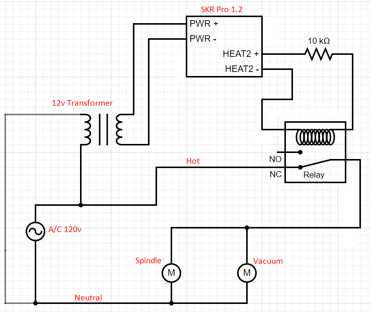
Here is the current circuit diagram for how I have it wired - hopefully I’m using the correct symbols for everything.
Once the new relay comes in, the only change I plan to make currently is to change the 10k ohm resistor from being inline on the HEAT2 + connection, to jumping the HEAT2+ and HEAT2- connections. Does that sound right? Again, not sure if that will fix the issue with M3/M4 turning it OFF and M5 turning it back on - that sounds like something with the firmware itself I’d assume but I didn’t see anything in Configuration.h / Configuration_adv.h that seemed obvious.
The heater is designed to be a variable output. For the relay you just need on/off control - it doesn’t provide for variable RPM. I don’t have the same board you do, but there should be a pin designated for “spindle” or “spindle enable.” It should be defined as digital on/off and is probably already mapped to M3 (on)/M5 (off) in the firmware configuration. As I understand things, M4 only factors in if you have a reversible spindle.
The 10K resistor is probably why your first relay is not working. I’m not sure what reference you used to think it was necessary. According to the product page, this (first) relay has a coil that draws 60ma, which shouldn’t be a problem for a 12V pin on your board. As for your second relay, on another topic on this forum, concern was expressed over the amp rating due to the high current startup of the routers.
Thanks for the quick reply. I had read in a thread somewhere on here (or something in the marlin docs? can’t remember) that 10k ohm resistor was needed to prevent a brief “blip” of 12v when the board powered up. The reason for it being inline was just my own inexperience in wiring circuits and not understanding what was meant by “pull up resistor”.
After posting my Edit, I removed it once I saw how/where the pin was enabled. Since this was put in the file by Ryan/Jeff/V1, I assumed it was not something particular to the heater pin. I would not put a pullup resistor on the circuit unless you experience a problem.
Edit: A pullup resistor with the emphasis on the ‘up’ would imply that the laser/spindle is expecting to see 12V when disabled. That the pin is pulled LOW (0V) to enable the laser/spindle. This resistor would go from a 12v source to the pin and would assure that the pin has 12V during powerup before the software takes the pin HIGH. This pin-low-to-enable is the behavior you are seeing with your M3/M4/M5 tests.
But with that said, what you are seeing does not match what I see in the firmware. In the firmware for the SKR Pro in configurationAdv.h, there is this line:
#define SPINDLE_LASER_ACTIVE_STATE HIGH
Which I’m assuming means that the enable pin should be HIGH to turn the laser/pin on. So I’m puzzled by the behavior as reported by your voltmeter.
You were correct. There were a couple things wrong with my setup - first I removed the resistor from the HEAT2+ line entirely and just wired up the relay directly to HEAT2 +/-.
At some point, I inadvertently switched SPINDLE_LASER_ACTIVE_STATE from HIGH to LOW when I was tweaking the firmware. I reverted that change and it looks like the problem is solved! M3 enables the relay, M5 disables it as I would expect.
Glad you got it working. If you experience problems with whatever you have connected to the relay coming on briefly before the board is fully booted, you will want to install a pulldown resistor for this configuration. That is you will want a 20K give or take resistor wired between ground and your heater pin. This assures that the pin is LOW until the board can pull it LOW.