I’ve Built an MPCNC (Burly), and I still have to upload the picture here on the forum
By the way, I need your help with the motherboard! I wanted all the possibilities that GRBL, as far as I know, offers and also planned to upgrade to the dual end-stop for AUTOsquaring so I’ve bought a Ramps board.
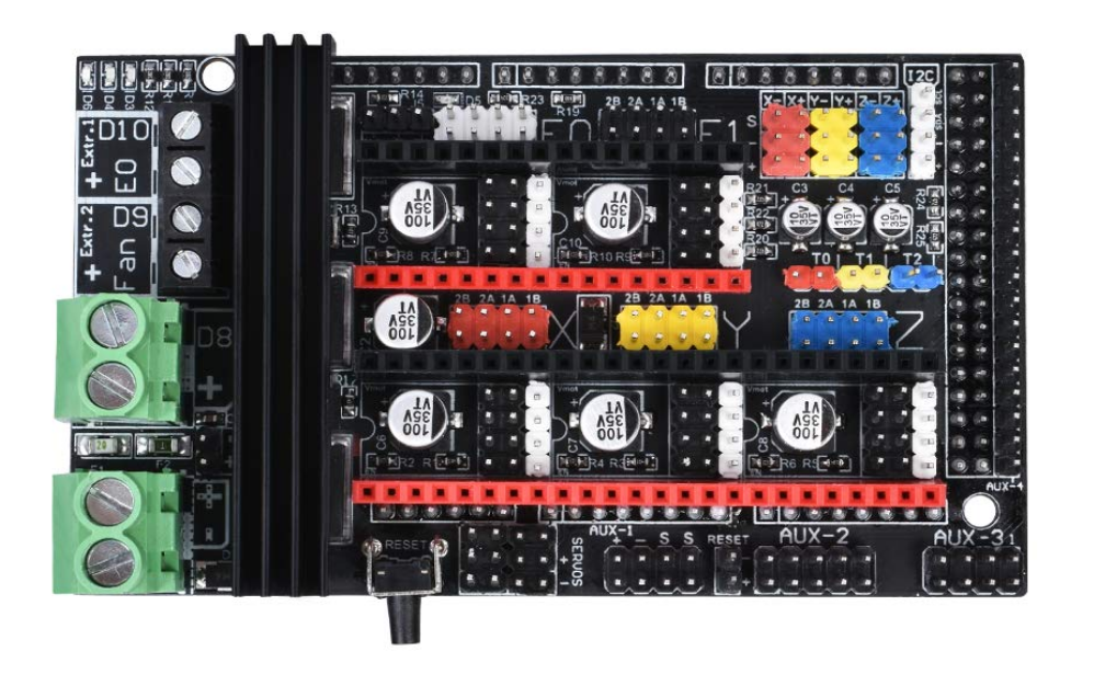
The Ramps is the 1.6+ version. I have to admit that now I’m slightly not happy for the choice since, apparently, is less easy to set up compared to the other version. The decision came from the fact that this 1.6+ is better and has also better hardware to avoid previous boards’ burn issues.
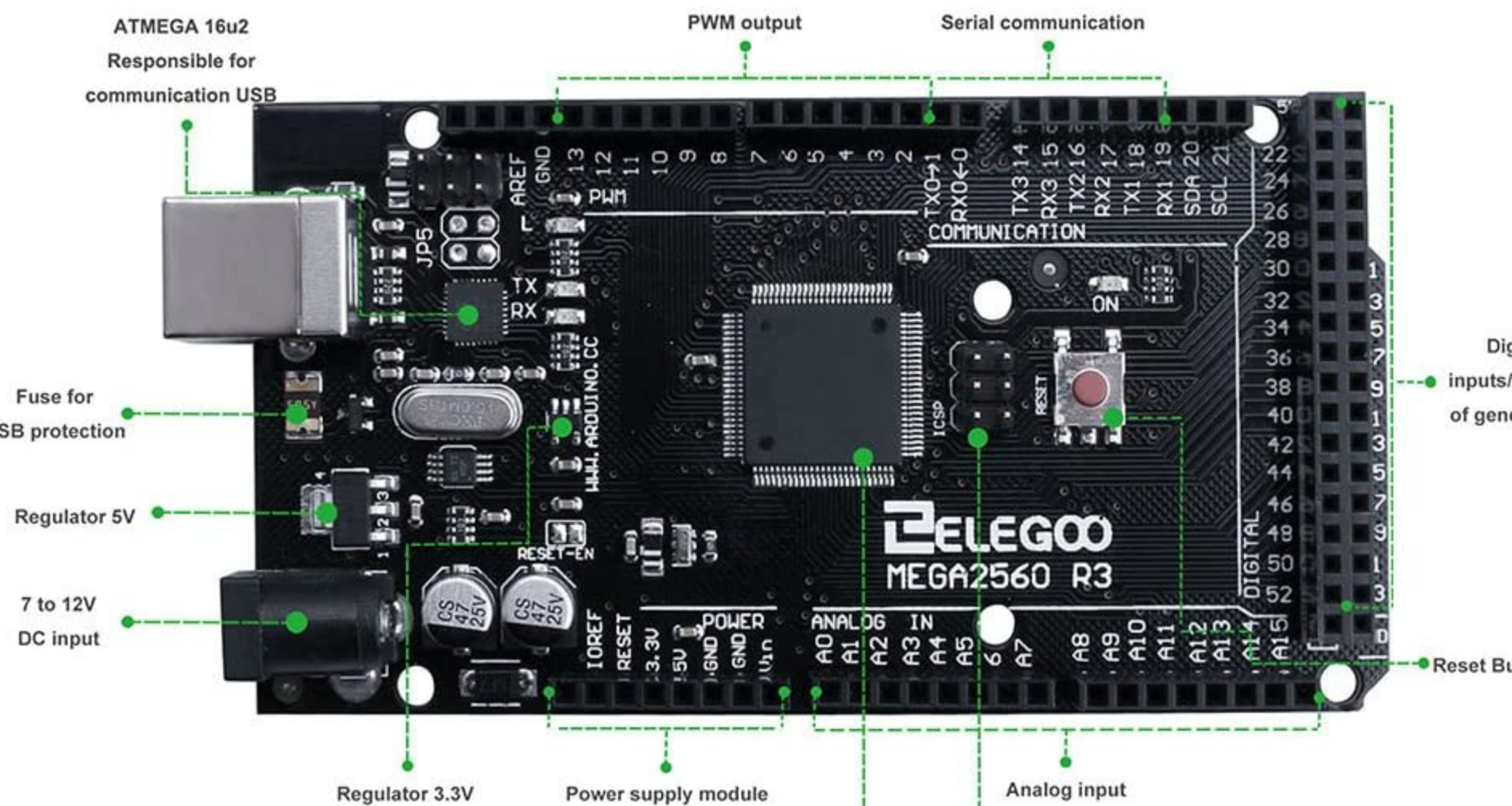
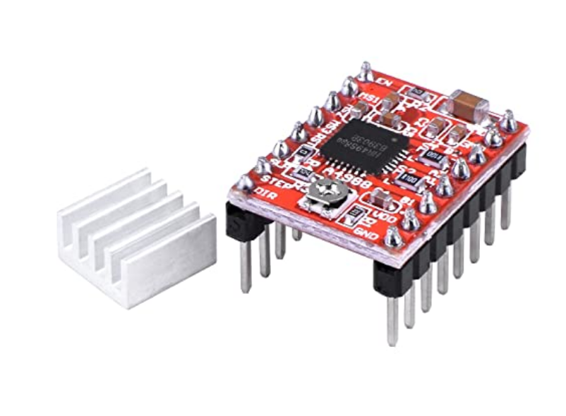
So I got 1 Ramps 1.6+, 1 Elegoo Mega 2560 mb and x5 A4988 stepper drivers.
I flashed the GRBL Mega-5X that I’ve found on this forum.
I was able to connect the board with UGCS but nothing more. The first problem is that I don’t know how to insert the jumper couplers correctly. I saw on the web that A4988 and DRV8825 are “special” so I need to put them between the black and white pin on the board. (The 1.6+ has 4 rows of pins per each stepper driver instead of the classic 3 ones)
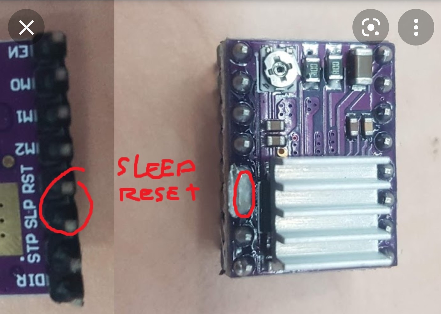
They kinda tell where to place the jumpers and to solder the RESET and SLEEP pins together (just for A4988 and DRV8825 drivers). So once I did this to test the X-axis (just 1 motor connected) I tried to send move commands with UGCS but the stepper doesn’t work.
Since I’m not an electrical engineer nor a programmer I have no idea of what is going wrong here! I wasn’t even able to find tutorials for the combination GRBL-RAMPS 1.6plus-A4988 which seems to be not so common.
Could you please help me with your knowledge so that we can make a sort of guide to help other people that made the same choice?
Time to grab your phone and show us everything… Put the RAMPS into the Mega 2560 with the drivers installed (at least the one you will be testing with) and then hook up the appropriate wiring. Take pictures showing us the power coming in, the wiring to the stepper and anything else that needs to be connected to get it started. That way we can see if you’ve been caught by any of the more common mistakes.
If swapping the cables to the display doesn’t fix the display then stop trying to fix two problems at the same time. Remove the display entirely for now.
You say UGS says it has connected with the board… if you send a $X from the console does it respond with an OK? If it does try moving whichever axis you have the stepper driver & motor connected to using the jog controller panel…does it move now? If not press reset zero and try moving it again. If it still doesn’t move ensure your 12v supply is good to the board? If all else fails post your GRBL config after sending $$ from the console.
EDIT: Also check the resistance of the stepper motor windings - there should be something like 3.5ohms per winding and the wires with that resistance between them should be next to each other in the 4way plug that plugs into the RAMPS
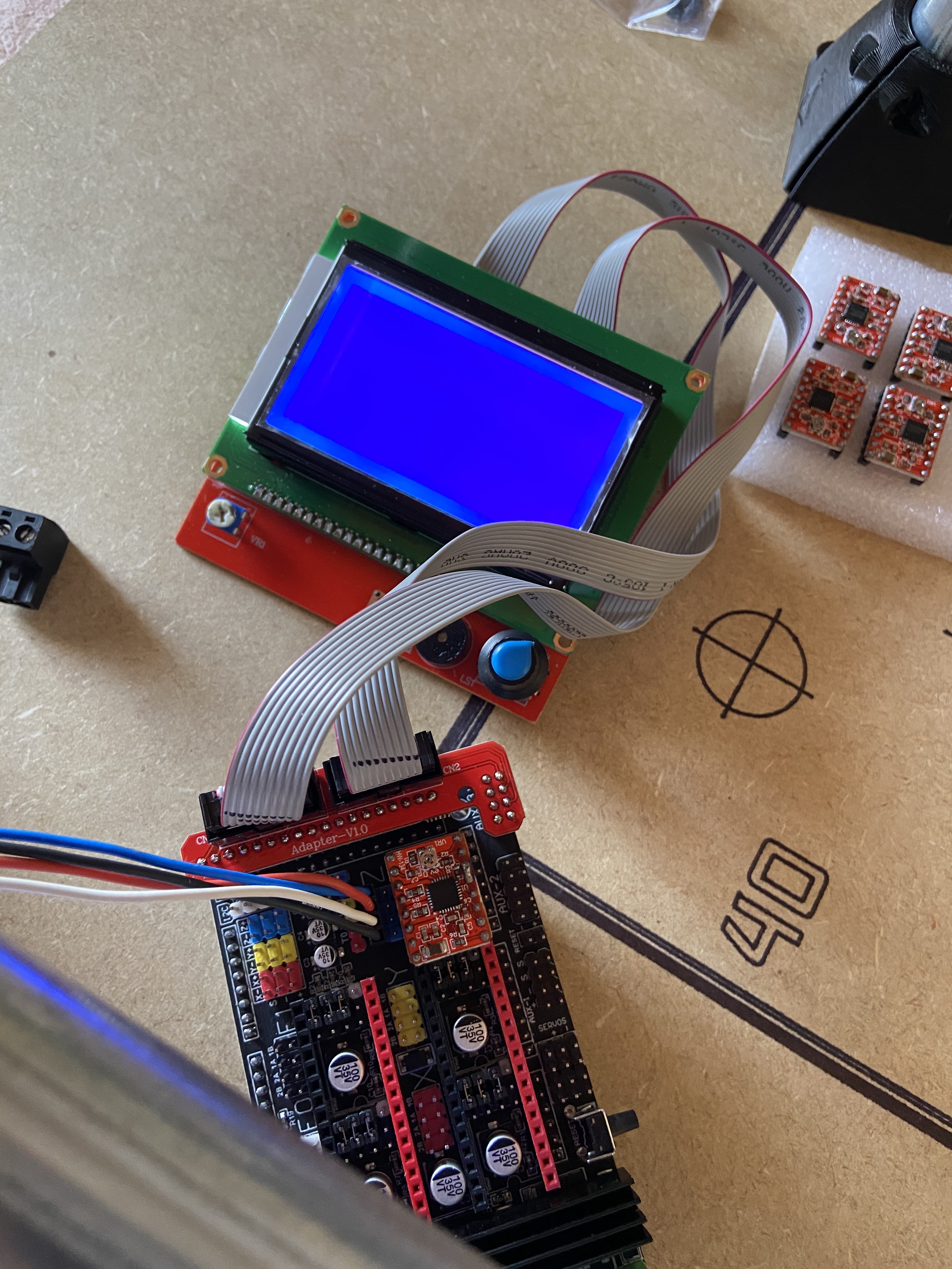
Another thing even more strange is that the ramps shield, until this morning, had a blue led [D3] turned on when connected to the power, while I was in UGCS i noticed that the LED turned off somehow and since then it won’t turn on anymore…I hope that the shield is not burned now.
@Slite Already tried, with one configuration is totally swiched off, with the other one it’s just back lit as in the picture!
@jeffeb3 It think so because I’ve had a quick look at the config file and I couldn’t find any LCD/display line code
Try…
Turn off soft limits with $20 = 0
Turn off homing cycle with $22 = 0
I don’t think $103, $104, $113, $114, $123, $124, $133 and $134 have anything to do with your problem but can’t be sure as I don’t use GRBL_MEGA…they are not in any of my GRBL1.1f machines. After the $X the software should report ready instead of alarm and it should be good to go.
It does not receive any current and the shaft is freely rotatable with one finger. I’ve measured the two coils and they have both 3.8 Ohms
I’ve also measured the voltage on the stepper’s Vref trimmer and it is (adjusted) 0,86
[I’ve flashed the firmware both in hex format and via Arduino with MacOs, if this can help]
@zappalang It looks like you’ve done everything correctly, at least at the physical level (though I use the DRV8825s, so I’m unsure of your jumper config). Now let’s see your config.h file. That will tell us a lot. You can also try flashing Ryan’s Marlin firmware to the board just to see if it works.
I do know this: I run GRBL 5XMega on my Lowrider 2. It was not easy to get it running the way I wanted. GRBL will enter the alarm state for a variety or reasons and will refuse to move anything at that point. Unless configured otherwise, when GRBL powers up, it is in the alarm state. You must $X unlock it before you can really do anything else.
OK… so I am thinking now we are down to checking the signals on the pins. I think I once had a GRBL_MEGA software that didn’t work because it utilised different output pins but once I found the software that worked for me I erased the software that didn’t work. I have a Mega2560 but not a RAMPS v1.6, actually it is a Mega2560Pro board and I know the outputs are as follows-
Xstep|24|
Xdir|30|
Y step|25|
Y dir|31|
Z step|26|
Z dir|32|
GND|gnd|
EN|13|
probe|Analog15|
X limit|10|
Y limit|11|
Z limit|12|
(the numbers are digital output pin numbers, apart from the probe which is an analog pin) So you could check, with a multimeter that your Mega 2560 digital pin numbers are attached to the stepper driver step and dir pins. I suspect they will be - then you will need to check for the signals when you command movement…Alternatively… flash this image…I know this works with those pins. grbl-Mega_v1.1f.20170802.zip (33.0 KB)
You have checked your +12v at the vmot and gnd pins on the drivers haven’t you?
Does the software report idle after the $X
Is there a particular reason you chose a MEGA2560/RAMPSv1.6 over the Uno/cnc shield?
Larry - no config.h file with GRBL…just the $$ file printed above. I find GRBL much easier than Marlin to get working.You have to either home it or bypass the alarm because the software has no idea where the carriage is and the alarm is there to make you think about what you need to do to initialise the job. There is much less configuration with GRBL than Marlin, and much less superfluous stuff to deal with. Marlin is superb for 3DPrinting but IMHO is not well suited to laser and router work.
I don’t know grbl as well as I know marlin. But if I had any trouble at all, I would be looking first at disabling homing. I know grbl will be in alarm until it homes if it thinks there are home switches, and it will also check them all the time, so they can be responsible for it not moving. I think you can disable those in $'s, but you might have to find an option in the config.
In order to help troubleshoot @zappalang 's issue, I think that file will be necessary. Checking signals on the non-PWM outputs as @dart1280 suggested is indeed a good troubleshooting technique as well.
I think we can make this work; We just need all of the information available to get us there.
Btw since the on the board some “power status” less suddenly stopped to turn on I’ve decided to give back both the boards and the shield.
I switched to a Mini Rambo board (I’ll try to work with double X motor-endstop and single endstop + hardstop on the Y), what do you think?
In the meanwhile I’m trying to learn how the machine works by doing some test cuts and I’ve found that what should be ø7.5mm holes result in 8mm x 9mm “oval holes”.
Checked the belt tension. I’m using a straight 2 flute 1/8 bit with Ryan’s basic Cut settings and Estlcam. Do you have an idea of what could be?
I have also a doubt: while it was making the holes (peel mode) the bit came off from the spindle and I had to turn it off. Then I noticed that by turning the spindle by hand the straight milling bit seems like slightly bent on one side. I tried with two identical bits, the one I’ve already used and another 100% new and they seems to be identically bent. I’ll post pictures. So it’s normal shape of the bit or maybe one of the collet got somehow “slightly deformed”? Because it seems to me to engage perfectly the shank.
Dammit. I’m way late here. But if anyone else finds this, the 1.6+ is configured for newer stepper drivers. 4988(maybe?)and drv8825(definitely) need the enable pins soldered. I had to do the same thing and was frustrated with myself for thinking “plus” meant “better”.
I didn’t see that mentioned here, so just throwing it out there.
Hi there, what do you mean solder EN pin? solder to which pin? What i have is this ramps 1.6+ with drv8825 v2 from btt and i am having the same problem. i will reflash the mega 2560 with a newer version of grbl which has the dual axis feature and see the outcome.
The only references I see now are for the sleep/rst pins to be soldered together, so it’s entirely possible i was mistaken about which pins I soldered.
I absolutely do not trust my memory to be accurate for anything before yesterday’s breakfast, so get ahold of the ramps manufacturer’s documentation before you do anything. That’s where I found my instructions.
That said, my memory does allow that it looked something like this when I was done.