Any interest in writing software for the MPCNC?

It’s coming along.

Next bit of coding is the toolpath cutting generation. So far I’ve created a service with zilch code. That was the easy bit. Need to do work out a javaScript scanline function that works for pixels and see how to adapt that to cutting bits.

Rob

Just added an exceptionally simple test to see if my way of generating a cutting path might work and it holds promise.

Created a 200mm x 200mm square, and passed the coordinates to a toolpath generation service. This simulates having a 20mm (yes I know, its dumb) cutting bit. The toolpath service generates a series of cutting paths based on the inside dimensions of the square. It takes no account of anything else at all but it demonstrates that the principle might work. I would assume that cutting out a square would involve cutting out the interior and then goinf around the square on the inside in a clockwise direction (assuming the bit is clockwise) afterwards to clean it up. This is very crude and very PoC level work.

An awful lot of work to go, but a very small step forward from an awful lot of thinking :slight_smile: The blue is a ‘cutting path’

Cutting version 1

1 Like

This is one part of code where intense unit testing is essential. Think of it as a log of every mistake you’ve found and you can just run the tests to make sure you haven’t repeated any mistakes. Playing whackamole with bugs in geometry operations can make you go nuts.

2 Likes

any updates? I see the last comment was over a month ago.

Hi,

Progress is being made. Its certainly not been fogotten or abandoned. For various reasons, I said I would take a break from this board and have stuck to it.

The current focus is generating the cut paths. I went down a few blind alleys trying to use other peoples code and adapting it for my use and then gave up and wrote my own scanline algorithm, for this I had to go back and find my old Foley and Van Dam book on Computer Graphics from when I was an undergrad. It’s in a unpacked box somewhere in the house but couldn;t find it, so had to order it a second hand copy from Germany.

Anyway, I’ve written my own scanline algorithmn, the reason for this is that it allows me to generate the first cut paths quickly and handles complex polygons and holes. e.g. A five pointed star with a hole in the middle is not a problem at all. Since I control the y axis, I can then work out the next cut line based on the radii of the bit. So I can now do inner pockets.

I’ve also written the code to do the interior outline of the shape, this is used to smooth out the scallops from the horizontal cuts.

The current little problem is automatically working out complex intersecting polygons with different depths of cuts. Its trivial to look at and do from a human eye, but tricky to automatically do. Current I’m using an R-Tree to hold the spatial information and the relationships of each polygon that intersects and trying to work out the sequence of cuts based on a number of heuristics. It’s a challenge, but I’ve only spent a week on it, I can’t find any information that might help me, so it’s very much one step forward and then two steps back.

Here’s a screenshot of a simple square.

image

The redline is the actual polygon to be cut, thats the design.

The blue lines are the high level cut lines to be done.

The greenline is the inner route for making the finishing cut.

Once I have these created, I’ll then generate some gcode. I have a high level intermediate code to hold this information and then will look at various techniques to work out the fastest way to traverse all the cutting points. However that is a non-trivial program that is technically impossible to solve, there is no way to generate the optimum cut path for more than about 20 points even with every computer in the world working on it. I’ll probably do what everybody else does and use nearest-neighbour with some more heuristics.

So not been forgotten, I am actively working on it and if I could find this sodding bug, I’d post a better graphics.

Thanks

Rob

2 Likes

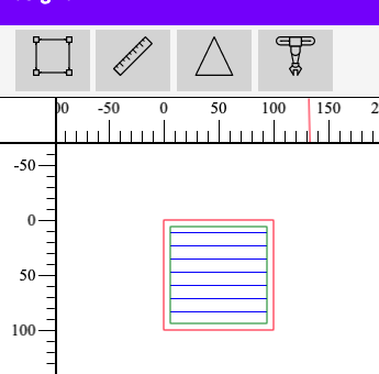
And lo and behold, I resolve one bug and can now generate this

image

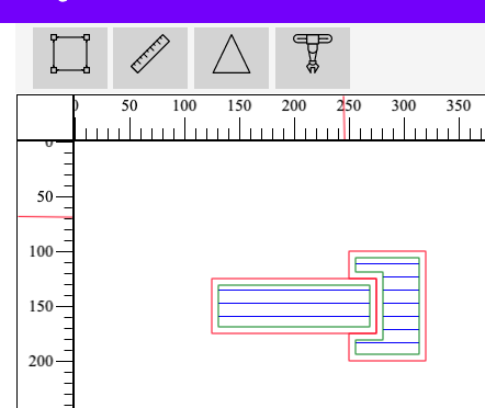
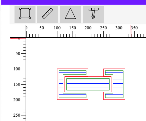
The actual input for this is two rectangles. Here’s the cartesian points that describe them.

    // Interlocking squares
    var points17 = [
        [
            125,125,30,
            275,125,30,
            275,175,30,
            125,175,30,
            125,125,30
        ] ,
        [
         	250,100,20,
            320,100,20,
            320,200,20, 
            250,200,20,
            250,100,20
        ]
];

The program has worked out that the first rectangle in the array has a depth of 30 and therefore its deeper than the second rectangl which only has a depth of 20. Therefore it automatically cuts out a chunk of the second rectangle. The program generates the cut lines as well as the inner path to make a clean edge.

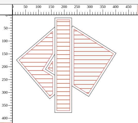
Here’s a more complex shape with three rectangles that intersect.

image

More complex polygons will also work, I use rectangles as that only has four points and I can do the maths in my head, whereas a complex star shaped polygon might have 12 points and I have no idea what the ‘right’ answer is.

A lot of this is new to me, so I have to go back to first principles to work out what I need to do, so it’s a bit slow, but it is coming along. The aim is to see how much I can do automatically before the user steps in.

Rob

7 Likes

Work is still going ahead on this. Sadly due to a design error, the last six weeks of work has been to no avail.

So back to the start for some of the design work.

The joy of coding… (not).,

Rob

2 Likes

I like this project and I admire you because you really have guts to start with such a big project all by yourself. If I were to start such a project I am sure I would never reach even the first milestone :smirk:
I did some programming some time ago, but have absolutely no experience with java script, electron and graphic programming in general. Since I am used to C++ programming I always wonder if java script could possibly be fast enough for handling graphic calculations - especially when its done over a webinterface?
I also like the modular and multi-platform aproach.
Already thinking of a nesting module like that one here that could be integrated into your software :slight_smile:

@ragadinks

I’ve written software projects by myself so this isn’t that unusual. My last one was for a traffic checking system for IOS and Android. Sadly it didn’t make my any money :), so back to my core skills, running large complex IT projects.

I don’t know Java at all, I know C pretty much inside out (I used to develop C compilers) on Unix. I use JavaScript as it’s pretty much cross platform and I like it. I do know other languages but I kinda like JavaScript. it has a rich library, not as much as Perl but not bad.

Javascript is fast now, Google has spent a lot of time on JIT compilation and it flies. For what I want, there’s no issues with speed, C is faster but the dev time is a lot longer…

I wouldn;t write an OS in JS but its good enough for clients.

My issue was I didn’t think though some of the use cases fully enough and found one that simply wouldn;t work with my approach. I was trying to automate as much as possible and found some issues over the cutting order for multiple intersecting polygons. There isn’t a clear answer so I had to roll back code and handle it in the UI. These things happen, so grin up and start again. Having somebody to bounce ideas off might (or might not) have helped.

I once junked a year of research in mathematical formal methods, so thats the way the cookie crumbles.

I think I have a simple soluton but I need to spend some time writing other software to validate it.

Thanks

Rob

1 Like

Have you seen webassm and the compilar that creates webassm from C++ code (drawing a blank on the name)? It seems awesome. I write modern C++ for Linux applications (backend stuff for robotics) in my day job. It sounds like a fun way to make a website :slight_smile:

https://emscripten.org/docs/compiling/WebAssembly.html

Emscripten is the one I read about a while ago. It seems like complete magic.

Yes - I recently came across webassm and this small example when I installed the newer clang++ compiler on my linux box. I am really fascinated from this aproach because as far as I can judge you can create a native executable and with some modifications (mostly makefile stuff I guess) a web application.

As far as I understand the clang compiler is a frontend to the LLVM compiler infrastructure and generates some sort intermediate bytecode that then can be translated into different targets - webassemby (javascript…) being one of them.

Once I tried out an example and was astonished how well it behaved in the browser. Wish I had more time to dig deeper into it.

@rwillett
I really wish I had your background :yum: Especially when it comes to mathematics I deeply regret my lack of a higher formal education.

Where in a real world situation would it be necessary to cut multiple intersecting polygons?

You mean you had the user let decide which polygon has to be cut in what order?

I have to admit that the details of graphics programming is far over my head and I just dont have enough spare time to dig deeper into it, but when I can do some testing or something similar for you just let me know, ok?

1 Like

Most of the maths I use is from junior school.

Intersecting polygons are pretty common, imagine cutting a foam bed for a camera to slot into, the base of the camera is not a rectangle, it has cut outs for hand grips, the lens (or the lens barrel), these are all probably designed as different polygons with different depths.

The issue for me was that I was trying to do all of this automatically and sometimes it’s not obvious when there is an intersection which should be the ‘master’ polygon. Without an intersection it’s quite easy, though islands and holes complicate the issue.

The solution is to move it back up the stack to the UI and resolve issues there.

I wastrying to be too clever and got burnt.

Rob

1 Like

Finally had time to work on the software over the weekend and have managed to put a layer system in place for drawing objects. Whilst this may appear to be trivial, it took quite some time to get it right as the model for this in fabric.js isn’t obvious. I also took the oppotunity to rewrite a lot of the menu code so that as objects are moved back and forwards, the menus update to only display allowable options. i.e. if an object is at the front, then it can’t be moved forward anymore. This is important for work later on.

Now this is working, the next step is to write a bidirectional form interface allowing the user to enter information on the webpage that is attached to the object, e.g. height, width, rotation, bit size, bit direction, bit depth etc. This should (famous last words) be easier than before.

Once that is done, I can get back to the most important bit, generating the cut paths for all the objects. The problem before was I had to generate the objects the objects in the right order, the Z-Index and I simply got the basics wrong. Hopefully that is now corrected.

The moving things back and forth can be seen here.

2021-06-14 18-25-59.2021-06-14 18_27_28

Thanks

Rob

7 Likes

Finally managed to get bi directional forms working. In simple English, this means that I can set the height and width from a simple input field onto an object such as a rectangle, and as I change the rectangle using the mouse the height and width are automatically updated. This is needed to provide accuracy, as using the mouse is only so accurate.

It turns out its slighly more complex to write than I thought as propogating events in Angular and electron.js is a whole lot harder than Angular 1 and some hacks need to be put in place whilst I try and work out whether or not to put a simple message bus in which seems like a step waaay to far.

Anyway after spending two nights debugging a JavaScript method which turned out to be I was passing a string holding a number rather than a number <doh> basic JavaScript schoolboy error, I got it working.

The GIF below shows it working. I really need to learn CSS or SASS or anything to get the design right, but that’s a job for another year. This basically means I can enter numbers and get super accurate measurements which we need for a CNC machine. Big step forward as I now have a coding template for this :slight_smile:

2021-06-22 21-27-11.2021-06-22 21_36_36

4 Likes

Finally got to a point where things are taking shape, perhaps not a good shape, but better than before :slight_smile:

So we now have bidrectional forms, with zero validations, works. I can change the height and width, rotation etc. I can also set the CNC bit size, trivial at the moment. You can see the values change as I move things around. There is zero validation, checks or formatting.

Now we have a zindex, we can move objects backwards and forwards. This is the key change from my previous cockup. So an object on top of another object has priority over the underlying objects. Note the plural. So a shallow cut on the top object is more important than a deep cut of any of the objects behind it. To make this work, I need to automatically cut shapes out of the objects behind the higher object. Clearly the next highest object has priority over the underlying objects and so on and so on.

So here’s a longish demo that demonstrates that. I have different sized CNC bits with different colours to demonstrate the cuts that would be made. I still haven’t added in doing the edges or insetting the CNC bit in this version, I have the code. I wanted to check that the logic I now have works. The shapes are NOT updated for the cuts, that is the correct behaviour, I just need to see where the CNC bit would go, the rectange is still a rectange in the design, just that bits of it are not cut.

Hope this is clear.

Rob

V1_Update_12_07_21

6 Likes

And as I’d already written the code before, here’s the edge cutting lines. Nice when the code just works for once.

I offset the milling area by the radius of the cutting tool to allow the tool to go around the edge. This should produce a clean edge. I’m sure there’s loads of rules about directions of cut and number of flutes and speed but for the moment, this is enough for me. Get it working first and worry about optimising it later.

Screenshot from 2021-07-12 21-05-46

6 Likes

I’ve now the written the code to join the cut lines together. I had the code to cut the horizontal lines but no way to join the lines together. We also need to lift the CNC bit for some travel. paths, e.g. where we have a higher priority cut above it.

The green lines below show where a lift would be, the red lines show actual cuts You can seefrom the cross, that the left and right sections are their own cut and there is a green line indicating that the bit needs to lift.

I have removed the outside edge code so I can see what is happening.

The code to join the lines together will never be 100% optimal as it’s basically the Travelling Salesman problem. there are not enough resources in the universe once one goes beyond around 20 points. :slight_smile: This solution is based on Nearest Neighbour and uses a Kd-Tree to work out the clostest point.

Next step is to join the different blocks together. and that will use yet another Kd-Tree.

Once this is in place, work can start on converting cutlines and lift lines to gcode.

Joined up lines

I love the whole idea of what you are doing and would love to help out, but I suck at programming for computers, lol.
I read over your first post and noticed that this would be to generate g-code. Were you wanting it to be able to connect to an external control board to stream out the g-code, or just generate a file that something else would handle? Just curious what you were aiming for.
Keep up the great work!