Ok, I need to mill out a 3d void from my material. I have the shape and contour of my void modeled in FreeCAD. In FreeCAD I take that “void” model and remove it from another block of material leaving the proper shaped void in the larger material. How do I transfer that to EstlCAM or some other CAM software? I know how to use Estlcam to cut a 3d stl and that works well for me. But how do I tell Estlcam that it’s not a 3d model but a 3d void?
I’m hoping my question is making sense. The void in the material I need milled out is very complex. There should be no reason a taper ball nose bit can’t cut it all, just trying to figure out how to transfer this 3d contour void into CAM.
Estlcam can import an .STL file, and will generate Gcode to carve it out, but you don’t get a lot of choice in what you carve. I believe that it will attempt to carve the whole solid, and not just a void in the middle. About the only real choice is holding tabs, but maybe if you are leaving holding tabs all around the outside edge?
I’ve never tried it myself, because I have always managed with Ryan’s instructions there, not needing so complex a shape in the end.
I’m have trouble understanding your question. Some screen shots of the modeled parts would be helpful. Also I’m a Fusion 360 user with only an passing understanding of EstlCAM.
So as a placeholder, I’m imaging the need to create a mold for half of a golf ball. You need to send a model of the mold to your CAM program. You cannot use a model of half of the golf ball and somehow tell the CAM to “invert” it. If I understand your description correctly, you need to send the “larger material” to the CAM software. As long as the STL you send to the CAM represents the void as you want it, it is just a relief carving. It doesn’t matter that it dips down.
Depending on your stock and what you are trying to accomplish, you may have to play some “games” with your model or with CAM, but without a deeper understand of what you are trying to create, I cannot guess at the workarounds you might need.
You will need to create another STL using the first one as a cutting tool or mold.
There are several programs that can do that. Use YouTube to find instructions using some software you are comfortable with. But the process will look something like this.
Import your current STL. Create a simple block or sphere or something that will fill the “void”. Then use the software to do a boolean operation that will cut the STL out of the simple shape. Then you can delete/remove your original STL.
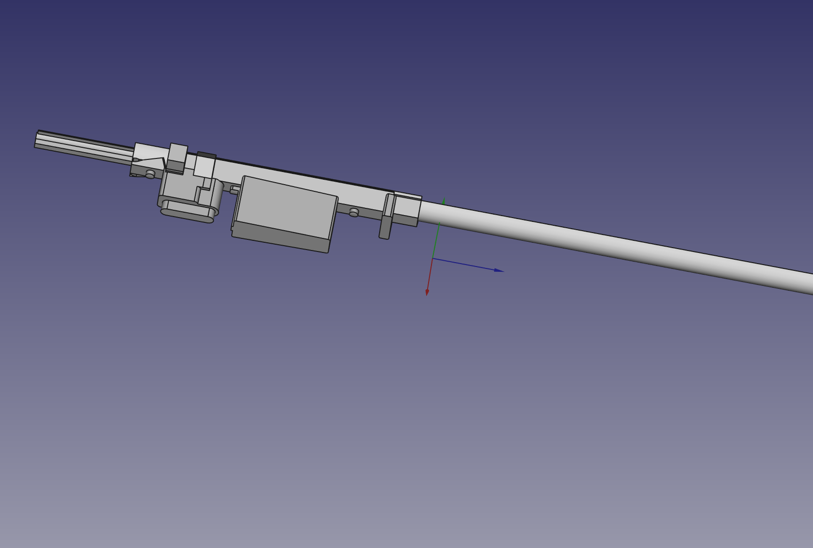
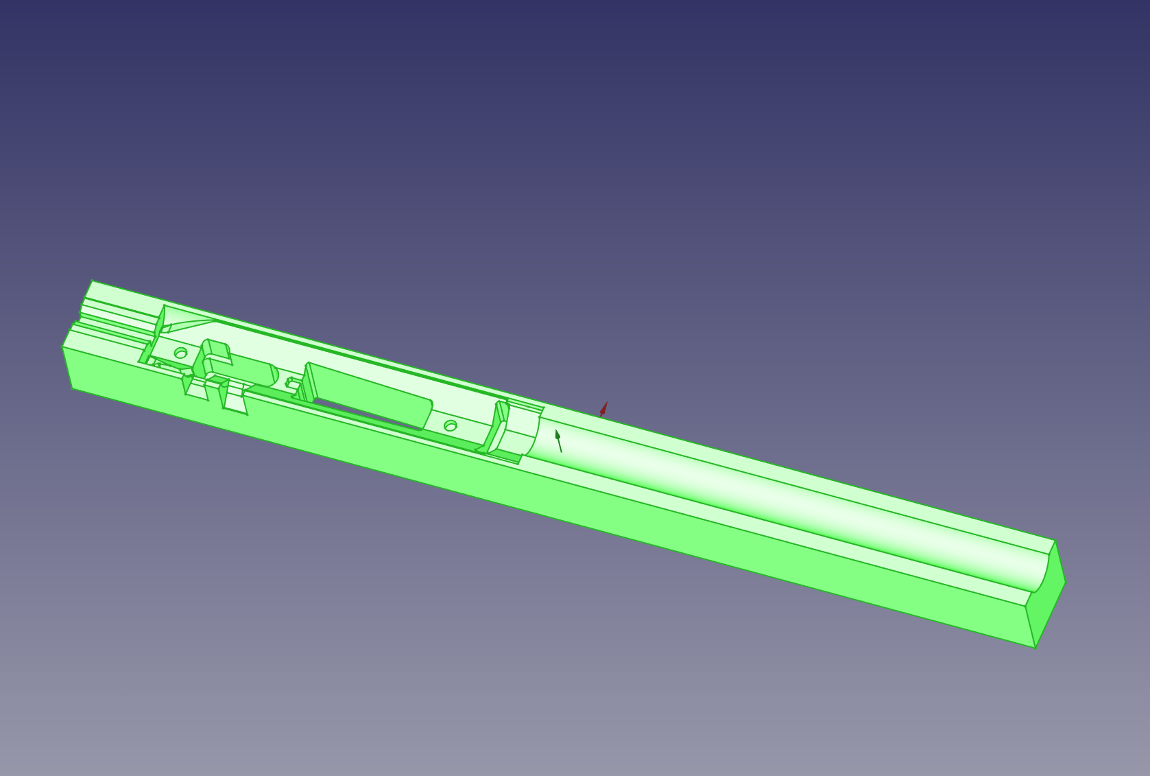
Here are my two models: inlett.stl is the void I want to create. inlett_result.stl is what it should look like when I’m done. Of course this is a two side operation, I get that. But for the sake of this conversation, I’m really only interested in the top down, not the bottom up.
I suspect the problem you are facing is that you did not model the side you want to mill as up (positive Z). A quick look inside of EstlCAM did not yield a way to define a different orientation for the model, but as said, I don’t use EstlCAM, so someone that is more familiar with the program may identify a way.
But the easiest solution is to just rotate the STL. You may be able to change the orientation in your CNC program, but if not (or if you don’t want to go to the work), most slicers for 3D printing allow the saving of an STL. So bring this model into your slicer of choice, rotate it so that the side you want to mill is up, and save the STL.
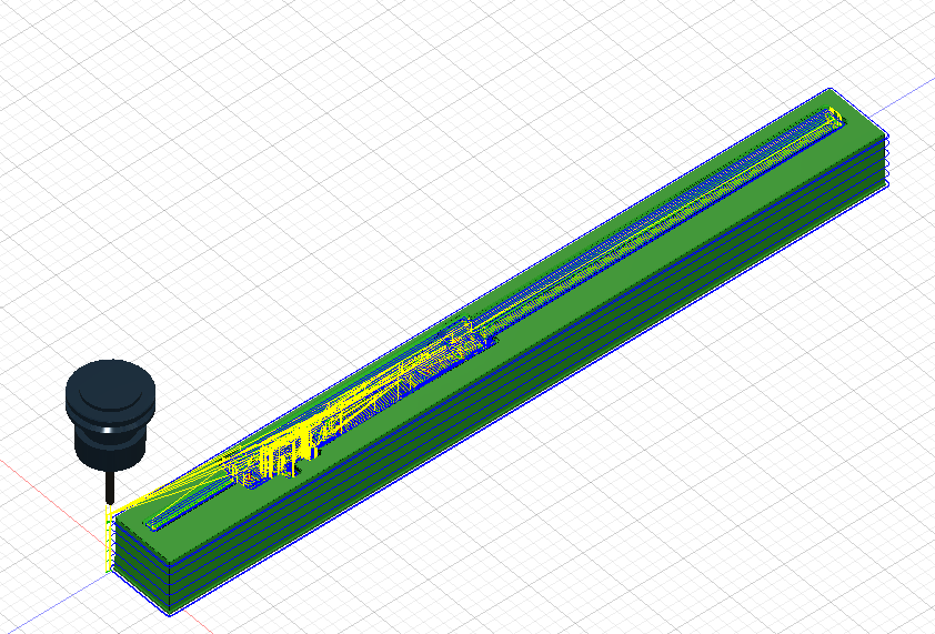
Using Fusion 360 I can bring in an STL and then “cut it out” from the stock material I am using.
Then using the CAM side of the program I can then mill out the shape.
I have used this to make “tool holders” to hold equipment in pelican cases.
I am cutting foam so the result is not super accurate as the foam bends as it is cut, but the result is a snug fitted foam insert for the case.
Typically I do a top and bottom piece that clamps the tool when the case is closed.
Will try your file tonight and see what can be done.
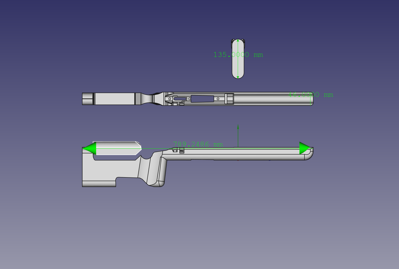
Ok - Ran it through Fusion360. Seems to work ok but I would only be cutting foam (or similar) because it has a very deep (50mm) cut depth. Maybe a 3mm bit could do it but I usually cut with 6mm to go that deep. Otherwise I’d be cutting thinner materials in layers and then “stacking” the result.
What are you trying to cut, and how accurate do you need it?
I make custom rifle stocks by hand, or that’s how I previously did it. I’m hoping to work it out so I can use my MPCNC to do the lion’s share of the work. I’ll be cutting into laminated cherry, black walnut, oak maybe. I think I’ll break it down into a bunch of jobs, using the bolt holes as my indexes, use 1/4 inch to clean out the 85%, then some smaller bit (ball nose maybe) to do finishing passes. I’m a linux guy (31 years of it), I like Estlcam (wine, works great) , FreeCAD (it has a CAM side also), DeskProto seemed to have generated some good looking GCODE for this project also (just have to figure out which processor to use with Deskproto). Anyway, Sounds like most of the feed back I got on this was common to what I understood, however, the fusion 360 CAM output looks very promising. I may have to bite the bullet and load windows somewhere and get fusion 360. Also, I don’t have to cut all the way through, I plan on making this a two sided (four sided actually for the stock contours on the sides) job. So I feel confident with the other work I have done with the MPCNC that I can make this work. I was just hoping for a silver bullet with the CAM side of things.
Another volley of questions (and I will do some tests with Estcam too), I have what is essentually a “V” valley in the middle of this job “\_/” , the bottom part is a no brainer in Estlcam, it’s simply a slot. The sides though, is there a 2d way to cut slopes with EstlCAM? or do I just do some sort of stacked chamfer to achieve a sloped sided void? Or should I just stick to a 3d cut and let it figure it out?
Anyway, I think I’m asking questions that I can probably figure out with some more time and testing. I really appreciate this community though. You guys and gals are great and leave lots of really good input. Thank you very much for that.
Use Fusion for work so have many years of driving it. When I made a Lowrider it was a no brainer to use the CAM side of Fusion. Fusion offers various 3D contours in the CAM engine, I have not used ESTLCam so not sure if it will what you need.
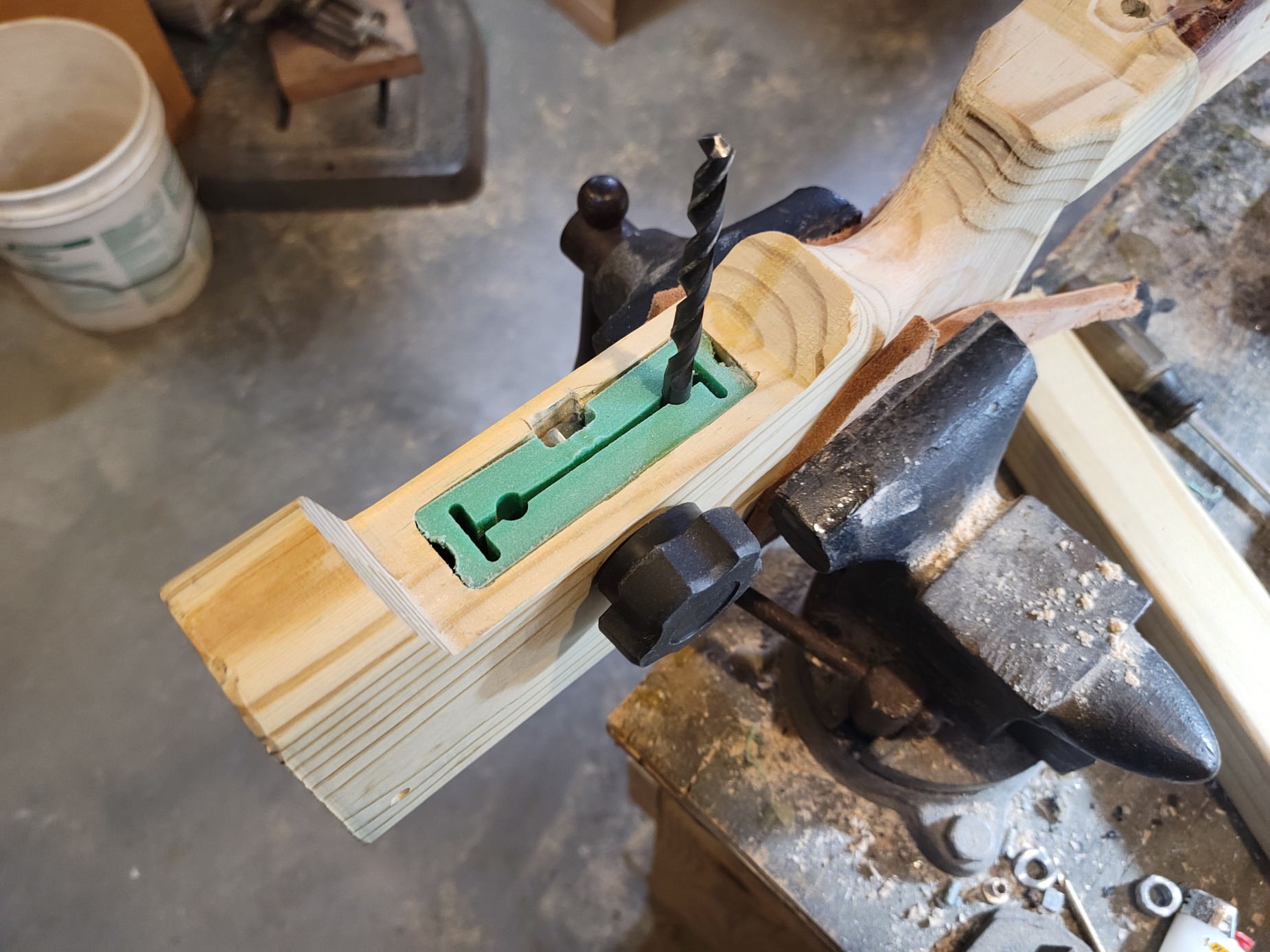
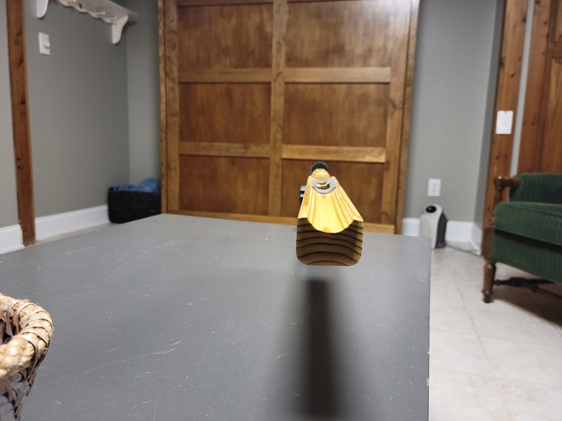
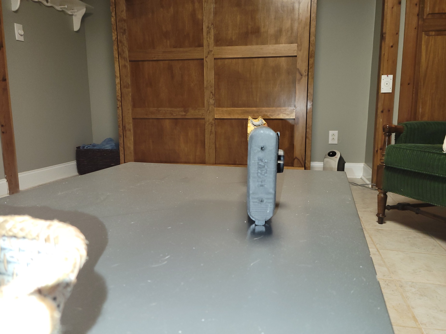
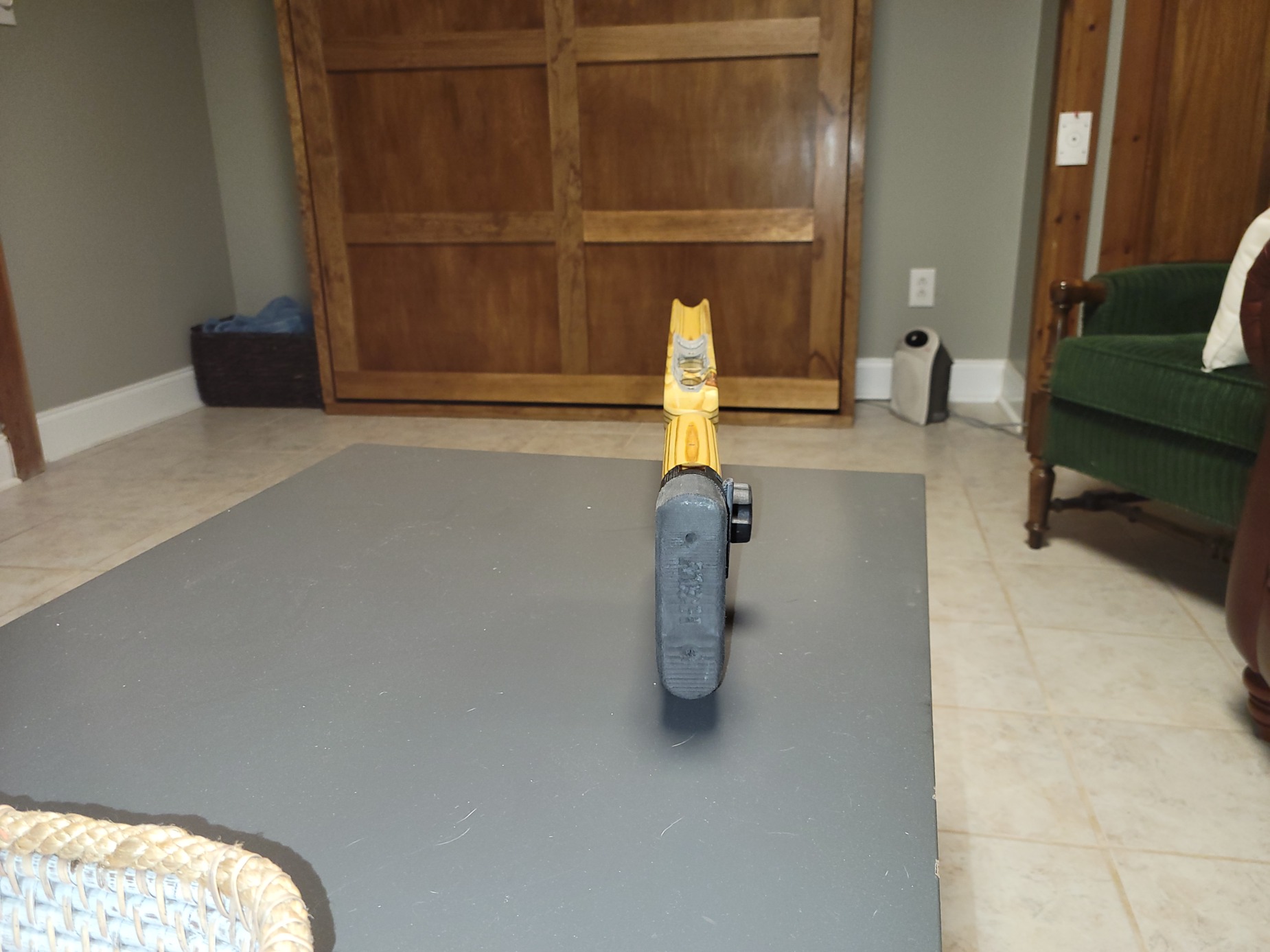
Actual progress. Thanks again for all those who posted advice on doing this. So far so good. Doing a test run with scrap wood before I make my “cherry wood” laminated rifle stock blank… This is playwood and pine I had laying around shop to see what things I need to tweak on my jobs.
Just remember to adjust the speeds when going to real wood.
I cut a test piece, then went to marine ply and forgot to slow it down.
Smoke started coming off the job
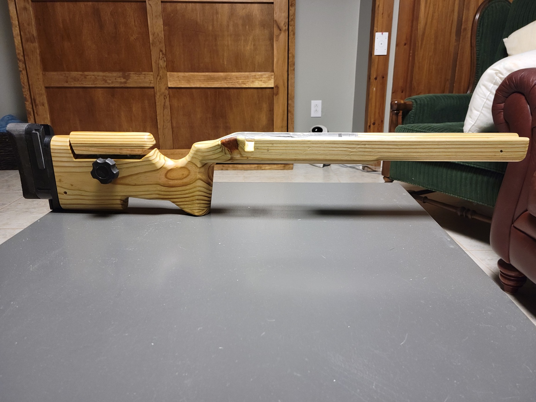
Here are some updated photos. This is NOT my final stock. This is V3 made of pine I had laying around. Final stock will be laminated black cherry. I wanted to work out all the bugs on this one. This one is sporting my adjustable buttplate and cheek riser. All made on the MPCNC along with the stock. Very happy with the performance of the MPCNC.
I have a question about locking steppers: Some of these jobs take a long time (nothing new to you guys) so my procedure has been the following:
Pause the job with cncjs (wait for spindle to stop moving)
Power off spindle
Do an M114 to get coordinates, write them down.
Poweroff rambo, leave computer with cncjs running, turn off monitor
Next day:
Power on monitor
Power on rambo
M17 to lock steppers
Enter in all the coordinates with G92 Xxx.xx Yxx.xx Zxx.xx
Power on spindle
click Continue in CNCJS
These steps normally work.
Sometimes, however, I forget to do the M17 and then my spindle tears through my work…
Anyway to have M17 execute when the rambo is powered on? This seems to be the step I miss the most and I can see no reason for the way I use the MPCNC that if there is a way to enable this, it would help me out.
I don’t think there is a way to have them enabled by default in the firmware. grbl has that option (well, if you want your motors to stay enabled at all, they are enabled all the time).
But you could add whatever gcode to the start of your machine if you have a screen and SD card.
Maybe I misunderstand but I think you want to send an M17 before you do anything else right?
If that’s the case…I created a button in cncjs I labelled “Engage” and it’s the first thing I click before any other commands (other than an M114 maybe). Engage for me is a 1/2mm jog x and y and 10mm z.
The z is so I can take the parking blocks out from under my gantry. But the effect is that it fires up the steppers.
In any case…maybe creating an Engage button in cncjs with M17 in it and always making that your first action would help.