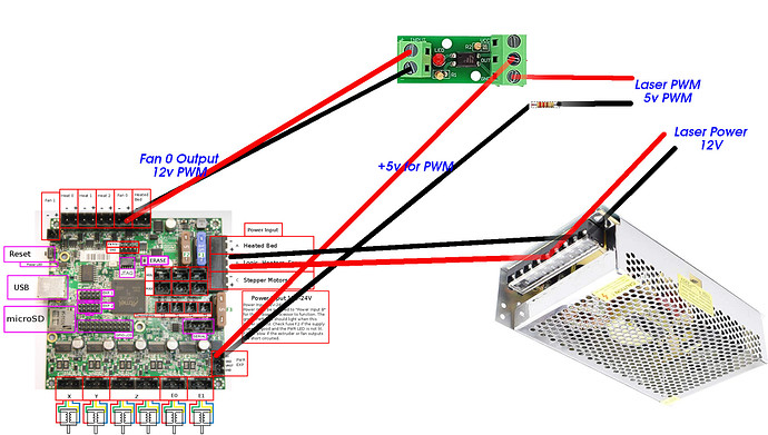
Archim Laser configuration

yeah, I didn’t dig that far into it since I’m new to the firmware but I’m just glad it works :slight_smile: For my motor/ESC I just send the M280 P0 S70 and that starts my needle cutter at 9400RPM every time :slight_smile: it’s working perfectly now!! so very grateful you guys were willing to work through this with me

edit: I should mention that for my ESC I’m only using the single wire going back the ESC. The ESC is powered by the 12v comings from my power supply that powers the motor. I only highlighted the positive and negative above since they were used to control the servo.

1 Like

Did they ever get back to you about this? I’m in a similar position I have my laser working using the logic lever converter but when I do pictures it seems like it can not change power levels fast enough. any help would be great. if I need to I can start a new topic.

Archim should be fine with the current build of the firmware.

Hello all… Have read through the whole thread, and it wanders a bit, so I am hoping for a up to date summary?

I’m about to add a 5V logic Laser, and intend on working with the latest 2.0.7.2

Wanted to confirm that in the latest V1CNC Archim 1 2.0.7.2 that pin 53 does actually work for PWM at 5v?

From the Marlin Docs (edited to ref pin 53):
For example, to define pin 53 as the second fan just add this line to Configuration.h :

#define FAN1_PIN 53 // 2nd fan output attached to laser TTL input

You can then control the laser from your G-code using M106 P1 , like so…

M106 P1 S0   ; Laser off (P1 = 2nd fan output)
M106 P1 S128 ; Laser at 50%
M106 P1 S255 ; Laser at 100%

I have not tested it but I belive the Archim’s have been edited to use inline commands instead of M106.

Some of the testing I did.

So then I’d use: the M3, M4, M5?

Pins

Alternatively, you could configure the following to use M3, M4 and M5.

In the pins_MYBOARD.h file for your board make sure the following pins are defined:

#define SPINDLE_LASER_ENABLE_PIN xx   // digital pin
#define SPINDLE_LASER_PWM_PIN    yy   // digital pin - MUST BE HARDWARE PWM
#define SPINDLE_DIR_PIN          zz   // digital pin

Selecting the pin for SPINDLE_LASER_ENABLE_PIN is fairly easy. Just select any free digital pin with a 0 to 3.3V-5V logic level.

I still see that El-Jefe’s issue on Git Hub is still open… So did we ever find a pin for PWM on the Archim1?

Yes, The Mcodes. Have a look at my test gcode in that thread. Inline commands are a bit different and the codes are not really needed.

As far as I know 53 has been tested and works.

Edited, because I found out more…

I’ve done a bunch of searching for actual definition of the 3 define settings… Seems that the Marlin documentation I’ve found so far is lacking around these 3…

what I’m assuming is:

  1. SPINDLE_LASER_ENABLE_PIN This is “power ON” for the laser. Needs a normal digital out pin. Either to supply the 5V from the board, (or to control a relay for the 12V supply?).
  2. SPINDLE_LASER_PWM_PIN is Hardware PWM, this controls the intensity of the laser.

Havent found any info on “SPINDLE_DIR_PIN”…

Just finished re-building my Lowrider with new bearings and longer Z tubes. Going to do some testing this week and hook up a scope on pin 53.

Well it looks like PWM is not supported on Archim…
I guess Archim will still be waiting on the ticket that @jeffeb3 opened for PWM on pin 53.

Results Bellow compiling with Platform IO, with:
#define SPINDLE_LASER_ENA_PIN 70 // digital pin J20 connector pin22 (PA17 aka digital pin 70)
#define SPINDLE_LASER_PWM_PIN 53 // digital pin - MUST BE HARDWARE PWM J20 connector pin17 (PB14 PWMH2 aka digial pin 53)

Processing DUE_archim (platform: atmelsam; board: archim; framework: arduino)

Verbose mode can be enabled via -v, --verbose option
CONFIGURATION: https://docs.platformio.org/page/boards/atmelsam/archim.html
PLATFORM: Atmel SAM (6.3.0) > Archim
HARDWARE: AT91SAM3X8E 84MHz, 96KB RAM, 512KB Flash
DEBUG: Current (atmel-ice) External (atmel-ice, blackmagic, jlink, stlink)
PACKAGES:

  • framework-arduino-sam 1.6.12
  • framework-cmsis 1.40500.0 (4.5.0)
  • framework-cmsis-atmel 1.2.2
  • toolchain-gccarmnoneeabi 1.70201.0 (7.2.1)
    Converting Marlin.ino
    LDF: Library Dependency Finder → Library Dependency Finder (LDF) — PlatformIO latest documentation
    LDF Modes: Finder ~ chain, Compatibility ~ soft
    Found 4 compatible libraries
    Scanning dependencies…
    Dependency Graph
    |-- 0.4.5
    | |-- 1.0
    | |-- 1.0
    |-- 1.0
    |-- 1.0
    Building in release mode
    Compiling .pio/build/DUE_archim/src/src/HAL/DUE/DebugMonitor.cpp.o
    In file included from Marlin/src/HAL/DUE/…/…/core/…/inc/MarlinConfig.h:49:0,
    from Marlin/src/HAL/DUE/…/…/core/serial.h:24,
    from Marlin/src/HAL/DUE/DebugMonitor.cpp:25:
    Marlin/src/HAL/DUE/…/…/core/…/inc/SanityCheck.h:3075:8: error: #error “SPINDLE_LASER_PWM_PIN not assigned to a PWM pin.”
    #error “SPINDLE_LASER_PWM_PIN not assigned to a PWM pin.”
    ^~~~~
    In file included from Marlin/src/HAL/DUE/…/…/core/…/inc/MarlinConfig.h:50:0,
    from Marlin/src/HAL/DUE/…/…/core/serial.h:24,
    from Marlin/src/HAL/DUE/DebugMonitor.cpp:25:
    Marlin/src/HAL/DUE/…/…/core/…/inc/…/HAL/DUE/inc/SanityCheck.h:56:4: error: #error “Features requiring Hardware PWM (FAST_PWM_FAN, SPINDLE_LASER_FREQUENCY) are not yet supported on DUE.”
    ** #error “Features requiring Hardware PWM (FAST_PWM_FAN, SPINDLE_LASER_FREQUENCY) are not yet supported on DUE.”**
    ** ^~~~~**
1 Like

You are correct on the first two, and spindle direction is a digital out to control reversible spindles that have the feature. Iirc in non laser mode Marlin uses m3 for reversing the spindle direction. For laser the direction is of course irrelevant… so Marlin uses m3 laser pwm commands when laser mode is enabled.

The laser enable is I think intended for a 12v relay… mine has one that guarantees no accidental laser during boot up (some pins like to go high during boot, and it it happens to your laser pwm pin, you will want a relay to prevent issues).

I read comments above (long thread so hope still relevant) about the pwm output voltage and using a multimeter. you can’t measure pwm with most multimeters (without additional circuitry anyways), you need an oscope.

Thanks Kev,

Im stuck trying to get pin 53 to work, as using “#define SPINDLE_LASER_PWM_PIN 53” which should be a valid PWM pin for Archim gives compile errors:
Marlin/src/HAL/DUE/…/…/core/…/inc/SanityCheck.h:3075:8: error: #error "SPINDLE_LASER_PWM_PIN not assigned to a PWM pin."
and
Marlin/src/HAL/DUE/…/…/core/…/inc/…/HAL/DUE/inc/SanityCheck.h:56:4: error: #error "Features requiring Hardware PWM (FAST_PWM_FAN, SPINDLE_LASER_FREQUENCY) are not yet supported on DUE."

Using Fan 0 gives 24V PWM logic (on a fancy multimeter). Im assuming that is due to 24V input supply. Im going to hook up my cheapo oscilloscope and confirm visually later today.

Seriously considering throwing in the towel on Archim… For those of you using the SKR PRO1.2 that Ryan sells, how happy are you with that board?

Ok hoping for some guidance from those of you that delve deeper into Marlin than I. Everything bellow is my Guesses… Either I suck at finding the right Marlin Documentation, or it just doesn’t exist…

Forgive me if this is long and rambly, but even if I do give up on Archim (and buy the SKR?), I’d like to understand Marlin a bit better…

Looking at
V1CNC_Archim1-2.0.7.2-src/Marlin/buildroot/share/PlatformIO/variants/archim/variant.cpp

It looks like PWML4-7 are enabled for PWM on channels 4-7:
{ PIOC, PIO_PC24B_PWML7, ID_PIOC, PIO_PERIPH_B, PIO_DEFAULT, (PIN_ATTR_DIGITAL|PIN_ATTR_PWM), NO_ADC, NO_ADC, PWM_CH7, NOT_ON_TIMER }, // PWML7
{ PIOC, PIO_PC23B_PWML6, ID_PIOC, PIO_PERIPH_B, PIO_DEFAULT, (PIN_ATTR_DIGITAL|PIN_ATTR_PWM), NO_ADC, NO_ADC, PWM_CH6, NOT_ON_TIMER }, // PWML6
{ PIOC, PIO_PC22B_PWML5, ID_PIOC, PIO_PERIPH_B, PIO_DEFAULT, (PIN_ATTR_DIGITAL|PIN_ATTR_PWM), NO_ADC, NO_ADC, PWM_CH5, NOT_ON_TIMER }, // PWML5
{ PIOC, PIO_PC21B_PWML4, ID_PIOC, PIO_PERIPH_B, PIO_DEFAULT, (PIN_ATTR_DIGITAL|PIN_ATTR_PWM), NO_ADC, NO_ADC, PWM_CH4, NOT_ON_TIMER }, // PWML4

Pins 35, 37, 39, 40, and 44 look like they are PWM capable but are commented out( CH 0,1,2,3,5):
{ PIOC, PIO_PC3, ID_PIOC, PIO_OUTPUT_0, PIO_DEFAULT, PIN_ATTR_DIGITAL, NO_ADC, NO_ADC, NOT_ON_PWM, NOT_ON_TIMER }, // PIN 35
//{ PIOC, PIO_PC3B_PWMH0, ID_PIOC, PIO_PERIPH_B, PIO_DEFAULT, (PIN_ATTR_DIGITAL|PIN_ATTR_PWM), NO_ADC, NO_ADC, PWM_CH0, NOT_ON_TIMER }, // PWMH0 PIN 35
{ PIOC, PIO_PC5, ID_PIOC, PIO_OUTPUT_0, PIO_DEFAULT, PIN_ATTR_DIGITAL, NO_ADC, NO_ADC, NOT_ON_PWM, NOT_ON_TIMER }, // PIN 37
//{ PIOC, PIO_PC5B_PWMH1, ID_PIOC, PIO_PERIPH_B, PIO_DEFAULT, (PIN_ATTR_DIGITAL|PIN_ATTR_PWM), NO_ADC, NO_ADC, PWM_CH1, NOT_ON_TIMER }, // PWMH1 PIN 37
{ PIOC, PIO_PC7, ID_PIOC, PIO_OUTPUT_0, PIO_DEFAULT, PIN_ATTR_DIGITAL, NO_ADC, NO_ADC, NOT_ON_PWM, NOT_ON_TIMER }, // PIN 39
//{ PIOC, PIO_PC7B_PWMH2, ID_PIOC, PIO_PERIPH_B, PIO_DEFAULT, (PIN_ATTR_DIGITAL|PIN_ATTR_PWM), NO_ADC, NO_ADC, PWM_CH2, NOT_ON_TIMER }, // PWMH2 PIN 39
{ PIOC, PIO_PC8, ID_PIOC, PIO_OUTPUT_0, PIO_DEFAULT, PIN_ATTR_DIGITAL, NO_ADC, NO_ADC, NOT_ON_PWM, NOT_ON_TIMER }, // PIN 40
//{ PIOC, PIO_PC8B_PWML3, ID_PIOC, PIO_PERIPH_B, PIO_DEFAULT, (PIN_ATTR_DIGITAL|PIN_ATTR_PWM), NO_ADC, NO_ADC, PWM_CH3, NOT_ON_TIMER }, // PWML3 PIN 40
{ PIOC, PIO_PC19, ID_PIOC, PIO_OUTPUT_0, PIO_DEFAULT, PIN_ATTR_DIGITAL, NO_ADC, NO_ADC, NOT_ON_PWM, NOT_ON_TIMER }, // PIN 44
//{ PIOC, PIO_PC19B_PWMH5, ID_PIOC, PIO_PERIPH_B, PIO_DEFAULT, (PIN_ATTR_DIGITAL|PIN_ATTR_PWM), NO_ADC, NO_ADC, PWM_CH5, NOT_ON_TIMER }, // PWMH5 PIN 44

and our good friend Pin 53 looks like it’s not setup for PWM.
{ PIOB, PIO_PB14, ID_PIOB, PIO_OUTPUT_0, PIO_DEFAULT, PIN_ATTR_DIGITAL, NO_ADC, NO_ADC, NOT_ON_PWM, NOT_ON_TIMER }, // PIN 53

Then looking at the pin map:

My guess is:
PWML4-7 for PWM on channels 4-7 are used by:
HEATER_0_PIN, HEATER_1_PIN, HEATER_2_PIN, HEATER_BED_PIN

Pins 35, 37, 39, 40, and 44 (commented out CH 0,1,2,3,5):
Unused, X_MS3_PIN, X_MS1_PIN, X_STEP_PIN, Z_MS1_PIN

Now, I’m searching for a 5v logic PWM pin… My guess is that the heater pin’s are going to be input voltage (24V for me.). That probably means re-using one of the first 4 is out…

So I think that leaves 2 choices:

  1. Use pin 35 which is channel 0 (I seem to remember that Chanel 0 is reserved for something special???)
    or
  2. Try to enable pin 53 for PWM (but what channel # should it be?)…

The heater and fan pins are definitely pwm. They are usually switched on the negative side. That means the fan (+) pin is always 24V.

The negative pin (right after the mosfet) is usually tied to 24V. On the rambos, it is through and LED and resistor so you can tell when it is on.

I see two “simple” solutions to this problem:

  1. Use a logic level converter to convert the negative fan pin from 24V to 5V PWM.

  2. Remove the LED or resistor and instead wire that pin through a pullup resistor to 5V. The negative normally switches between ground and floating. If it is floating, the resistor will make the voltage 5V. If I went this route I would pay close attention to the schematic and I would be tracing out the pins to make sure there weren’t any surprises.

Either solution would have reversed logic, but you can probably fix that in the software. You may get blinded by the initial state of the pin when you power it on. You could also install a not gate and reverse the 5V logic. You’d be up to a nice little buddy board with these couple of changes.

Yea, looking like solution #1 may be the way to go. I’ll probably swap out the 24V PSU that I have with a 12V one from another project. There are more octocuplers (logic level converters) for 12V to 5V.

$14 will be cheaper and less hassle than changing mobo’s.

Ultimachine still hasnt seemed to respond to your open git issue. Kinda seems like we should be able to get some PWM pin if they get off their duff…

Stupid question, but I cant seem to find what the connector type the fan block is on the Archim board. Any idea what those connectors are called/spec’d?

Here’s what I’m going to probably go with:

Bench tested it and it seems to be correct. Not sure what @jeffeb3 meant about reversed Logic?
This seems to be outputting as I’d expect it to…

The optoisolator takes a 12v pwm signal in from FAN 0, then that pulses a 5v supplied from PWR EXP.
I may change that to a plain old digital pin if I can find a 5v one.

Haven’t hooked up the laser yet as I am waiting on some wiring that is long enough to arrive… I miss FRY’s…

The opto isolator won’t reverse it. Good choice.

Well, I’ve good news and bad news.

Good news. I figured out how to get ARCHIM to do 3v PWM on Pin 67:

in Configuration_adv.h
//#define SPINDLE_FEATURE
#define LASER_FEATURE
#if EITHER(SPINDLE_FEATURE, LASER_FEATURE)
#define SPINDLE_LASER_ENA_PIN 70 // pin 70 on J1
#define SPINDLE_LASER_PWM_PIN 67 // digital pin - MUST BE HARDWARE PWM
#define SPINDLE_LASER_ACTIVE_STATE LOW // Set to “HIGH” if the on/off function is active HIGH
#define SPINDLE_LASER_PWM true // Set to “true” if your controller supports setting the speed/power
#define SPINDLE_LASER_PWM_INVERT false // Set to “true” if the speed/power goes up when you want it to go slower

// #define SPINDLE_LASER_FREQUENCY 2500 // (Hz) Spindle/laser frequency (only on supported HALs: AVR and LPC)

in
Marlin/src/HAL/DUE/HAL.h

#define NO_COMPILE_TIME_PWM

in buildroot/share/PlatformIO/variants/archim/Variant.cpp:
// 66/67 - DAC0/DAC1
{ PIOB, PIO_PB15X1_DAC0, ID_PIOB, PIO_INPUT, PIO_DEFAULT, PIN_ATTR_ANALOG, ADC12, DA0, NOT_ON_PWM, NOT_ON_TIMER }, // DAC0
//{ PIOB, PIO_PB16X1_DAC1, ID_PIOB, PIO_INPUT, PIO_DEFAULT, PIN_ATTR_ANALOG, ADC13, DA1, NOT_ON_PWM, NOT_ON_TIMER }, // DAC1
{ PIOB, PIO_PB16X1_DAC1, ID_PIOB, PIO_PERIPH_B, PIO_DEFAULT, (PIN_ATTR_ANALOG|PIN_ATTR_PWM), ADC13, DA1, PWM_CH0, NOT_ON_TIMER }, // DAC1 Laser on Pin 67

Bad News is my Archim is pretty dead at this point. Flashing even a KWG image to it fails to boot and it takes 3-5 tries to even get it to recognize it on a PC as a USB device. I think it’s the universe telling me that it’s time to go SKR Pro.

The above circut diagram isnt accurate anymore as what will work. I moved the Opto-Isolator to Pin 67 on J1, and put a DC-DC SSR between pin 70 (on J1).

With V1 out of stock on the SKR I’m going to buy one from elsewhere and find some other things to buy off the V1 store… Or put V1 on our 2021 team robot sponsor plate
.

2 Likes

I am pretty sure this file gets downloaded and will probably be clobbered in an update. Just beware. This is what I was asking ultimachine to fix, since that file comes from their github.

We had such high hopes for the Archim. Great basic boards, but all the advanced stuff never got fully implemented.

I just got the notification, boards should be here Monday. No hard feeling at all if you grab one now elsewhere!
I do like robots!!!