Are you sure? 3.3V is greater than 2.5V, so it should register as on. I have used quite a few peripherals this way and been fine.
Usually pwm is 0 to 5 so if the driver is 0 to 5 it’s fine 3.3 is not full power to the driver but should still work within those limits ttl is 0 to 10 usually and analogue on most Chinese units I’m surprised it is very hard without as scope to good readings
I have very limited experience in this field, and I was thinking of Analog Modulation, not TTL.
PWM isn’t analog. Getting 3.3V 100% of the time isn’t the same as getting 5V 66% of the time. It all depends on what the logic is to read it. If it is an analog input, then I would agree with you. But since this is a laser and not a spindle, I think that would not be a wise way to do it. My guess is that it is turning a transistor on, and the power comes from the duty cycle, not the voltage. As long as the peak is enough to fully open the transistor, it won’t matter.
Did you try connecting the laser to it? If it doesn’t turn on at 3.3V, then it definitely will not work.
After you find a PWM pin, you can try again. When it is all running, you can easily test the efficacy of running it at 100% power on a 3.3V pin vs. 100% power on a 5V pin.
In the mean time, try it out, and try to find a pin you can actually control. There are also level shifter chips for <$10 that will give you perfect 5V PWM from a 3.3V PWM pin. So don’t worry about it yet.
1 Like
Yes but the 3.3 may not trip the transistor is what I was trying to say and you got.correct
I can connect the laser to it and turn it on/off, but because its not installed in anything, I can’t really tell if S255 is any more powerful than S170. I will try and actually place it in the MPCNC and see what it does.
I am confident what you have is either 0V or 3.3V on 100% of the time on that pin. Did you find another pin where S127 gave you 1.6V with your multimeter?
1 Like
Pretty sure the board is all 3.3v logic.
I can put it on the scope but a lot of the headers have a 3.3v pin and a ground, I can’t imagine they would mix them with a 5V. Form what I learned from all these smart guys in the forums (I am not good at this part of it) The signal is not voltage dependent it is a timing signal. So as long as you are within a certain voltage (Tim) 3-10(?) it should work.
Yes it is. A little vender dependent. You said it turned on so you should just need to find a pwm pin
I still have hope for Pin 53, I need to actually take it into the shop (and not in the house!) to test and see if power modulation is working. I will certainly update the thread when I do.
I did try to use the FAN_MAX_PWM to scale the 12v to 5v so I don’t have to use the J20 pins, but measuring on my multimeter, the scale seemed way off. For example if I had S8 it would give me over 2v when S255 only gave me 7v (I set FAN_MAX_PWM to 107, 42% of 255). Maybe I am not understanding the line of code correctly, but it should scale out (say, I set it at max 128, then S255 should give me 6v, and S128 3v). This might be a case of my multimeter just not having the bigger picture.
#define CALC_FAN_SPEED(f) (tail_fan_speed[f] ? map(tail_fan_speed[f], 1, 255, FAN_MIN_PWM, FAN_MAX_PWM) : FAN_OFF_PWM)The multimeter is taking an average over time. So if the fan pin is on for half the time, it spends half the time at 12V and half the time at 0V, the meter will just say 6V all the time. The laser may not be tolerant of even a millisecond of 12V. So that is a no-go on the fan pin, unless it says the ttl is 12V tolerant, or you are willing to risk it. That can ruin it. If it is 12V tolerant, then you don’t want to scale it, just keep it at 0-100%.
The meter will show you some estimate of the pin 53. If it doesn’t show something other than 0 or 3.3V, then it isn’t cycling on an off right.
1 Like
Pin 53 only shows 3.3 (3.27) or 0.01 on my multimeter and that transition happens exactly at S127/S128. This is different behavior than the fan pin which actually shows a varying scale of voltage from S255 to S1. Does this mean conclusively that pin 53 is not PWM capable? I tried contacting Ultimachine, but that was almost a week ago, with no reply.
If thats true about scaling, then what is the point in using that feature? According to the PR and the comments in the code, It was added specifically to allow for 5v/12v fans to be usable on 12v/24v boards. I don’t want to risk anything. I am not confident enough in this field to make such decisions.
A fan is dumber. It doesn’t have the same kind of electronics inside.
I think it does. Let me see if I can find another pin you could use.
1 Like
PB13 is pin 21 in Marlin. It is right next to pin 53.
In this photo, it is one to the left.
Can you try M42 P21 S127 and see what that voltage is with your multimeter?
I haven’t seen a table that just says which pins are configured for pwm. I think I will have to dig through the archim arduino core. My guess is that P53 is supposed to support it, but somewhere in the core, it isn’t configured properly.
Thank you i HAVE NOT BEEN ABLE TO FIND THIS EITHER sorry caps lock frenzy it is also warbler season here so been busy burd watching 

 also just today I hope
I found the “chart”. This isn’t good. It looks like most of the pins haven’t been enabled for pwm.
P21 has it off too. Here’s how this works. In the variant.cpp file, they are listed in Marlin pin order. So the first is P1, the 53rd is the one we’ve been looking at:
{ PIOB, PIO_PB14, ID_PIOB, PIO_OUTPUT_0, PIO_DEFAULT, PIN_ATTR_DIGITAL, NO_ADC, NO_ADC, NOT_ON_PWM, NOT_ON_TIMER }, // PIN 53
It says, NOT_ON_PWM. That is telling arduino that when you set the pin to 128-255, turn it on, and 0-127, turn it off.
P21 is similar:
{ PIOB, PIO_PB13A_TWCK1, ID_PIOB, PIO_PERIPH_A, PIO_DEFAULT, PIN_ATTR_DIGITAL, NO_ADC, NO_ADC, NOT_ON_PWM, NOT_ON_TIMER }, // TWCK1 - SCL0
So, we can look through this list and find the pins that have pwm. Then take their name and find out if they are being used by the pinout, or if they are on J20 on the schematic.
I suspect that someone at ultimachine could change this file and enable a whole bunch more pwm pins. But I don’t know that for sure.
1 Like
From what I can tell, there are only a few on that list that say PIN_ATTR_PWM and of those, most are fan/heater pins, and the rest are commented out (not sure what this means, are they alternate configurations for the pin listed above them?); regardless none of them are J20 pins as far as I can tell.
pin 4 is for the fan 1, which also doesn’t say it has PIN_ATTR_PWM. So something isn’t right.
What Jeff is saying is true… and a multimeter isn’t really the best tool to monitor PWM pins. I found these scope photos from another thread showing a +5v/TTL PWM signal… here, the isolated green wire (foreground) on pin44 (the remapped D9 fan signal) of a RAMPS board (blue is GND)

50% power (duty cycle 50%)… “M106 S127” entered on command line

25% power (duty cycle 25%)… “M106 S64” entered on command line

0% power (duty cycle 0%)… “M106 S0” (or “M107”) entered on command line

75% power (duty cycle 75%)… “M106 S192” entered on command line

and full power (duty cycle 100%)… “M106 S255” entered on command line
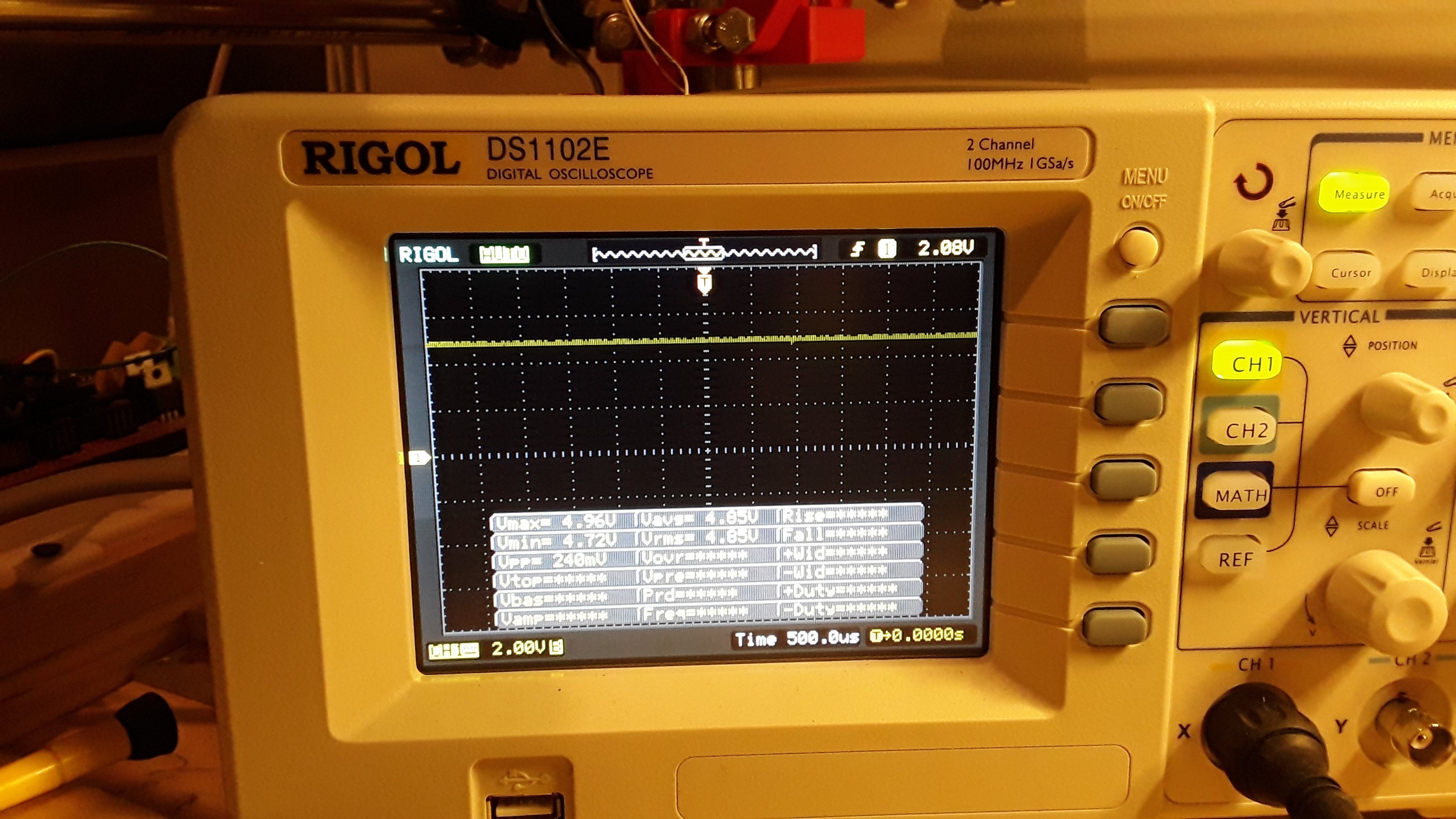
Note that with PWM (Pulse Width Modulation) it is the DUTY CYCLE (ratio of time ON/HIGH to total period) that is changing – it’s not a constant DC level – and the multimeter is only averaging the signal. This particular signal shown is switching between +5 volts and 0 volts (these are the “TTL” spec levels)… and there is a +12 volts version (which duty cycles exactly the same way) and is often used for fan control, i.e. D9 on RAMPS. What Jeff is warning against is… if the TTL PWM input to the laser control board isn’t protected (“tolerant”), applying a +12v PWM could possibly blow it out.
I don’t know which pins are PWM-capable on Archim boards but they will operate as described above with the appropriate gcode command.
– David
2 Likes