So I assumed that the Archim1 board would have GPIO pins similar to a pi, and that I could trigger some relays in order to activate my plasma torch, or my router/vacuum.
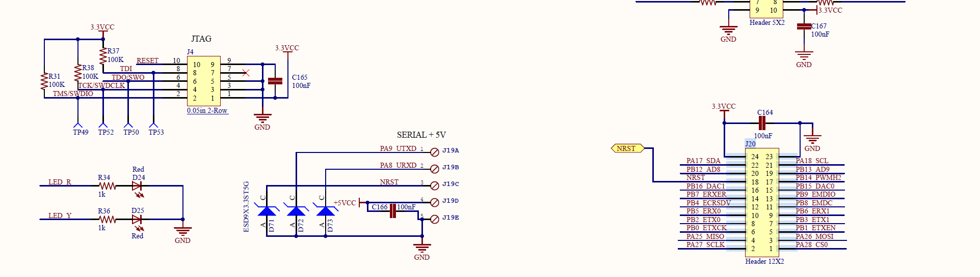
Doing some digging, and it seems like this might not be the case? I don’t see any lines in the firmware that allow me to define the pins. As well as I’m not sure if any of the pins can even be used for what I want. (J20 is the GPIO header - the pins seem mostly for different arduino communication protocols.)
So that makes me think that I will need to get creative. The relays require 5.5v, 3.3v, ground, and an activation pin for each relay.
So I’m thinking I can source 5.5 and ground from the SERIAL connection. 3.3v from J20 pin 24…the tricky part possibly being the trigger pins. I was thinking the ground pins from fan0 and fan1 or heater0 and heater1. But I’m not sure if those will work? I’m not well versed enough to see if these are in the firmware and able to be commanded.
Yep. I have the Archim 2.0 and the pinout is the same.I use fan0 to do my relay, an IOT power block and fan1 to run my case fan. M106 P0 and M107 P0 to stop.
Fan1 and Fan0 are source voltage, 12-24V though. You can change what pin is used for the fans though, in the pins file. Then M106 will toggle that pin instead, which is probably 5V. You need to be careful that it isn’t drawing current though. Those J20 pins can probably only source 20mA max. It is fine for a digital signal, but not for powering a relay.
Ah, so just using the fan power to trigger a relay instead of going the digital route. I guess I was trying to over complicate it. Less than ideal for my current situation, as I have a stack of 5v relays and no 12v relays.
IIRC, the relay that Marion has is the IoT relay I posted a while ago from amazon. It takes almost anything as input, so a fan port or a digital output works fine with it.
If you have one of these common relay boards that run off of 5V, you just need to change the fan pin to one of the aux pins, and then use the fan commands with it.
Now I just have to figure out how to implement that. I’ve barely dabbled in arduino stuff, so defining the pins and triggering them is not a skillset I have acquired yet.
Ok…so I hooked everything up and tried to make a simple oval and create the gcode with estlcam. I set the plasma activation along with a 2 second pause to be:
M42 M3 P70
G04 P2000
But no luck. I used the J20 connector pin22 (PA17 aka digital pin 70) Does this code look correct?
Interestingly enough, during my troubleshooting I found that if I tried to print my file, the contents of the file would be NULL after returning the SD card to my computer. I’m not sure if this is because of the file freezing and failing? (EDIT: I’m guessing that M30 code has something to do with the file being emptied?)
I did however take the same activation and dwell codes and paste them into the crown test file and the movements ran as expected. (But no activation of the relay.)
Thoughts?
Oval code:
;Project OVAL
;Created by Estlcam version 11 build 11.221
;Machining time about 00:08:36 hours
This thread has me very hopeful, I’m by no means versed in any of this so everything is new to me but I’m hoping I can set up my Archim v1 to turn on a relay (to power my shop vac) and then turn send a signal to a speed control for my needle cutter. After reading through this thread its got me hopeful that I won’t have to do too much or any updates to the firmware? but was wondering if the above solution could be adapted to control the speed control at the very least? if I understand that last message @Crash85 “S0” would basically be full power and the larger the number (up to 255) reduces the output?