Hi everybody,
I am trying to build a somehow well documented (with good tutorial and a custom and customizable arduino program available) digital indexing head:
http://www.liming.org/millindex/
It is both praised and blamed by those who tried to build it.
The project describes a cheap, autonomous, indexing head driven by an Arduino Uno and deviced with a simple LCD/keyboard shield and controlling a stepper motor through a stepper dirver. It can select in service several modes: indexing where you define nr. of circle divisions and stepthrough them, angle mode jog where you can define an angle as base unit for jogging, step mode jog where you can define a number of steps as base unit for jogging and continuous rotation whose speed can be altered -all working CW and CCW.
Gary Liming is activating in Hobby machinist forum, with members having mostly workshop formation (like me), and with poor knowledge in programming, arduino, drivers subltilities a.s.o.
For those for which worked, worked easily and cheaply; for those for which it didn’t, nobody offered a diagnostic and a clue, many blaming author. This was long time ago, as article appeared in 2013.
I have the luck (I presume) that I have encountered somehow identical issues when an Arduino Mega based board could not follow instructions in Repetier (at least this is what I remember) Then, looking for clues, I found out that some Mainboards have larger tresholds for things like signal duration, pause duration (in ms) then those defined in standard Marlin. I also found that some chinese stepper driver"s optocouplers are slower than Arduino various software based on genuine components could handle.
So my guess is that it is an identical issue in indexer’s case. Of course it doesn’t make me me smarter so I’m sure I cannot correct the Arduino code. All I can plan to do is trying to swap various stepper drivers to prove miself that it is not a wiring error (generated by me or the type of LCD/keypad shield (a lot of clones presumed identical Made in China -of which I have one), or find a working combination, controller-shield-driver-stepper.
What I’m asking you to help with is identifying in Arduino code and changing those parameters for not-so-performant components/boards.
Another program related issue for me would be increasing stepper-s base speed. Original sketch was written for an indexing head, where speed is not a target.
Myfordboy, in one of his videos presented the advantages of the build: an autonomous digital control box which you could swap from stepper-to-stepper; to control either a lathe’s advance or a mill’s indexing head.
One of applications I have in mind is automatic feed/ variable speed advance on X on my mill’s table, where maximum speed should be higer than 0.2 screw turns per second.
So I ask those of you familiar with programming to help me making this work.
Currently I have made the test on “spider assembly” and all I can get is stepper braking/buzzing. Yes, I have tried also swapping wires from one coil of motor with no better results. In one variant of wiring I have obtained a stepper rotation (random, like 1 in 10 trials) so I consider this wiring to be correct, but something else is twisting my luck.
Please help me make it work.
I took a look at the code for your project. It’s not overly complex, but there are enough things that could go wrong that have nothing to do with the stepper driver/motor, that I would take a step back and get just the stepper motor working. I would purchase a common driver board like the A4988 and then directly wire up the stepper and the driver to the Uno using a tutorial like this one. And there are other tutorials. In addition, these tutorials will walk you through getting the v-ref setup. At the point you have your stepper working, you will 1) know your wiring is correct, and 2) have some simple sample code you can compare and contract to your project code. BTW: The movement code in your project is small…just this function:
void move_motor(unsigned long steps, int dir, int type)
{
  unsigned long i;

  if (type == movesteps)
    displayscreen(movesteps);
  if (type == moveangle)
    displayscreen(moveangle);
  for (i=0;i<steps;i++)
  {
    digitalWrite(motorDIRpin,dir);
    digitalWrite(motorSTEPpin,HIGH);   //pulse the motor
    delay(pulsewidth);
    digitalWrite(motorSTEPpin,LOW);
    if (type == movesteps)             // in this mode display progress
    {
      lcd.setCursor(10,1);
      lcd.print(i);
    }
    if (type == moveangle)             // in this mode display progress
    {
      lcd.setCursor(7,0);
      lcd.print(i);
    }
    delay(motorspeeddelay);            // wait betweeen pulses
  }
  return;
}
And half of this code is updating the LCD and not related to movement.
Thank you, Robert, for your advice!
The indexing head really looks like a promissing solution for my needs. It is simple and cheap in hardware and wiring and on pair in software. If lots of people succeeded with it I don’t see a reason why I shouldn’t reach the better end.
I’ll try the debugging solutions you mentioned. I mention that current stepper driver I have tried is the one from tutorial, that is TB6560 but I also have various steppers both Nema 17 and Nema 23 and corresponding drivers to test.
I have to confess that although not complex, the code looks like a lemon byte for me. I’ll try to take it with some sugar…
Maybe we can handle this in a bit different way. Save a copy of your original code, then make the following changes:
On line 73, change:
#define pulsewidth     2    // length of time for one step pulse
to:
#define pulsewidth     2000    // length of time for one step pulse
At line 149, you will see this:
displayscreen(cur_mode); // put up initial menu screen
And it should become this:
  displayscreen(cur_mode);           // put up initial menu screen
  motorspeeddelay = 1;
  while (true)
  {
    move_motor(3200, CW, movesteps);
    delay(1000);
  }
And finally, change this line:
delay(motorspeeddelay);
to:
delayMicroseconds(pulsewidth);
+++
These changes do two things. First they change how the pulse width is measured from milliseconds to microseconds. A microsecond is 1/1000th of a millisecond. I don’t really think the pulse width is the issue, but you indicated it might be in your original question. I noticed in the tutorial they were setting the pulse width to 500 microseconds, so you can try setting different values from 250 up to 4000 to see if something works.
The second thing this code does is bypass all the gear ratios and button logic and other code and, directly moves the stepper. The stepper will rotate for 3200 steps and then pause for one second and then do it again. How many rotations that adds up to will depend on how the microstepping is set on the stepper driver. With a 1.8 degree stepper and microstepping set to 16, you will get one rotation out of 3200 steps.
Note there is a potential bug in the movement code that would result in the behavior you describe. If the variable ‘motorspeeddelay’ has it’s default value of 0 when the movement code is called, the pulse pin for the stepper motor never really goes low. The above code will address that problem enough to troubleshoot the stepper motor code.
That seems like a pretty neat project. It reminds me of my cam slider software. This runs on an ESP32, and I bought a board from bart dring on tindie that connects up to some drv8825s. I found a neat library to quickly make simple web controls, which would be great for this project, IMO. It will really make the hardware simpler if you don’t need to make a controller too.
Feel free to ignore me though. I don’t want to lead you far away if you are close to getting your solution working.
Hello and thanks both for applied answers.
I will try the to make reccomended changes to the code and see how they work. The weekend is the only time I can do these and I’ll give feedback for sure.
Jeff, I have often met you on several threads, proposing solutions targeted to author’s defined problems. You are really a passionate fellow and somebody that makes things rocketing (not to mention V1pi which is ongoing on one of my monster -projects which I don’t know when will be finished)! Thank you! I am really interested in various aproaches close applied on the purpose, which are simpler and easier. I have a lot of components remaining from old projects or for unnominated future ones. Though, for the moment, being involved in a different project I won’t insist on it. Just tinker the current indexer on the test-board and put it in a box for later finalizing. But I will look for your suggestion.
As an aside, I have a small Sieg mill (labeled Bernardo- European company) which I consider very useful. I have CNC-ed it since -I think- 2015, with LinuxCNC on top and… that was all. I have regularly very small projects and work only with chunks of metal and usual cheap profiles I can find around -at least for now (here where I live a developed market for raw materials dedicated to hobbysts is not really existing). So I cannot develop too much CAD/CAM designs. I adjust my projects on-the-fly, based on what I have available. But I think to automatising certain aspects of manual aided machining (MAM  ) for faster and easier handling of jobs.
Hi,
Problem of motor not spinning solved. I can’t believe I’ve made a noob mistake with such a simple wiring diagram. Actually I have swapped enable with clock from LCD to stepper. Reason might be I have used wires with colored strips.They are harder to follow than uniform color wires. I have checked them about 8 times last weekend and made the same mistake each time…
Anyway, thank you Robert for your advice, I have to test your mod of the code; when you’r relaxed makes more fun experimenting.
For the other issue - increasing maximum speed; how can I get to it?
If it is working, you don’t need to run my mod. The mod was only for troubleshooting. As for increasing the speed, it should be easy. Since I don’t have the hardware, it may take a bit of back and forth. I feel a bit uncomfortable sharing copies of code where I’m unsure of the license on a public forum, so PM me an email address, and we can handle it privately.
A short, first, feedback;
I have finalized the controller (the compact version). Attached some pictures. Sorry for quality; they were made with my phone and, apart from poor light , was tricky the balance between LCD contrast (which is very bright overall) and general image contrast.
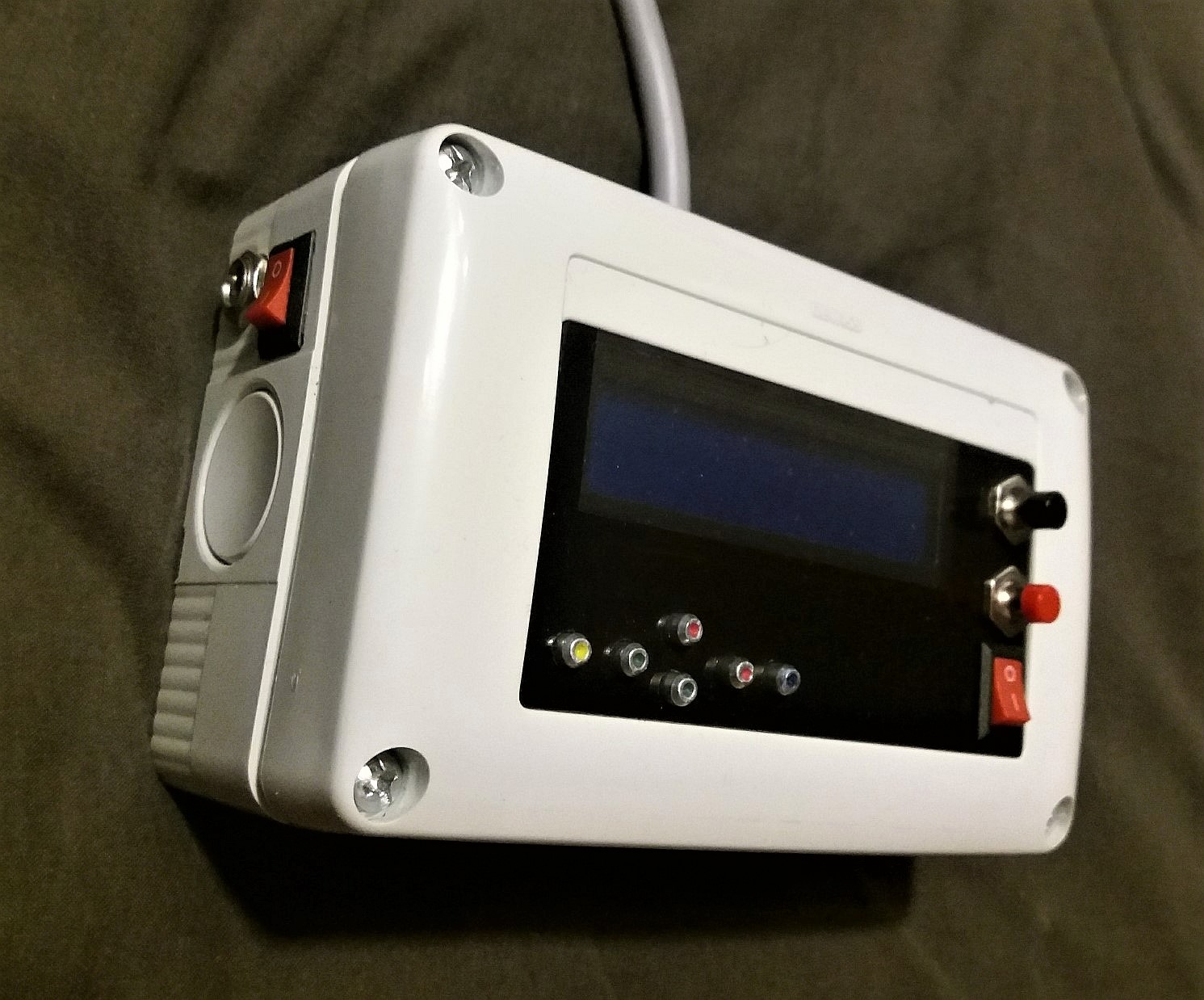
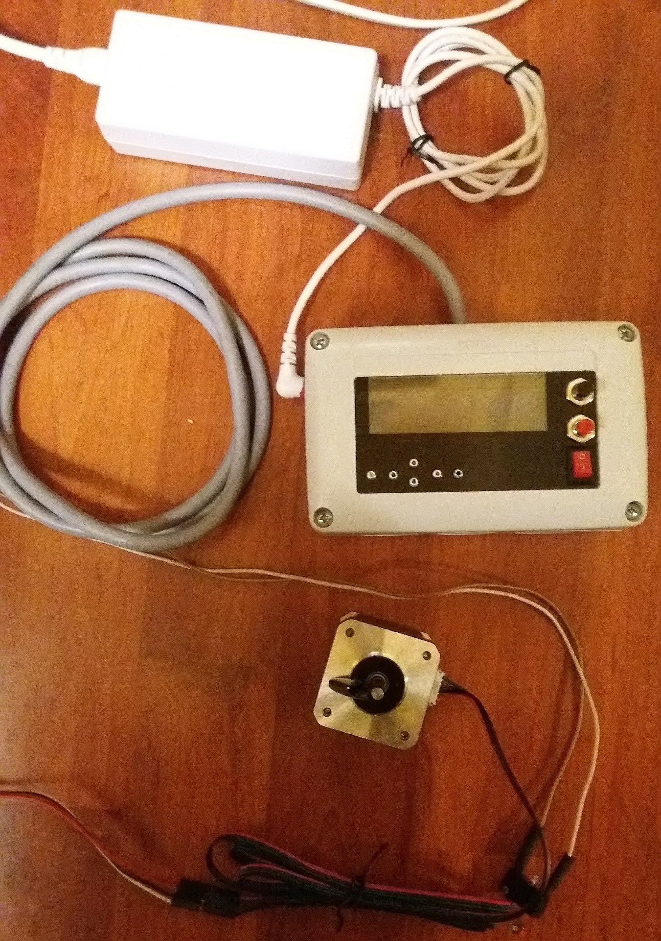
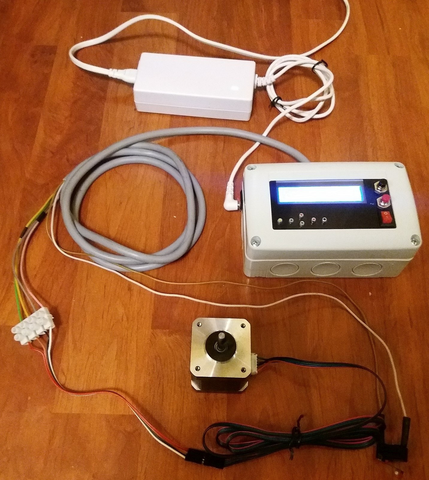
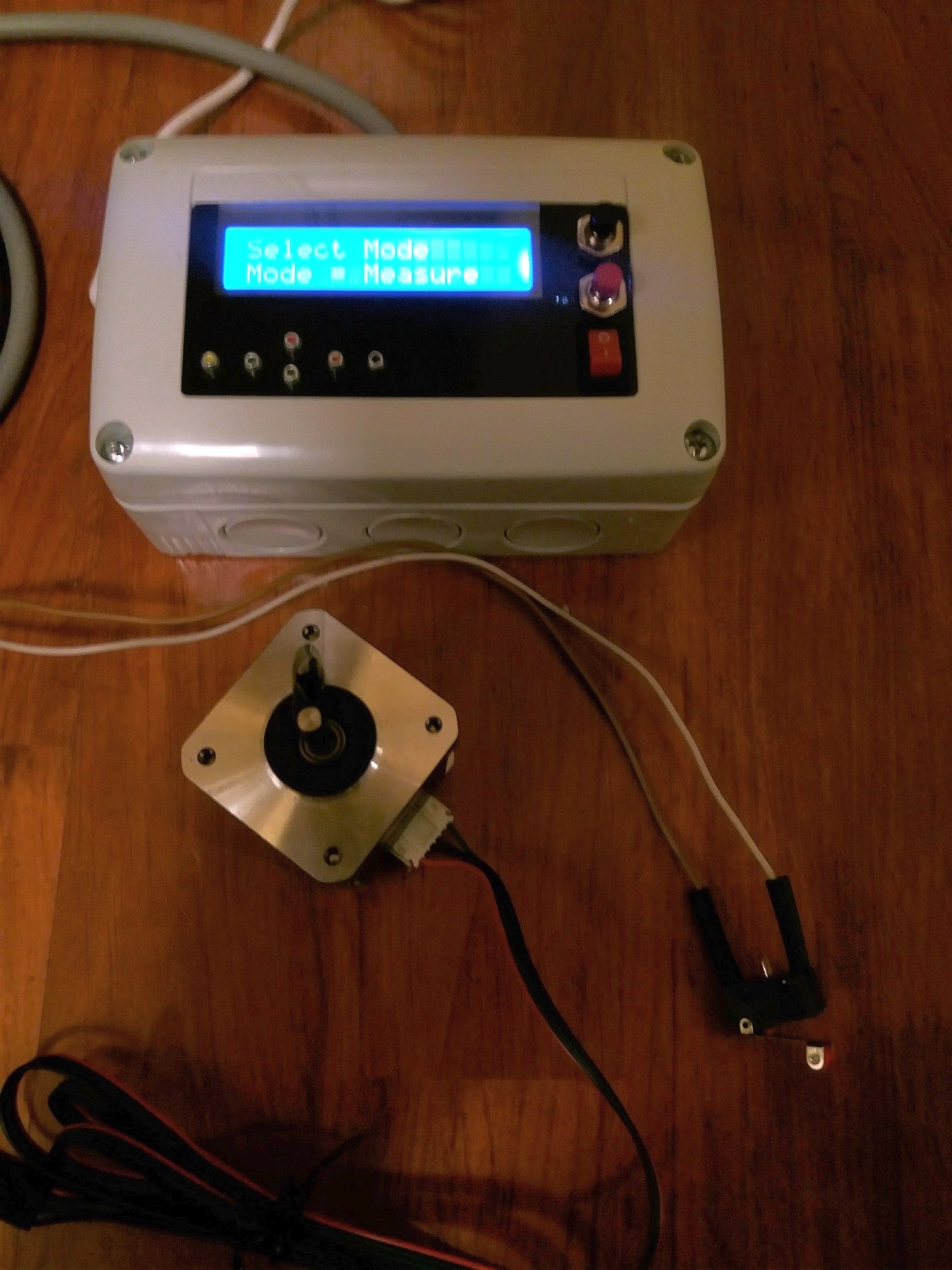
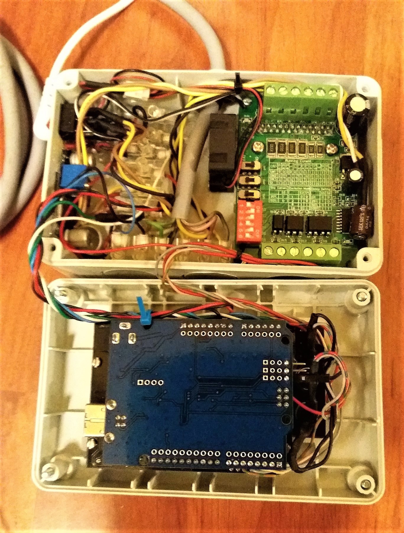
The case (an on-wall 2-power-plug case) houses the LCD shield/Arduino Uno assembly, TB6560 stepper driver - which i consider much more customizable with its current decay function and other extra options , a DC-DC converter which keeps voltage for Arduino at 11.3V whatever power source, cooler fan, switches and wire connectors.
The current trial that shares the same connection cable for stepper and limit switch was busted by random disables in operation (well, I knew it but I was hoping…)
So the next option will be a separate printer style USB shielded cable for limit switch connection. I will have advantage of using short arduino-furniture cables for fixed mounting of unit and long printer cables for remote operation. They also provide a quite safe connection at both ends.
The main improvement is in software.
Robert Bunney -as he offered - made a lot of improvements of the code.
Garry Liming -which I have contacted meanwhile - did a great job already . It’s the reason why I was attracted by this setup. But Gary was focused on Indexer application; though he mentioned the use in many other purposes.
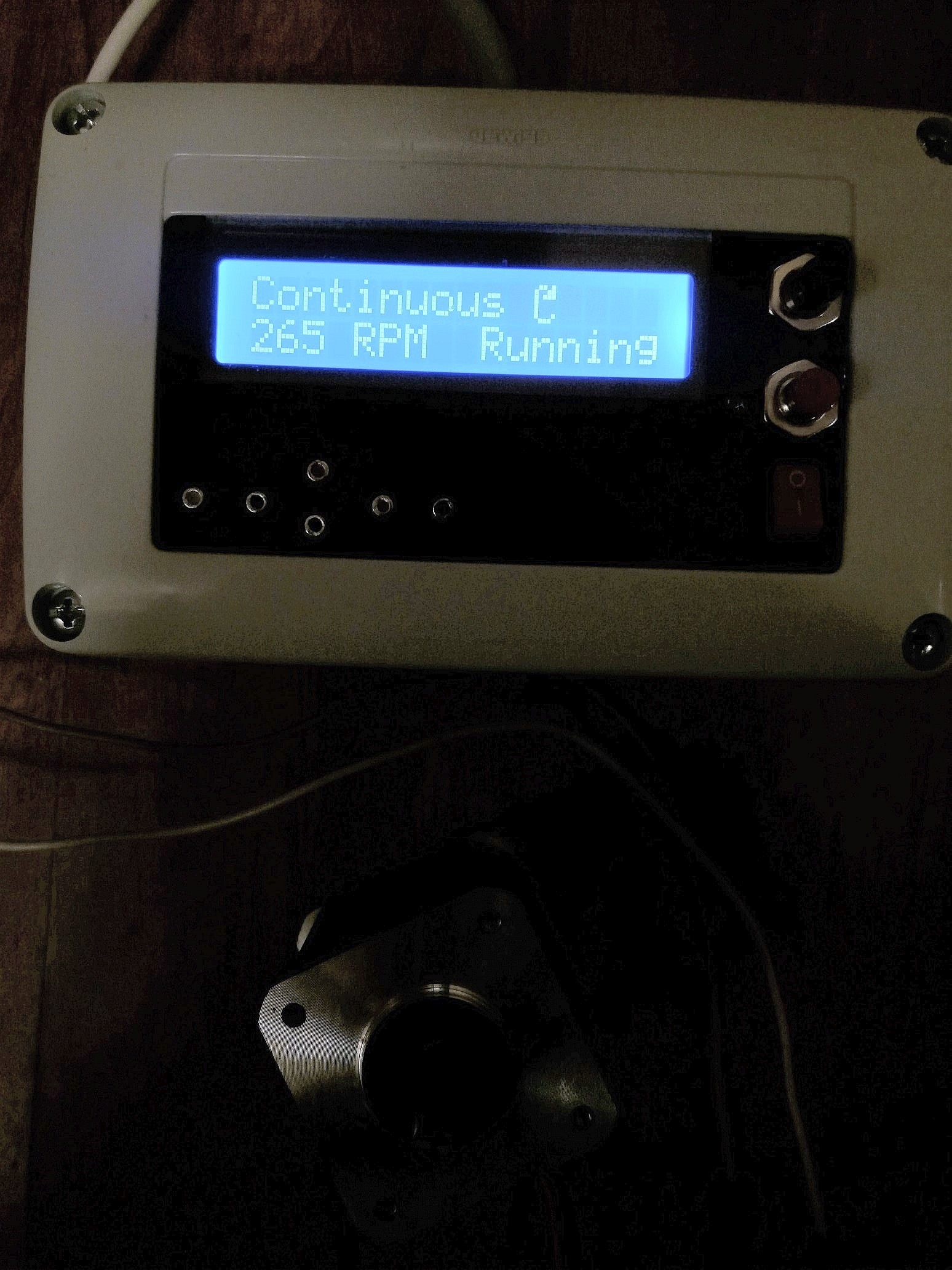
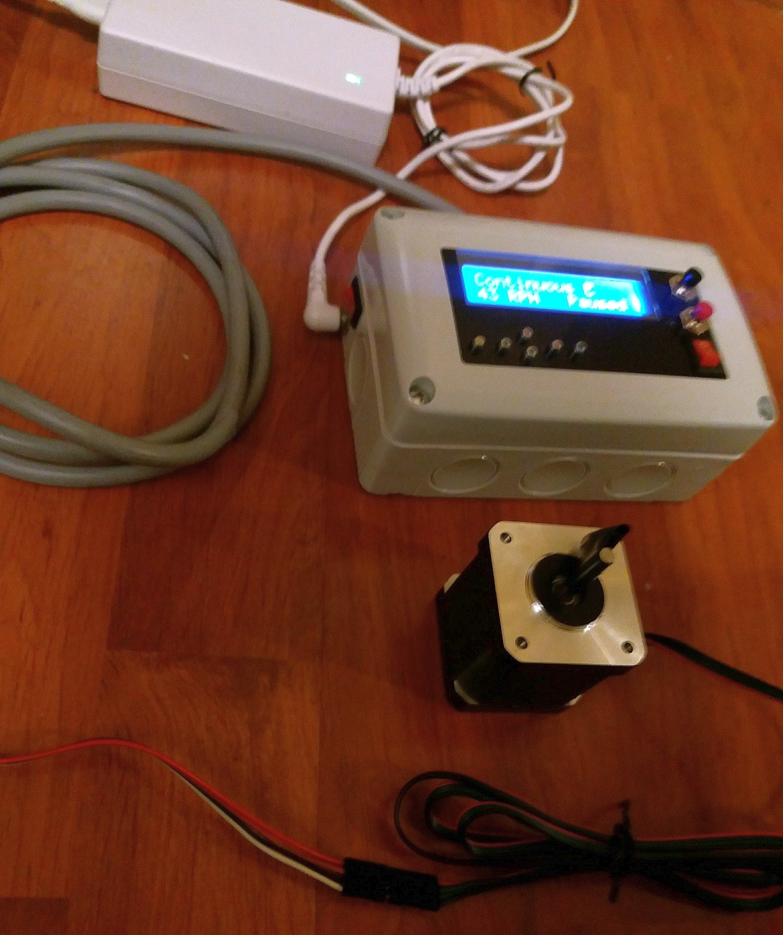
My main intended use is a power-feed for my mill; but I had in mind many other applications. So did Robert also; so the program received wider range of features or capable parameters.
This required some major changes. Main mode considered is RUN mode (I have considered for power-feed). It is featured now with acceleration which aids it cope with higher loads. Speed range starts from 1 RPH (per hour) up-to about 900 RPM (unloaded - reached). I count on 500 RPM loaded. This mode has some additional features added - micro-step change in menu with saving to memory (this provides a smoother movement in the range of RPH. Of course, maximum capable RPM decreases with micro-step increase. You have in addition to switch stepper driver to set micro-step (this should be known, I guess). The large range of RPM allows a lot of applications: like lathe lead-screw, workshop power-feeds, camera control, 4th non-CNC axis in a GRBL router/mill, house intelligent/remote controllers…
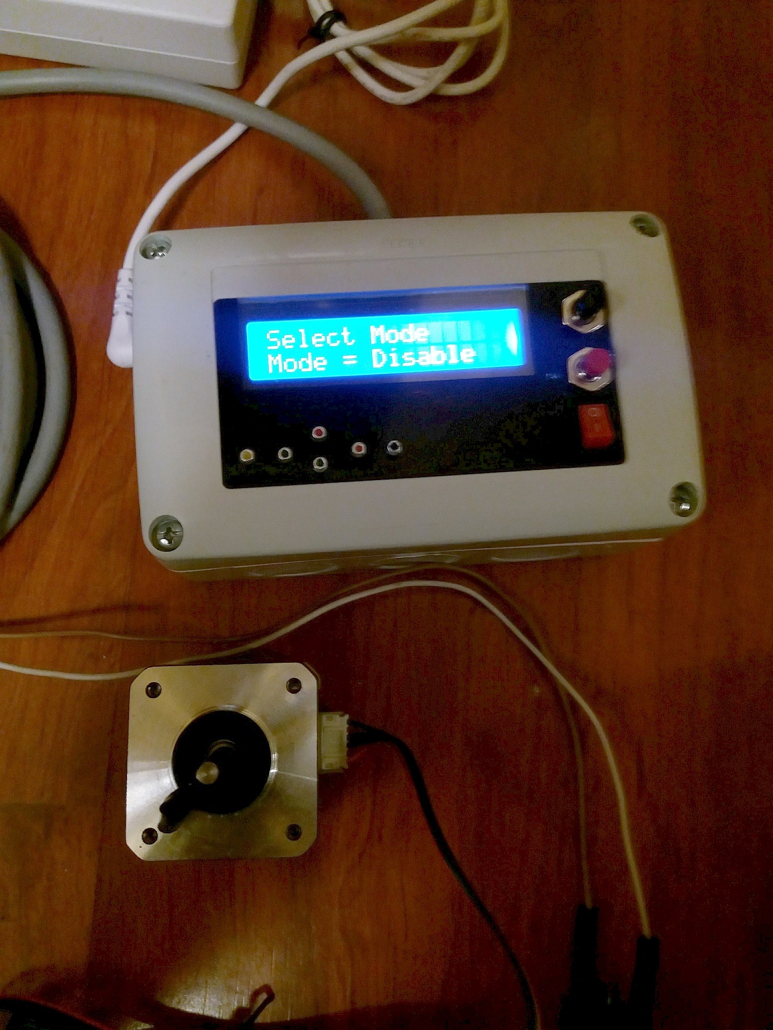
Run mode is additionally featured with failsafe (limit switch), emergency stop, software motor disable for alternating power-and-manual machining (stepper, in original, code was kept under power -for holding current position). It requires tuning for initial install according main use and parameters ca be modified in .ide file.
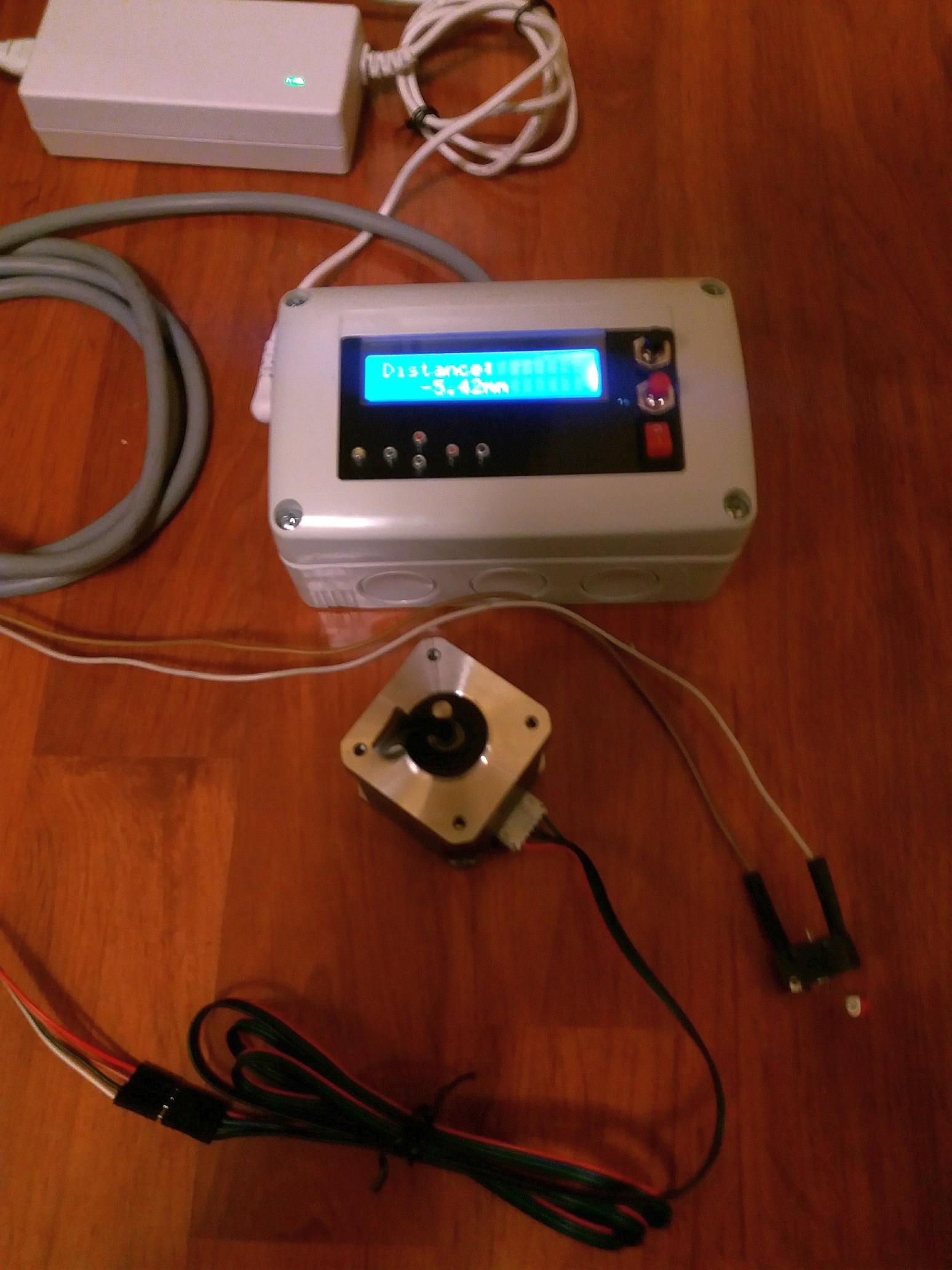
Another new mode is Measure. The display shows table movement in mm (inches), it is set to 0.00 when entering this mode and displays both negative and positive values. up/down buttons make long steps, left/right buttons make short (adjust) steps. Step values can be adjusted when uploading program.
This mode is particularly useful with repetitive patterns machining; mounting holes drilling - replicating an assembly drawing and so on.
That-s all for the moment, but I will return with additional details.