Tom Sanladerer did a series, https://youtu.be/52FrJzMWbs4, his build series has helpful info. Unfortunately, the last video ends with some unnecessary drama. Shame, because I usually like and learn a bunch from Tom’s content.
This is the old one, no? So the trucks are different and id imagine the core is as well
You must be putting a lot of force on them. The endmill only gets a couple pounds force right at the tip. You leaning all your weight on it is not a valid test. Push the endmill with your pinky finger tip for a better test. (welcome to the secret, non-steel milling takes very little force).
There is a note in the instructions about this. Take the clamps off, tubes out. Then tighten the clamps, reinstall them on the core, loosen them up, put the tubes back, now adjust the tension.
?? You might want to check your rail diameter or your printer’s calibration, these are interference fit. Judging by your previous core clamp issue you might need to look into your printer, or rails.
So you clamped down so hard you squished the bearings into the printed parts?? Take a closer look and please test your rails diameter.
What you are describing is not common so to reiterate your printer is either WAY off, or your rails are more than 0.4mm off.
Changed the title.
Yeah that makes sense
This is honestly probably user error, 2 of the trucks are perfect and 2 have some wiggle on the rail.
On all the core parts I just snugged the locknut up to the print so you can’t jiggle the bolt up and down anymore but I didn’t go further than that. Really confused as to where the marks are coming from they look almost like skid marks on the road. I’m not using stainless steel if that explains anything.
Measured the rails to be 25.44mm, I’m using the J 25 .4mm printed parts.
The clamps are designed to go further than that there is a 2mm gap around the bearing that can be closed.
Same on the trucks except I did design them to be tighter from the start.
Should just be the zinc wearing in. If you are using galvanized conduit.
Skid marks! That’s hysterical. It does kinda look like that.
First of all, a 10mm deep cut is really deep and really pushing things a bit hard. This CNC is made out of PLA, don’t forget.
Secondly, your end mill is long and thin. It is going to flex and gouge instead of cutting smooth. There will be a sickening amount of shudder and vibration, I think, and you are going to break something: it or the MPCNC.
Thirdly, check how rigid and tight everything is, including the router mount.
If you’re going to use a long skinny end mill like that, I wouldn’t be doing any more than 3 mm depth of cut. And perhaps a feed rate in the vicinity of 500mm per minute.
He has got a DOC of 1mm (which is really, really low) and got to 10mm before it happened.
2 Likes
Just finished fully disassembling my z / core. For the bolts that go through the core and into the core clamps, is the tolerance tight enough by design that the bolts cannot simply be pushed into the holes and instead have to be screwed in as if it was threaded? Mine was the latter and it seems as if that could contribute to making it harder to snug up the nut to eliminate slop.
Using non-stainless steel tube/pipe
yes
Should make no difference. You can thread the tension bolt in no nut and keep turning until it turns more freely, or you can just tighten the nut side. You have 200X the force required to move the plastic it does not take much.
Took the entire core off (which meant going through the agonizing process of pulling all the wiring back through the cable chain), reprinted the core clamps, put the new core clamps on, and put the core back on. It is many times more snug now. Almost rock solid. Just an ever so slight amount of wiggle if I pull from the bottom of the core.
The question is - how tight is too tight? I have the “Gantry Rail Tension Bolts” from the assembly instructions in with no nuts on them. The 2 bearings furthest away from where the y and x gantries meet (the bearings at either edge of the core) grip enough that if I turn the bearing by hand, it drags the core along that tube. Meanwhile the two inner bearings don’t contact the gantry tubes at all it seems. Am I still doing something wrong?
1 Like
Did you go through the steps of squaring the trucks and everything?
Just take another look through the instructions and make sure you get it as good as you can. There can be issues with your prints but is suspect even if that is the case working through the setup will get every bearing touching at all times.
1 Like
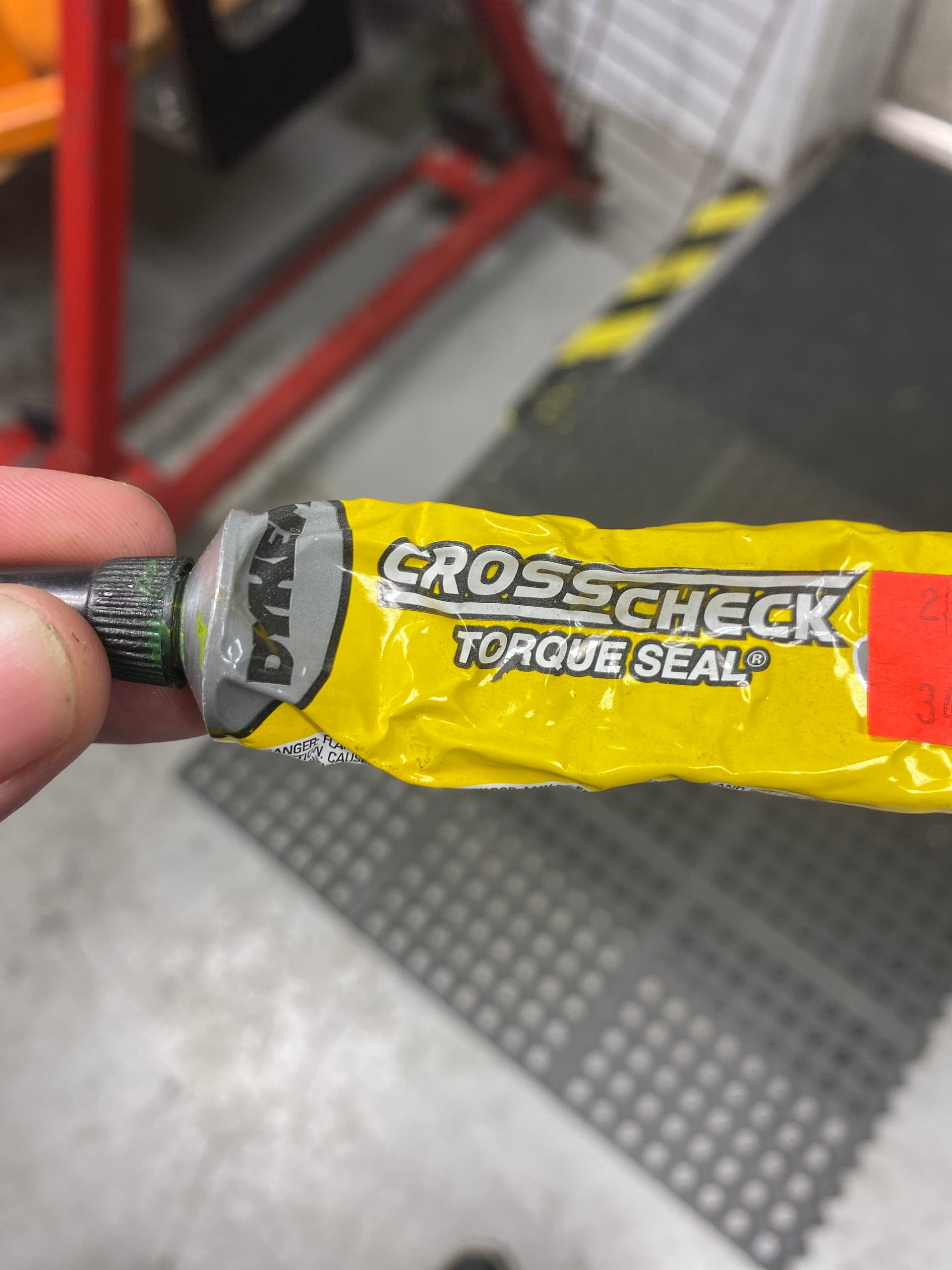
I know you said you confirmed the grub screws but some of this or some nail polish can help give you a quick visual of things staying as they should. I am super noob but just wanted to add this.
1 Like
Oh, I thought it was supposed to make proper contact before squaring the trucks. Here’s a quick vid of where I’m at now:
https://youtu.be/vmCiM5pNzo0
Squared the trucks, put the core back on, clamped it down. It seems much better than last time, and all 4 vertical bearings in the core clamps appear to make contact with the gantry rails now, but it seems like there’s still a slight bit of wiggle.

If all bearings are making contact and there is no clicking then it is just the large build volume and the rails bending. Both your axis are 3’ My work area is about 13"x15" and significantly more rigid.
The load at the tip of the end mill should be much smaller than your hand. Time to give it a shot and do some testing.
Do I need to change any estlcam settings to use the single flute bit?
1 Like