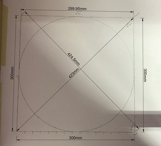
I have finally got everything running smoothly and the time has come to calibrate the machine. I ran a gcode to make a 300mm x 300mm (my machine can jog up to 550mm x 550mm but didn’t have such a big paper to print on). The square came out OK but I couldn’t understand how to calibrate from the instruction in the auto square part. For that reason, I am including the square that the machine produced (printed counter clockwise):
Can you please let me know the offsets that I need to set?
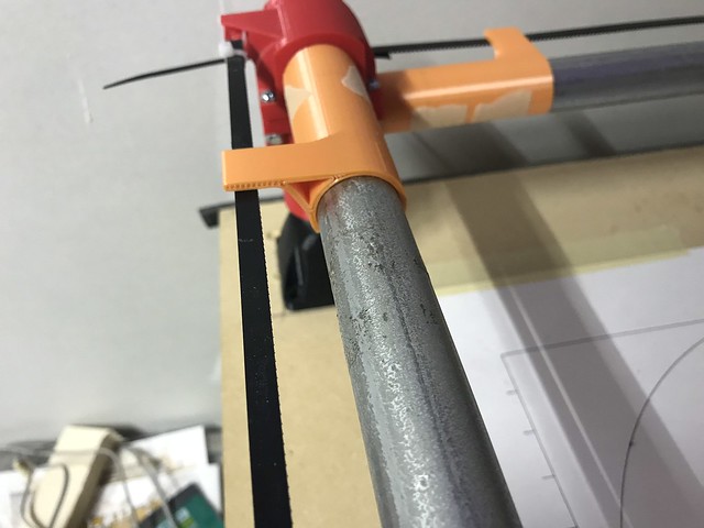
Just an FYI, the end stop that goes onto the belt was not working properly for me (too loose so that had a flop and was not getting consistent result). For that reason, I designed a stop that should help me get consistent stopping distance:
Thanks Ryan. Offsets limited to just X1 & Y1 makes sense; I couldn’t figure out how I can set the offsets for X2 & Y2.
Just to make things easier, should I just switch the wiring (making X2 -> X1 and X1 -> X2 and same with Y) to make setting offset easier? From the look of it, it seems like most time, you need to offset the right hand side.