Because why not one more project?

So aesthetics for the endstops…Tough to figure something out that won’t look terrible, without re-printing parts. Well, that might end up being the solution.

I have most of it together now. No mounting solution for the control board yet though, and still batting around ideas for extruder and hotend mounting. Something like a Mk8 extruder and hotend combo is tempting, as it’s pretty much a done deal, but this was supposed to use up leftover parts, not have me buying more. I’ve already bent that rule a little because I’d forgotten that I’d used some parts already. This was supposed to be something to fill a gap while waiting for some stuff for my panelsaw, which is to help build the LR2. Not like I need another 3D printer, really.

Pictures, just because.


Mostly assembled. I did install the limit switches for X and Y after this, and the PSU on the right hand side.


Drag chains, because wires unplugging themselves is annoying. This mount clips onto the chain link and holds it to the back of the X motor. Gravity and the wires keep it in place on the motor, a zip tie can be added if need be. I needed less than 1/3 of the drag chain I had, so one of the end mounts is bolted to the Y frame, and the detached link clips into this.


Here’s the other mount clip. The printed part clips onto the link again and will be mounted to the floor piece. There’s enough room for the 10mm drag chain to make a 180° bend under the Y plate.

The remaining section of drag chain will go to the hot end for fan, heater and thermistor wires. Maybe a Z probe, if I decide to use it.

The more I think about it, the more I think the Z probe is the answer. The dual stop Z would be cool, but the parts aren’t designed for it, and I’d rather that they didn’t look tacked on. I may retrofit optical stops for X/Y though. Just have to make a screw head cover flag, and an adapter for the optical mount.

Next though is a Jhead mount for the carriage.

4 Likes

Ok, I lied.

Was working on a Jhead mount and kept drawing it in mirror image to what I want last night, so I went to bed.

After work today, just kind of puttered around.

The Jhead that I had wasn’t a Bowden mount… the others that I have direct mounted were, and I used the threads for the tube mount to hold them.

Bollocks! So I got out an 11/64" drill bit, and a 1/8" NPT tap, and it’s a Bowden mount now. I used one of the NPT tube fittings from the Jheads that I direct mounted.


No jhead mount, but it’s hanging in there!

I used the extruder strap to mount the extruder to the top of the XZ frame. Drilled holes 64mm apart and strapped it down.


Ok, this I still ugly, I haven’t got all the wires run yet, still need stops, thermistors, fans and bed heat at least. I do have all the motors done.

Mounted the board on standoffs but could have screwed it directly down, since there is a small pocket under everything but the screw locations. Used the standoffs because I had them and airflow is good.

Spent the rest of the evening mucking with Marlin. I saw in the configuration_adv.h a parameter to enable G34, which does exactly what I want, so I mucked with that. I’ll also try bilinear mesh level, but might as well start with things as level as the hardware can get without help. Firmware flashed.


This positioning should allow for reasonable access to the filament, and the PTFE tube seems to reach the intended range of extruder motion without trouble.

So I need to get the heated bed installed, resolve a JHead mount not mirror imaged, with a probe mount, and part cooling fan.

Oh, and my multimeter won’t give me sensible ohm readings. I have a bunch of heater cartridges but can’t tell the 12V from the 24V. I expect 3.5-4 ohm or so from 12V and 15-16 ohm from the 24V ones. My meter is saying 0.2-0.3 for all of them. It’s also reading a 1% tolerance 100 ohm resistor as 36ish. Brand new battery. I think it’s bjorked. Still good for voltage.

I bolted on a 24V PSU, but also have a 12V one. Haven’t decided which I’ll use. 12V heated beds take so long to reach temperature though. On the other hand I have more spares of those. The only heat cartridge I know of 100% sure is 12V though, which may be the deciding factor, of I can’t find a better multimeter around here. (I must own at least a dozen.)

BowdenStrap
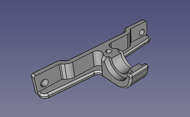
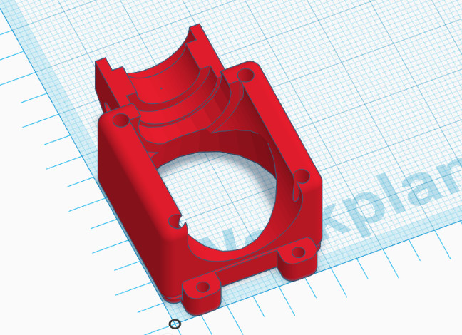
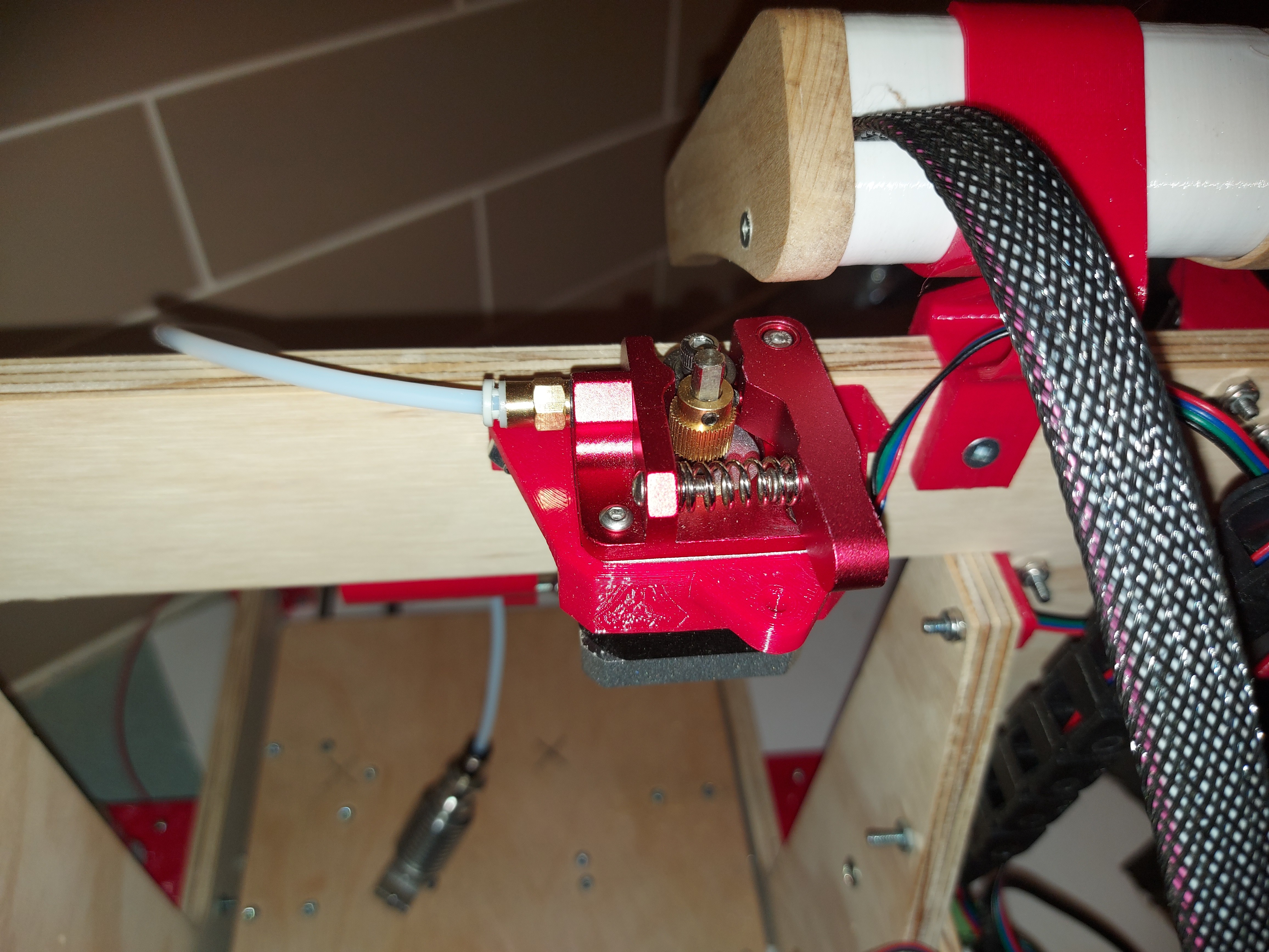
So this is my solution. It bolts onto the X carriage, and holds a J-Head, with room for a zip tie. The other half is a piece that I made for my other printers that clamps to the other side (with room for a zip tie) to hold a DC42 IR Z probe. The original holder for that slipped in between the shroud and the fan, which was great as far as it went, but I kept having to recalibrate every time something bumped the fan shroud, so I solved it by setting a fized distance from the sensor to the mounting groove on the Jhead, which I could do, since I was actually holding it in place to the extruder with the threads cut into the top for the Bowden fitting.

Fanshroud

I did that part a couple years ago in TinkerCAD, because it was good enough. I can see some things that were actually pretty bad in that model now, but it works, it prints well enough, and does the job I want it to.

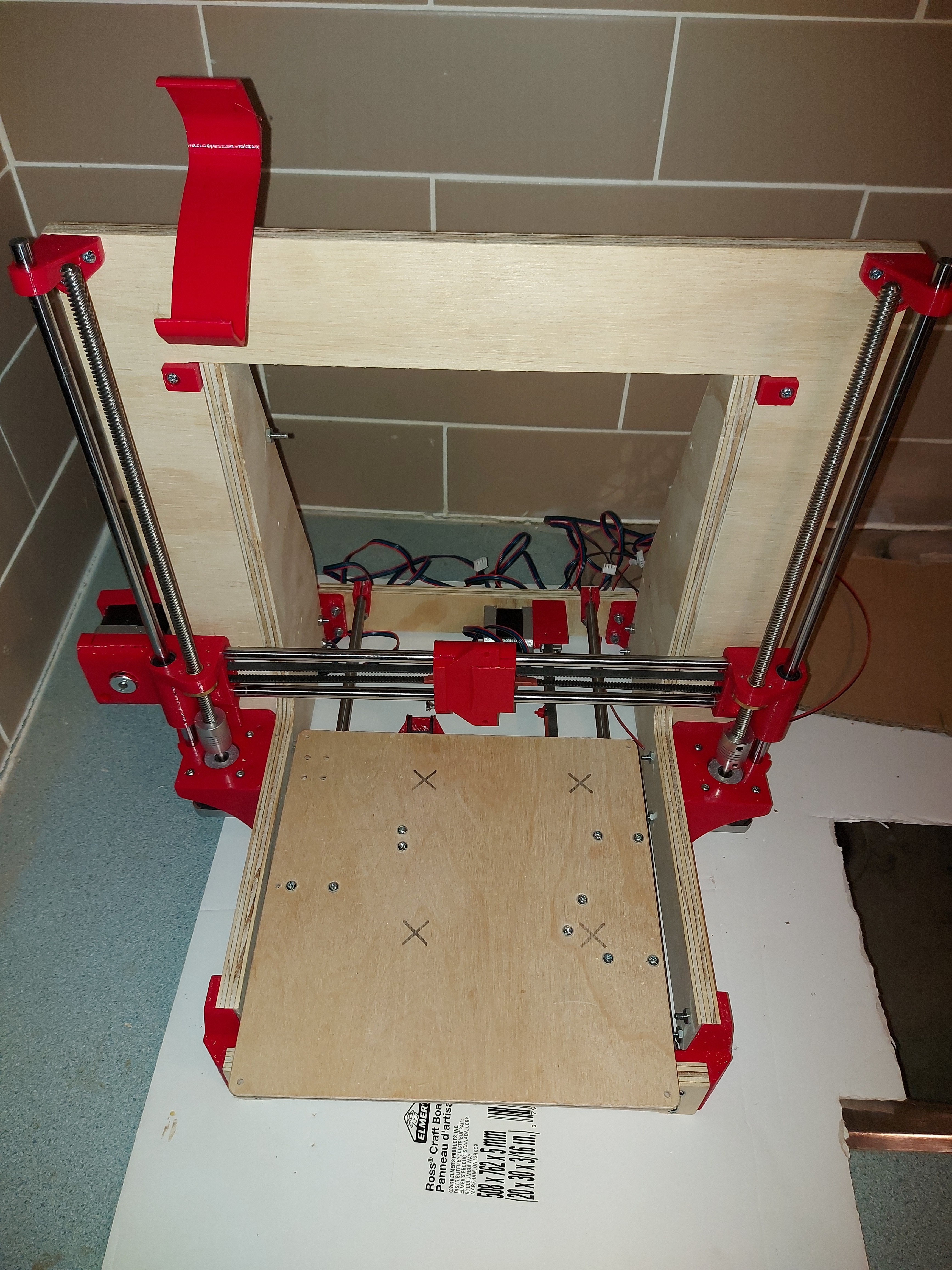
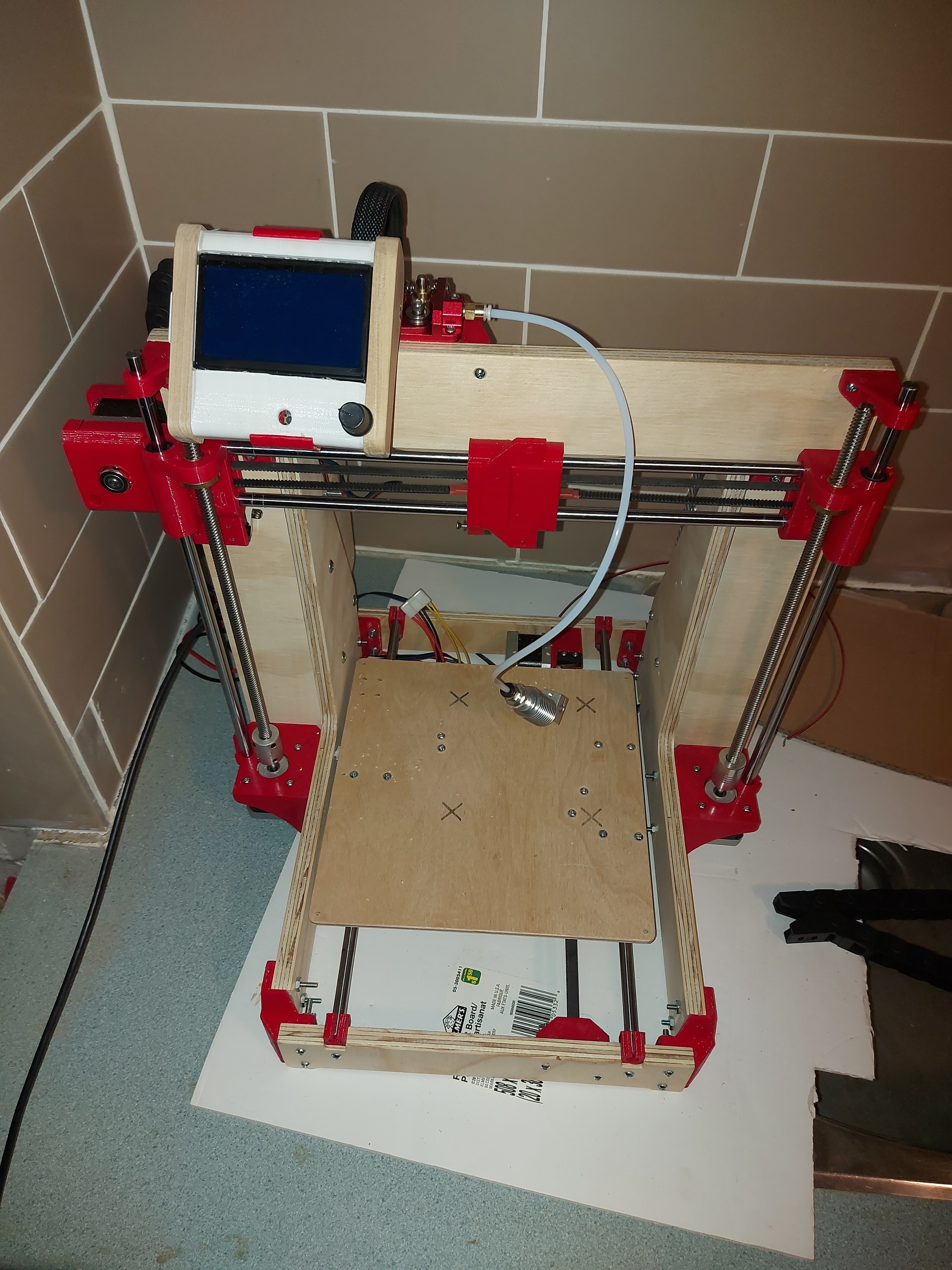
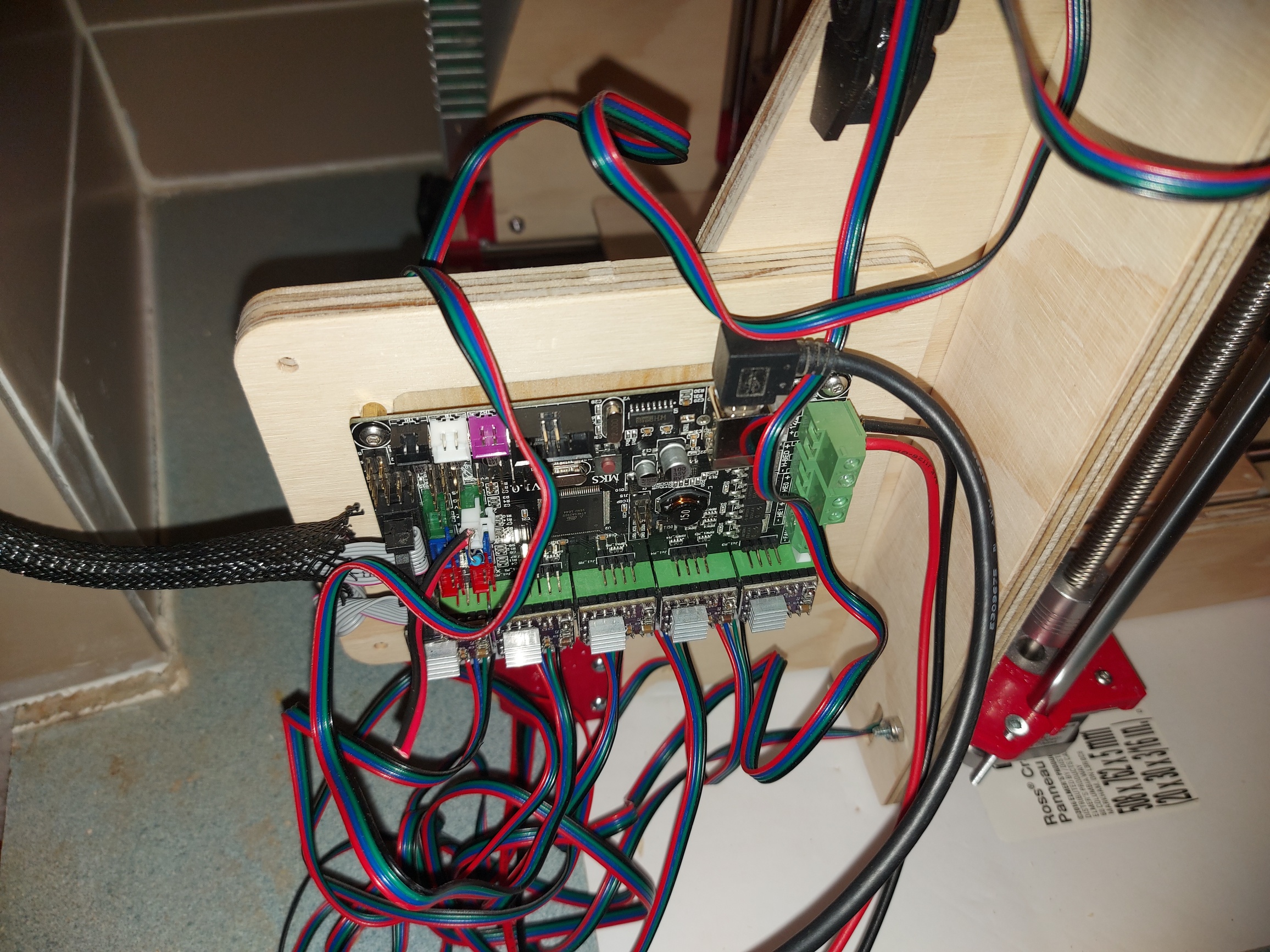
I put main power to the printer for the first time. Still no limit switches, but the firmware will allow me to move it without. X Y ad Z axes move as expected, including the dual Z driver, so I’m happy with that. Everything moves in the right direction too. Bonus, since the motors came with keyed connectors. Great for the MKS board, they match, but difficult to just swap the motor direction. If they were wrong, I’d have fixed it in firmware.

I don’t have a working 3cm fan for the hotend, so I’ll need one. Still need to figure out part cooling, too. The X carriage looks so empty without the bulk of the extruder there.

Progress has definitely slowed down, as I come to the end of what I can do with parts ready to hand. I bought a new multimeter today, so I could test the heater cartridges that I have. Of course this means that I’ll find one or more of the others that I own right away.

I need something to hold the IEC power plug. Deciding between milled and printed.

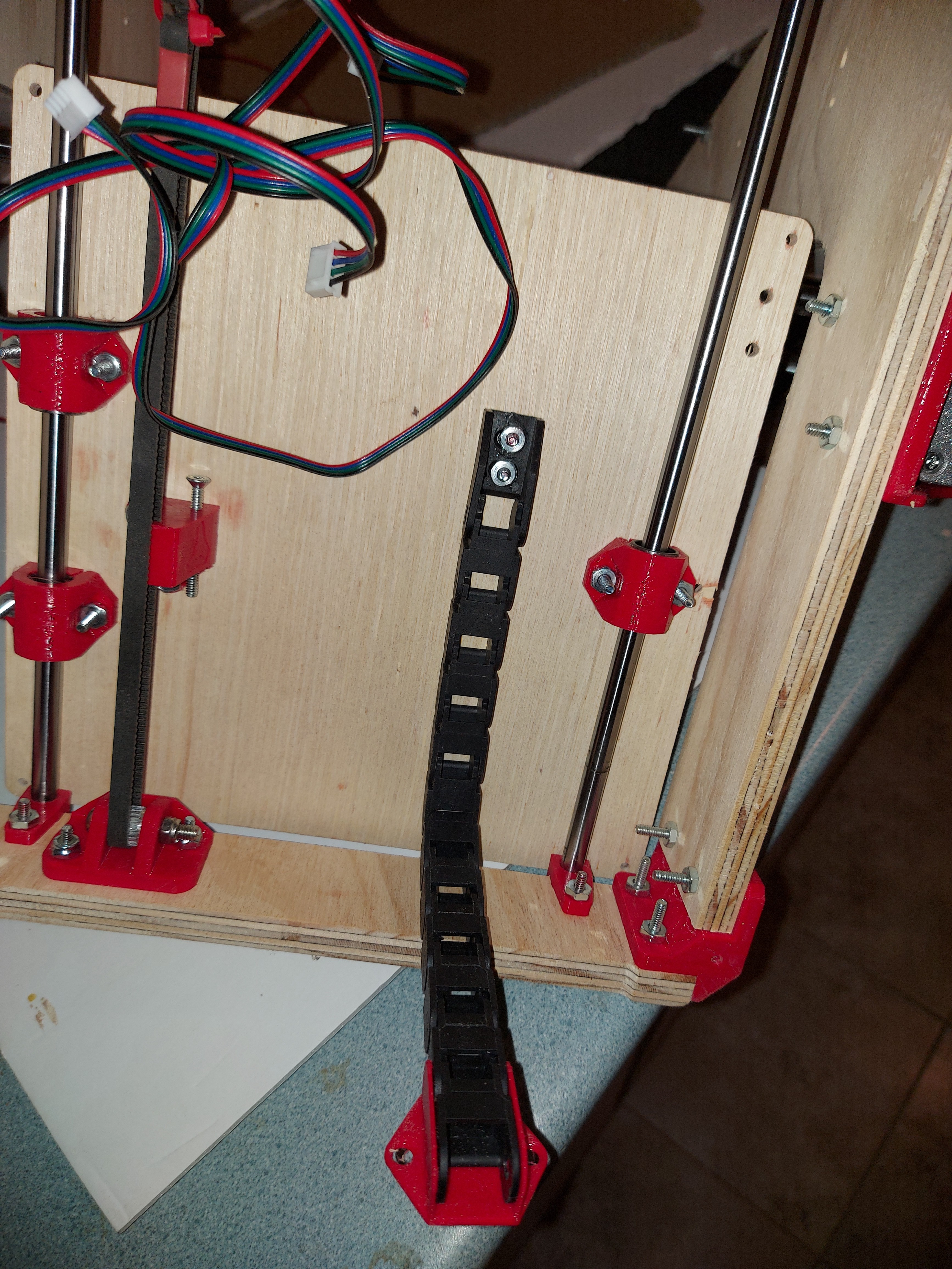
I still need to mount the heated bed, connect up the bed thermistor and power, decide if I want to use the offboard MOSFET to keep the power wires shorter, and loom all the wiring together.

Wiring harnesses are a weak point of mine. I always want to leave room for extra so that I can move stuff after, and it always bites me in the end, as I have extra wire with nowhere to put it. It seems though that every time I try to make things just the right length, I need to move something and really needed that extra 3" of wire to do it. I designed my current printer with a big empty space in one of the Z towers next to the control board, and it’s stuffed full of extra wire. Naturally, I haven’t needed a millimeter of the extra wire in it, but I don’t want to re-crimp all of the wire ends either.

This printer has no such space provided. Chances are pretty good that I won’t be replacing the control board in this printer, though there does exist the possibility that I’ll want to use a Duet, because I like them… But more likely this will end up being my son’s printer, and I’ll build myself a CoreXY.

I’m very impressed with how this printer has gone together, despite me doing stuff that is different from the original design at almost every turn. I’m using 1/2" plywood, not 3/8" as designed. 20T pulleys and idlers (Ok, I modified the parts to make that work, too.) and a control board that happened to be convenient to hand instead of the intended one. I lucked out in that my PSU mounts to the frame the same as the intended one though.

2 Likes

Been doing the mundane stuff. Running wires. Crimping (ugh.)

I need springs for the bed, I’m sure that I have some, but NFI where. Other than that, I think all the pieces are in place, except wire. Oh, and a part cooling fan. I think I’ll use a 5015 centrifugal fan, it just needs a mount and a duct. I’m entirely out of red filament :frowning: 
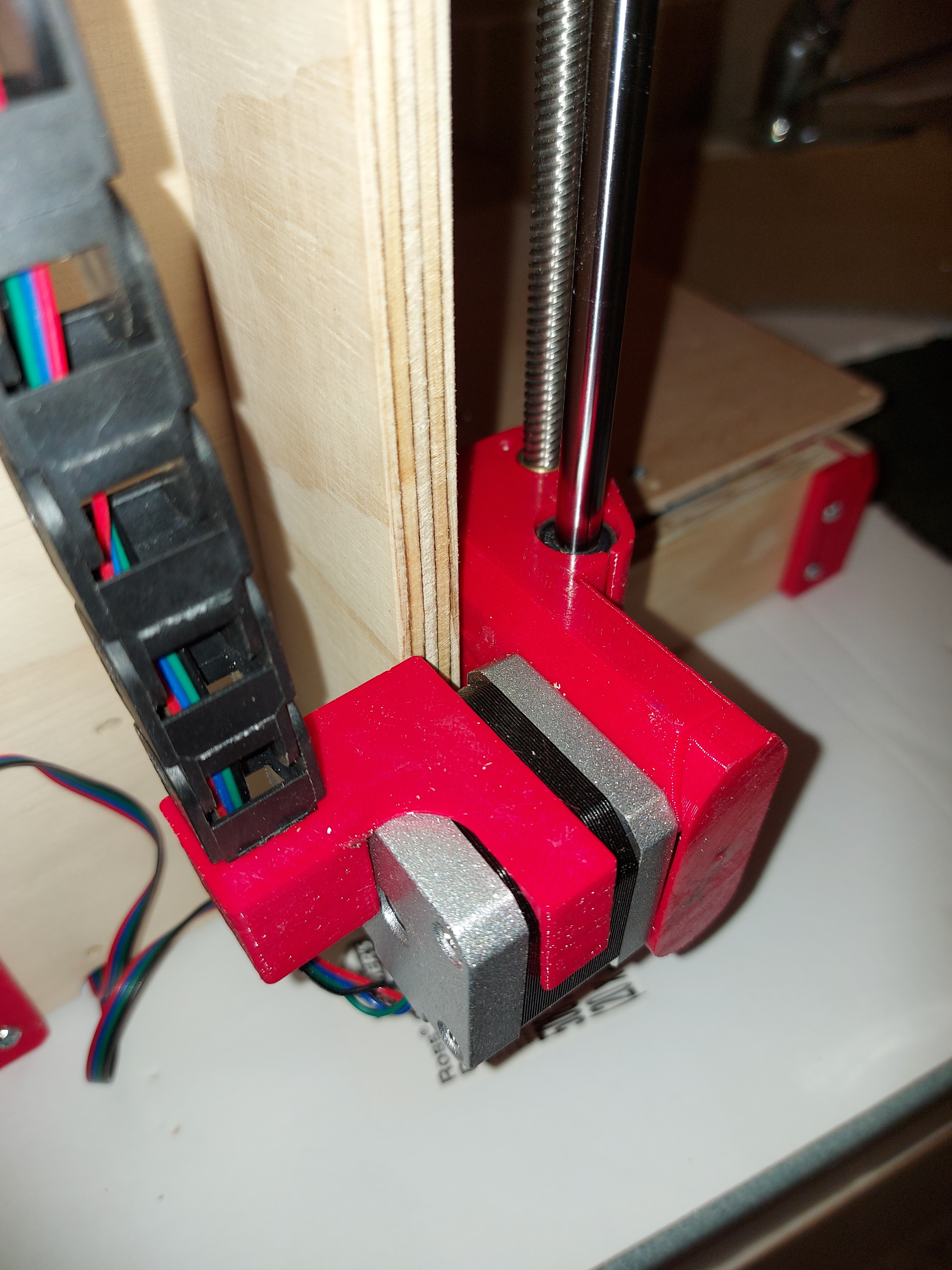
so I’ll have to use a different colour until I can get some more. I was hoping to have it all uniform, but looks like that’s not going to happen.

Well, I was going to re-do that IR probe mount anyway, so I’ll add in a mount for a part cooling fan.

I should have it running this weekend, barring surprises.

My crimper hates me. Good news is, the feeling is mutual.

Anyway, the wiring is a hot mess, but the printer is running. I had to reverse the extruder, and I haven’t done any calibration of X or Y. I expect that they’ll be fine, really. It’s a pretty well known formula. Z is going to be perfect, because it is.

The machine homes perfectly, I even got the IR sensor offset as close to right as it’s going to be without some real fine tuning. I heated it up enough to check that the extruder steps/mm is about as close as my tape measure will show me.

I did end up spending more money on this than I had initially planned. I bought new motors, to keep the ones I have for the LR2. I had to buy smooth rods, LM8UU bearings and leadscrews, which I thought I had, plus a few misc tools like a multimeter, because the one I have has gone psycho. I also bought a spool of filament that I should have known was coming, but somehow expected that I could get away with what I had. (Could have, too, if I hadn’t needed to re-print so many parts to do the 20T pulley modifications.)

I have about a half of a spool of lemon yellow PLA that I will test this printer with. I’ve never tried a Benchy before… But I’ll probably just print some cable clips or something simple to start.

1 Like

I really liked this idea because it’s so clean. I wanted to use it on my x axis on the lowrider but the heat shrink is not strong enough. It might be enough for your printer but it does not take much to pull those apart. I did try it a second time and added a bit of epoxy to the belt under the heat shrink and that was strong enough to break the tie strap I had looped through the belt end before the belt slipped in the heat shrink. Even after bending and twisting to try to break the epoxy. Just something to keep in mind.

Looks good, man. Kinda inspires me to get off my ass and get the one that I just built all tuned up and working properly. I spent all of this time building a machine, but then I got frustrated with cooling issues and shitty overhangs. It has collected dust in the corner ever since :confused:

1 Like

I haven’t got to tuning it yet.

Adding in the wires for hotend, heat bed, thermistors, etc hasn’t done anything good for how the wiring looks. I had intended to use a lot of braided sleeve, but it’s not in place, so “a hot mess” is how the wiring looks. I still don’t have a part cooling fan solution either, so overhangs aren’t going to be great, but then again, I haven’t got a part cooling fan for my main printer, either.

When I tested the idea, the belt section I tested stretched, and teeth broke off before the clamped section let go. Any torque that’s going to break teeth off of the belt will do so at the drive pulley, or so I figure, and if it’s going to stretch the belt, something else is wrong. No way the printer’s belts should ever be subjected to more force than this can handle.

Of course, I’m using 6mm belt. 10mm belt is a little different, because in order for this to work, the belt has to remain flat next to the clamped section. but comparing it to the printed clamp that was originally supposed to hold one end of the belt, and now holds the X carriage in place on the belt, and the same clamp holding the build plate to the Y axis, I don’t think that this is the weak point in the belt drive system.

1 Like

Possibly a final update on this.

I wish that I’d made one more minor modification. The heated bed that I have is 220mm by 275mm, allowing for about 205 by 255mm build area, and the Y frames as they are allow for more or less exactly 220mm of movement, so my build area is about 205mm by 220mm.

It’s really not a big deal, I don’t know that I’ve ever actually used that last 10mm of build area for anything except testing. I think I might have designed a fan grille for a 20030 fan that was 230mm in length once.

Anyway, I’ve decided to do a couple of things for final firmware tuning then give it to my kid, who wants to be an engineer.

  1. define the actual limits of the machine so that it won’t try (once homed) to crash the head into the bed, or move beyond the X or Y limits of the machine.

  2. Enable soft endstops so that it will reject Gcode that tries to do that.

I’m pretty sure that if I were going to keep this machine, I’d go back to a direct drive extruder. I can see the benefit to the Bowden setup, even as is, the machine is considerably faster than my leadscrew based printer. If I had built it using a Duet, it might even have supplanted my main one. The design is of course based on the venerated I3, but Ryan’s personal touches, plus the beautifully rigid plywood frame make this so far superior to my first I3 that it can hardly be called the same. I see the MKS board as the primary limitation of this machine in the end, and then really only because I have to sneakernet the files to the SD card in the LCD. Well, maybe I’ll let it live on the desk next to my Slicer PC and connect via USB to that machine until the kid’s birthday. If I like it that way… I might need to build another one, and I can extend the Y frame by 35mm… But I’m actually pretty sure that what I want to build will be a CoreXY printer, most likely based on MGN12 rails (Seeing as how I alreay dhave the rails.)

2 Likes

I have started to build a corexy based printer sooooooo many times now. I can never get through all the design choices. I got a good idea late last week, might actually start another one soon.

1 Like

I built the gridbot and it works great. It is very easy to work on. I recently installed klipper. It seems very capable.

1 Like

Okay, benefit or no, the Bowden tube is irritating, so I’m going to put in a direct drive Mk8. This will also allow the part cooling fan as supplied with the STLs for this printer. I’m using a differential IR sensor, but I changed the print bed surface to black printbite, which the IR sensor doesn’t like much, so a BLTouch clone will be here Saturday. I’ll need to figure out a mount for it, but that shouldn’t be too big a deal. Also will need to change the firmware, but that’s easy enough, too.

In preparing the Mk8 extruder, I ran into problems. I had to re-mount the hot end to change out the heater cartrige to a 24V one, and broke the throat. There’s a really fine line between not enough tension to hold the heat break steady and enough force to snap the stainless steel. It took me a couple tries to get it right. Changing to a 24V fan was easier, but my 24V fans are a little thicker than the 12V fan it came with, so I had to lose the fan grille, since I didn’t have 3mm screws long enough to make up the difference.

Why 24V? Because that’s what I’ve been using for 3D printers, so that’s what I have for parts and power supplies, etc. I actually do have a 12V 480W PSU, so I suppose that I could have used a 12V heated bed, and left the extruder and hotend as 12V. In hindsight, it would have been easier, but now that I have everything set up… I’m going to leave it this way.

I think keeping it all at one voltage level is ideal, even if it takes more work to do so. Changing everything over to 24v is better overall anyways. Everything has the potential to be quicker, and assuming the parts are the same wattage, you’ll move less current which means less power loss.
I’m awaiting new photos of your build when you get the chance. I’m really impressed with your work so far!

Nuthin’ is ever easy…

I’d been using the IR probe with the E3DV6 hotend, because I had it and because I had a mounting solution for it.

I also changed the heated bed to buildtak, and it doesn’t seem to like the IR probe much. It still works, but it’s not as consistent as I would like. So… BLTouch? Sure, why not. I had one that I bough yonks ago, and never took out of the box. Let’s see… How to mount it?

So what I’m seeing is this: The Mk8 extruder has the motor on one side, and the hotend cooling fan on the other. The part cooling fan is in front and the X carriage is in the back.

The closest that I could mount the BLTouch would be behind the X carriage. Looking at clearance for things like the belt zip tie, it’s not gonna be pretty to do that.

It’s not so bad if I am willing to accept both an X and a Y offset for the sensor. I’d really rather not, but that’s looking like how it’s going to be.

Well, off to search Thingiverse for a BLTouch mount…

The only downside to a larger or double offset is just the area of the plate you can probe. Other than that, is really doesn’t make a difference. Same accuracy (of the sampled area). I had the same initial reservations.

Did you see my MK8 bltouch mount on thingiverse? I snapped it right on the heat sink.

Yeah, found that, it’s printing now.

Just for interest’s sake, I Tinkercad edited the X carriage to put the mount on the bearing side, trying to keep it clear of the belts, but making it adjustable started getting too involved.

1 Like

So it’s printing.

I have some massive quality issues due to the fact that I put a really old spool of PLA on the machine, which hasn’t been stored in any kind of drybox for a couple of years. Also, apparently my Print Bite sheet holds on to the PLA better than it holds onto the print bed, so my first print attempt, I ended up pulling up the sheet before the print came off. I’ll give it another shot. I’ve got 2 more sheets, but if that trouble keeps up, I’m going back to glass.

The printer is fast. I gave some thought to settings, asking for a max of 120mm/s print speeds seems possible for infill, and up to about 90mm/s for inner perimeters. I may push it to see how fast it can go, but this is a decent starting point. Faster than my main printer, after all. Dimensional accuracy is good (At least as good as I can check, given the rough surface.)

Probably some fine-tuning still to do, I’ll swap in a new roll of filament and try a few more test prints

1 Like

Ugh. More massive print quality issues. The extruder kept missing steps, so although the steps/mm were right, I got one fugly little maneki-neko.

Then I remembered that I basically didn’t touch the stepper drivers from when I had that control board connected to my Primo. Check with a volt meter.

  • X: 745mV
  • Y: 736mV
  • Z: 772mV
  • E0: 946mV (?! Holy crap! How did THAT happen?)
  • E1: 735mV

So… Counter-clockwise turns up the current, and at about 1/16 of a turn, the E0 stepper driver let out some magic smoke. I have a couple spares, fortunately. Well, now I have ONE spare.

These are super picky. Touch the pot with a screwdriver, and the mV goes to single digits in less than you’d think possible. Trying to target between 300 and 400mV. Breathe on the screwdriver wrong and you skip back and forth between about 150mV and 600mV. I finally got them all into the 300-400 range, except Y, which is ~500 and I cannot get it less than that and more than 50. I considered using the spare, but these are 1800mA rated motors, (And I was apparently over that for the extruder! No wonder it wasn’t behaving.)

Reprint the same job from SD card, and it looks pretty reasonable.

I need to adjust my slicer settings. It want to turn the part cooling fan on all the time, and I don’t want it to. I only want the fan for bridges and overhangs. Well, it’s not that great a fan anyway, so maybe it doesn’t really matter. I’d like to put in something with a little more oomph.

Some of this is testing ideas for the printer that I really want, so some options to play with, and if I get something usable from this, so much the better.

Crap, I forgot to take a snapshot of the money-cat.

1 Like

I used to have a tiny plastic screwdriver, might have been ceramic. That really helped with the pots. Some though, were really a pain. DIGI pots for life!