Hi,
I want to build a custom spindle assembly for my CNC.
I have a ER16 straight shank and there are a lot of designs available. Spindle should be turned through a toothed belt and a reduction set of pulleys by a BLDC motor.
Intended one is coming from a 12V Lidl- Parkside cordless planer. It is a powerfull motor with a good torque (imagine that the planer’s drum is something like 50mm diameter) and 11000 rpm. What it is not specified is motor’s power. I guess I could also overvolt it without issue but as I want to use it continuously, it is better not to do it.
My main question (as planer hasn’t an adjustable speed controller) how can I controll motor’s speed safely.
I found on net that generic BLDC motor’s speed is adjustable through its supplied voltage and I have a 30-40A PWM controller (continuous 20A meaning 240W continuous at 12V).
Can I supply a BLDC motor through PWM controller? Won’t PWM interfere with BLDC’s built-in controller? I must mention that the motor has a built-in controller - sensorless apparently. It has some unused inputs on board (one of them could be for RPM controll) but I couldn’t find any info about it and honestly I reject any trial and error approach.
All I want to know is how can I safely power the motor adjusting also its speed. Hopefully a PWM voltage is not affecting controller which is an electronic device … or maybe I can smooth voltage and how -to make it work?
Thank you in advance.
I am curious about how this might be built, but I’m by no means an expert on this. The BLDC motors I (sorta) know about are RC style motors with 3 fat wires, and I would drive that kind of motor with either an RC ESC with a RC servo-style PWM signal or with something like ODrive. ODrive requires an encoder so there is more to set up for that.
It sounds unusual to me for a motor to have a built-in controller but like I said I don’t really know.
I am curious about the mechanical setup, and how a spindle would be constructed to have better quality (stiffness, runout, …) than a router spindle. I know such things as cartridge spindles exist but the entry price for those is pretty outrageous.
Hi Jamie,
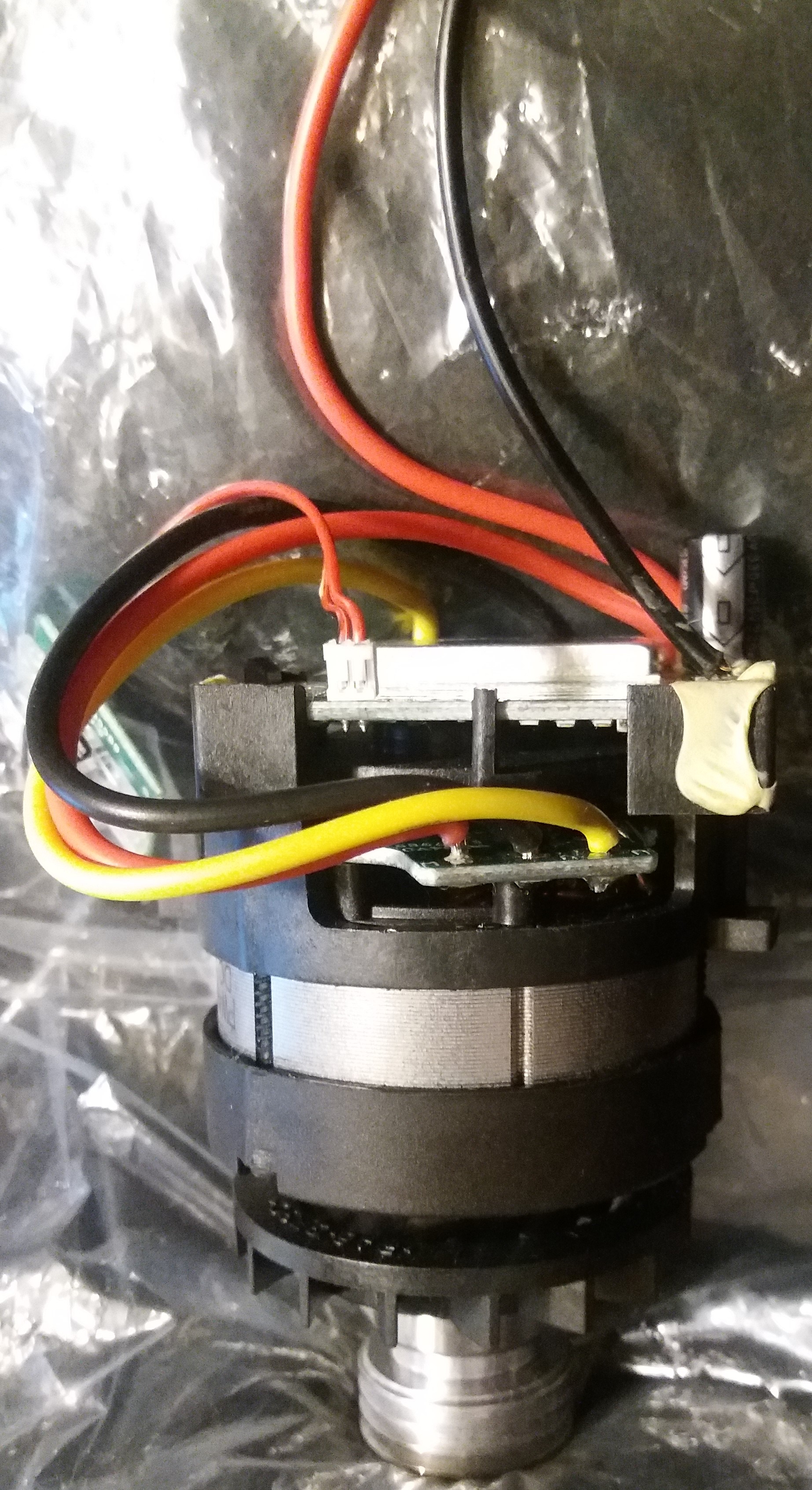
I have attached pictures of the motor.
It’s a compact, integrated system (as it should be for a powertool).
On the left a LED battery status indicator can be seen (not important for my application) and on the right the 12V power line to the battery with the push-on switch.
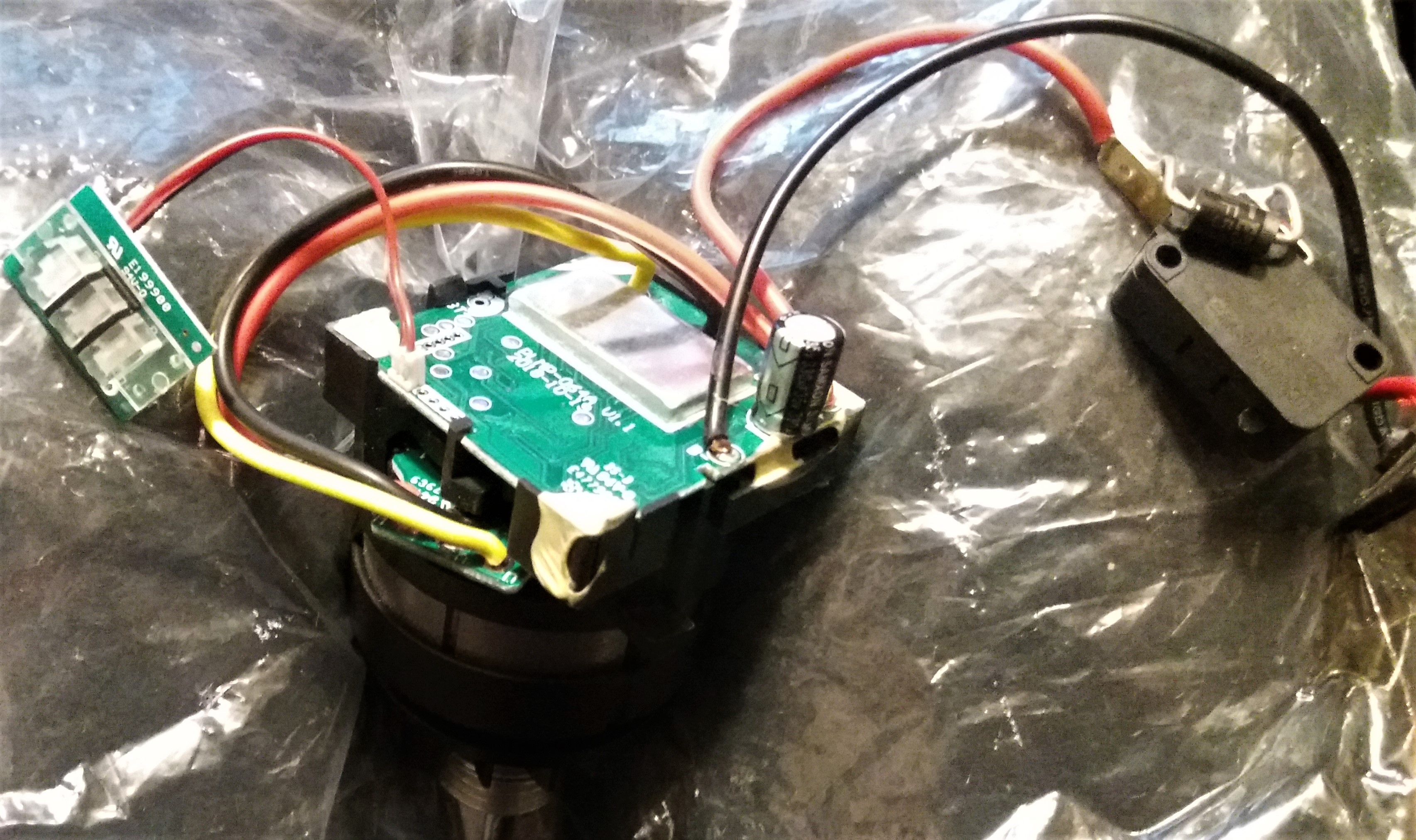
The motor has 3 bearings, of which one is close to pulley.
On the controller you can see 2 sets of connection holes unused (left side) but I-m not curious what they link to (because I don’t have necessary skills).
The motor runned very smooth in the original tool but only at its full power.
About spindles (I know you met them but maybe I was not clear enough in my description), here are 2 general links:
http://www.metallmodellbau.de/Eigenbau-Universalspindel.php - you can use translator.
https://reprap.org/forum/read.php?131,315687
Of course it is not the smallest setup…but has advantages:
Spindle can be built rock solid (some use 2 bearings at each side of the shank), with high load capacities depending of the bearing type you use. (not the case with 200-600W chinese motor spindles which are not really made for high loads - not to mention catastrophic operation)
Usually reduced runout is easy to achieve (if you have decent quality components).
You can have 2-3 or more pulley sets with different transmission ratios. You can swap them according intended application. Aluminium milling becomes achievable with lower RPM and higher torque. You can keep motor on high RPM with good characteristics and cooling while spindle goes low RPM.
Motor is an independent unit - you can upgrade it anytime. Belt transmision is very forgiving with the motor; loads are low and shocks are absorbed by the belt.
Looking at the components, I highly doubt it. The board attached to the motor is the speed control. It’s job is to run the motor at a specific rpm, no matter what the battery voltage is, and no matter what loads are acting on the motor. In a brushless motor, the current gets sent through the motor at controlled times that add up to 11,000 rpms. If you want to adjust the rpms of the motor, you will need to convince the speed controller to do that, and unless one of those unpopulated solder points is for a trigger or something, you’d need to change the code on it.
The controller looks like it’s configured to run only at “full speed” since I am not seeing any other wires to give input to control the speed.
A motor will produce back-voltage that increases with speed, and the voltage of the supply will determine the maximum speed. When the back-voltage matches the supply voltage, no more torque can be produced. This relationship between voltage and speed is described by the “kV” rating of the motor.
However, controlling voltage is not generally used to control the speed of a brushless motor. They are usually controlled via the timing and the current through the wires, much like a stepper motor. Your controller board probably has a sensor that detects the motor position so that it can synchronize the current with the position of the motor.
I think your choices are to use the entire assembly as-is, and you get fixed speed of the motor, or you could separate the controller from the motor and use another method to drive the motor. Using an external controller is probably possible if the three fat wires connect to the motor windings directly and the small circuit board is ‘dumb’.
If you find this sort of thing to be enjoyable then it could be fun to hack the motor to be driven by an RC ESC, but it could be difficult to get working. If it were me, I might do the following:
- Buy a high current ESC that can accommodate a BLDC motor
- Try connecting the ESC to the 3 big wires from the tool motor (not using sensor), and see if you can get decent performance and speed control.
- If you don’t get good performance and you run out of patience, buy a BLDC motor that fits the ESC and go forward with that.
Don’t quote me on this, but I think the sensor is mostly useful when the motor is turning at very low speed. At higher speed a controller brain can examine the voltages produced by the coils and infer the proper phase. So I think you can run in sensorless configuration.
Hi,
Thank you both for your applied answers! They are very much appreciated.
Of course they don’t make me happy, but help me define further steps 
On first I will go full speed with several reduction pulleys:1:1; 1:2; 1:3; 1:4; small pulley with 15 teeth. So already few speed choices. It was intended anyway. 1:4 means below 3000 RPM, quite low - for the beginning.
If motor proves to fit to purpose, I will try to go to high current ESC . I don’t want very low speeds - only not to burn my tools.
Convincing existing controller is very tempting but I’m very sure I’m not able to do it the rational way. Maybe if step 2 works (new ESC), I will play with it…Perhaps it accepts standard controlls - it should be reasonable; analog (or PWM) input signal, nothing to lose…
Hi, please help with advice.
I have bought a cheap 30A (max 40A limited time) ESC which is largely used in quadcopters control. As I look at it it seems to be well protected against water and shocks in detriment of cooling.
As I intend to use it in a small mill/router, stripping it from yellow protective hose and providing additional radiator and fan cooling would increase capable amperage and how much (say up to 32-34-36…)?
Is it worth this approach? I would say keeping it cooler would worth even for same factory spec. but is it true?
I haven’t find such direction both in various forum threads or Youtube tutorials.
Doesn’t the same wrap that protects against water and shocks also protect the high amperage connections from shorts? If considering machining aluminum or other conductive materials, I would leave that protection in place.
If you need more amps, why not get a bigger ESC?
Hi Tom, thank you for your answer.
I don’t know yet if I need a bigger ESC. The main reason is just that for me plastic is a thermal insulator so a no-no when comes to power electronic circuits. For a quadcopter mechanical protection is important and low weight is important, but these are not the highest requirements for such kind of circuits in general application. Plastic protection is rather a limiting factor (well, it is the air flow that compensates for quads).
I want either to suck as much as I can from it or to protect it more, considering potential hours of continuous operation/ not to mention instant load peaks which are different from model planes/cars.
For metal chips I am considering an external housing, almost certainly aluminum and with thermal bridge to power transistors. And my curiosity was how much good cooling can increase Amperage. For many power circuits there are 2 specs - one for standard delivery (no cooling) and one for radiator mounted and the difference is sensible (obvious if you consider in one case maximum junction temperature radiated by nail surface and in the other case by a rose-in-the-wind).
Regards,
Mihai
It may be dipped in something inside the cover too. Which may make it more difficult to cool and also still somewhat resistant to chips.