So I would like to make some wood bowls. My goal is a 6"×6"x3.5" bowl. I know that is a deeper DOC than can be done normally but the concave shape should make it possible. I also realize if I want it round on the outside I would need to do two sided milling. But being new to CAM I’m not sure how to approach concave shape. Can this be done is Estlcam? Is there better free software to use for this kind of project? I know VCarve pro can do it and is worth the money but am not yet ready to invest in that software. Any help or advice is greatly appreciated.
Fusion 360 (the personal/free version) can author and do the CAM for this kind of milling, though the learning curve is steep. Beyond the authoring, there are some “mechanical” problems for two-sided milling you need to solve.
The typical way to do two-sided milling is to use pegs on either the vertical and horizontal centerline of your authored stock, and use the center top of the stock as the origin point for the job. Two bore holes that pass through the stock into the spoil board are authored. Using pegs on these holes allows you to align your front and back cutting jobs. But, unless you have a very large Z working space on your machine, you don’t have the space for this technique. For a 3.5" bowl, you would need a minimum of 8" of Z working space, and probably more.
There is an alternate solution for two-sided milling that reduces the required Z working distance somewhat. Someone posted this idea on the forum, but I have not yet tried it (yeah forum). It requires you have two fences (horizontal and vertical) that establish a corner. And the XYZ edges of the stock must be perpendicular. Use the corner the fences and the top of the stock as the origin point. When you flip the stock, you also rotate it 90 degrees so that the same corner used on the first side is in the corner of the fences. The same origin point is used for both sides, so if you leave the steppers engaged, you have an accurate origin point after the flip, and the fences keep the stock aligned. This does require you to author the second side job at 90 degrees from the first side.
Even with this alternate two-sided milling technique, you still need a lot of Z working space…I figure 6.5” minimum if you use double sided tape rather than clamps. You can cut this number down some if you have a drop table.
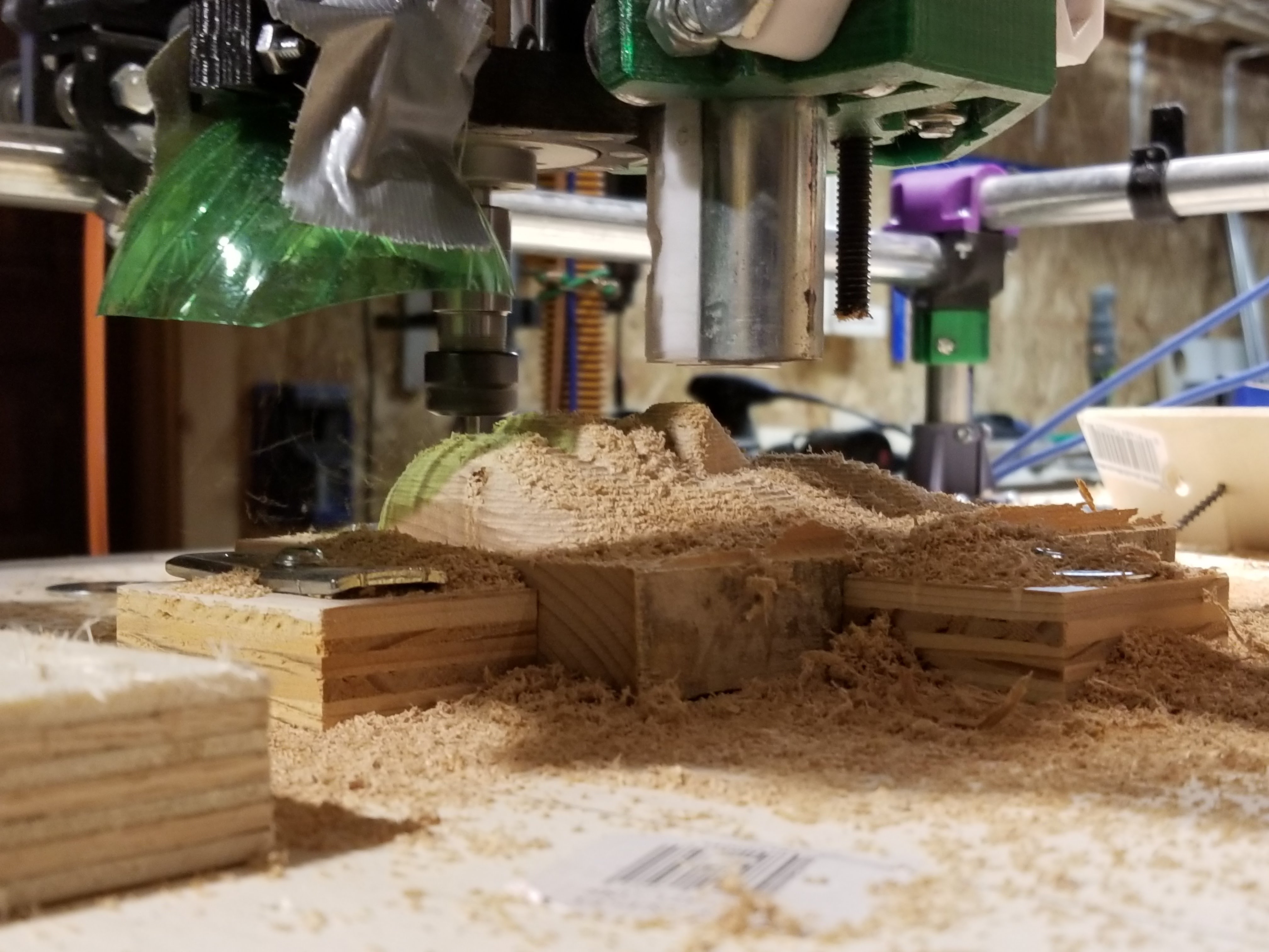
I have a hole cut out in my table(originaly for end milling) that I can pull out and rig a drop table into so Z height shouldn’t be a problem. My thought for doing the two sided milling for these bowls was as follows;
Mill the bottom of the bowl first, in the center of the bottom of the bowl drill a shallow hole.
Put a whole in my spoilboard that is more than 6" from each axis.
Place a dowl in the hole, flip the bowl right side up and place the hole in the bowl onto the dowl. Securing the bowl to the spoil board with tape so it won’t spin.
Then set my origin to the center of the bowl and Mill the top of the bowl.
Since the bowl is round I should only need to constrain the center and everything should line up.
What I don’t know is how to do the cam for the rounded edges. I will have to play with f360. And see if I can figure it out.
To make rounded edges like on a bowl with f360, I like to use 3D contour, very high feed rates and small step downs (technically step ups). I change linking to no lead ins or lead outs. I also set ramp type to plunge and transition type to smooth under the ramp section. Bottom up order is set in the passes tab; this is important to avoid getting a bunch of fuzz with an upcut bit. You could probably order top down with a down cut bit, but I have not tested that.
Alternatively… I have been wanting to try this myself… you can use a round over bit and program it into f360 as a profile cutter. It would limit the radius but would result in a really clean rounded edge.
Thanks Kev some good info there. My plan is to do a rough pass with a single flute upcut and the finishing pass with a ball nose to try and get a nice finish. I haven’t tried using a round over bit. Might be worth a shot!
I am considering some 2 sided milling lately and without dual endstops I don’t trust my ability to align the tool with whatever fixturing. So I was thinking I would mill the spoilboard holes and the top of my workpiece (including alignment holes) as one operation, then flip and use dowels and run the second operation without de-energizing the steppers.
Using the diagonal-flip trick to minimise sensitivity to skew, I think it should be possible to get quite good alignment between the two sides without an absolute reference or perfectly square machine.
As for your bowl, if it were me I would make it some shape other than circular, because non-circular bowls can’t be made on lathes, which makes them more interesting.
I’ve done a couple of pieces where I needed some precise placement in already cut pieces. Locating pins are good for 2 sided cuts in fresh material, as far as it goes.
For a bowl, what I’d probably do is the following:
Do the inside first, so that you have the shape of the rim of the bowl to work from, that will not need any changes.
Put a piece of scrap, or foam or something down on the spoilboard, and cut out the shape of the bowl rim. You can then place the bowl upside down in the cutout area. It should he a reasonably tight fit, and will have the bowl located on the spoilboard at the same coordinates as the cutout that you just finished. This will work for non-round shapes best, but should be OK for round ones, too, though they’ll need something to keep them from rotating.
When you do the inside of the bowl you’ll need to cut out the rim shape, and either cut all the way through, or clear away the excess material from outside enough to locate the piece in the hole in your scrap material.
As a bonus, if you pocket cut your scrap, you’ll also have a known level zero plane that the workpiece sits on.
Interesting idea. So for a basic rectangle shape, you would do one side in “portrait” and the opposite side in “landscape” with the idea that any machine skew would then be towards the same corners?
Your right and that is the end goal, but since this is my first time doing a 2.5D cut and 2 sided milling I figured I would start with somthing simpler before making somthing more interesting.
The registration pins have to be part of the pattern for this to retain high precision, because the axis of the flipping is dependent on the skew. If you had fixed pin locations then you would lose some (maybe all) of the benefit.
Very cool. Should also work/adjust for the cut into scrap that I used, since the scrap cut would share the same skew (Or hopefully lack of it) that you’d have in the first side.
Vectric tutorials are free and I found this one on making an interesting bowl shape very helpful in designing the oval plates I showed in my recent post> https://youtu.be/UeSqPau3AIQ
(2-sided job)
The most important thing is a good long round bit. How deep your bowl is will mostly be determined by that, unless you do some tricky 90 degree mounting mentioned above.
I have done this for 2 sided pcb milling and it worked not so well for me. In that case at first I just milled a pocket in some scrap mdf such that there were 2 perpendicular rails sticking up. The alignment of the fixture is not critical, however the pcb material I got was way out of square… not even parallel on the sides either. So I fell back to using 1 straight edge, flipping 180, and using the bit to register in a hole after the flip (always a hole in a 2 sided pcb). This is a variation that is slower and prone to error though. I think the 2 pin 90degree flip is better for production. You can do the registration holes on a stack of stock quickly. In fact I think it would work if you do the holes independent of the fixture. As long as you use the exact same holes on future cuts, the stock holes can be done any later time and still work. This could work well… just stock some like 1/4 dowels and put holes in strategic places on the table that work with a variety of projects. Then just add whatever pair of holes works to the stock. This way you could fixture and cut several unique 2 sided parts in one operation.
Not sure on estlcam, but handling the 90* orientation is pretty simple in f360.