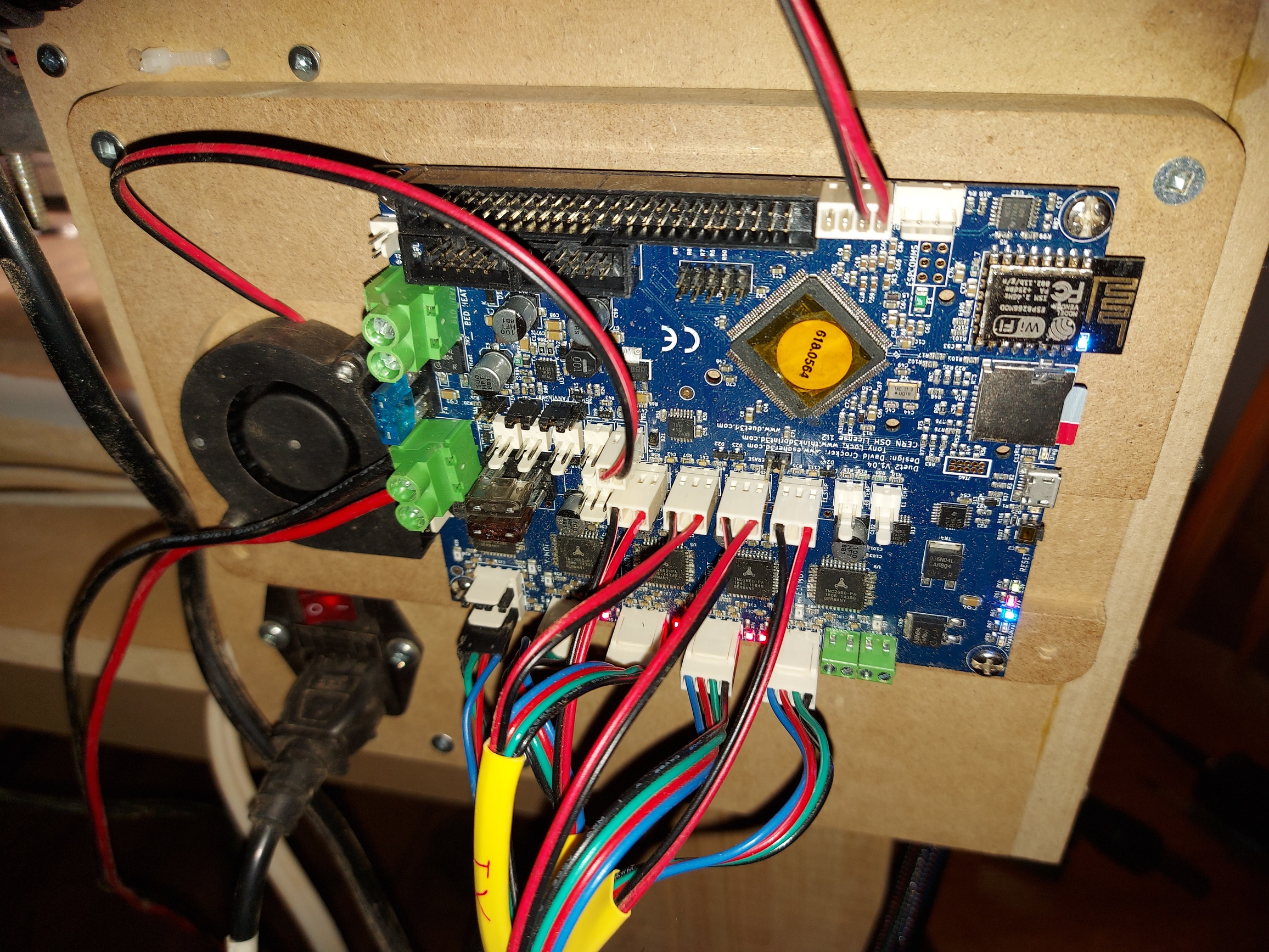
Did you plug in your driver all the way?
Check this image 20200929_233909
Yeah, I saw that the drivers had been pushed a bit when I did the electrical. Snapped those before I turned it on. I did fix that before turning it on, the E1 and X drivers both had been pushed out, and I had to replace the adhesive on the X driver heatsink. Should have left more room. I also plugged the 5v power wires to the Pi all the way in, too. Just in case anyone was wondering. 

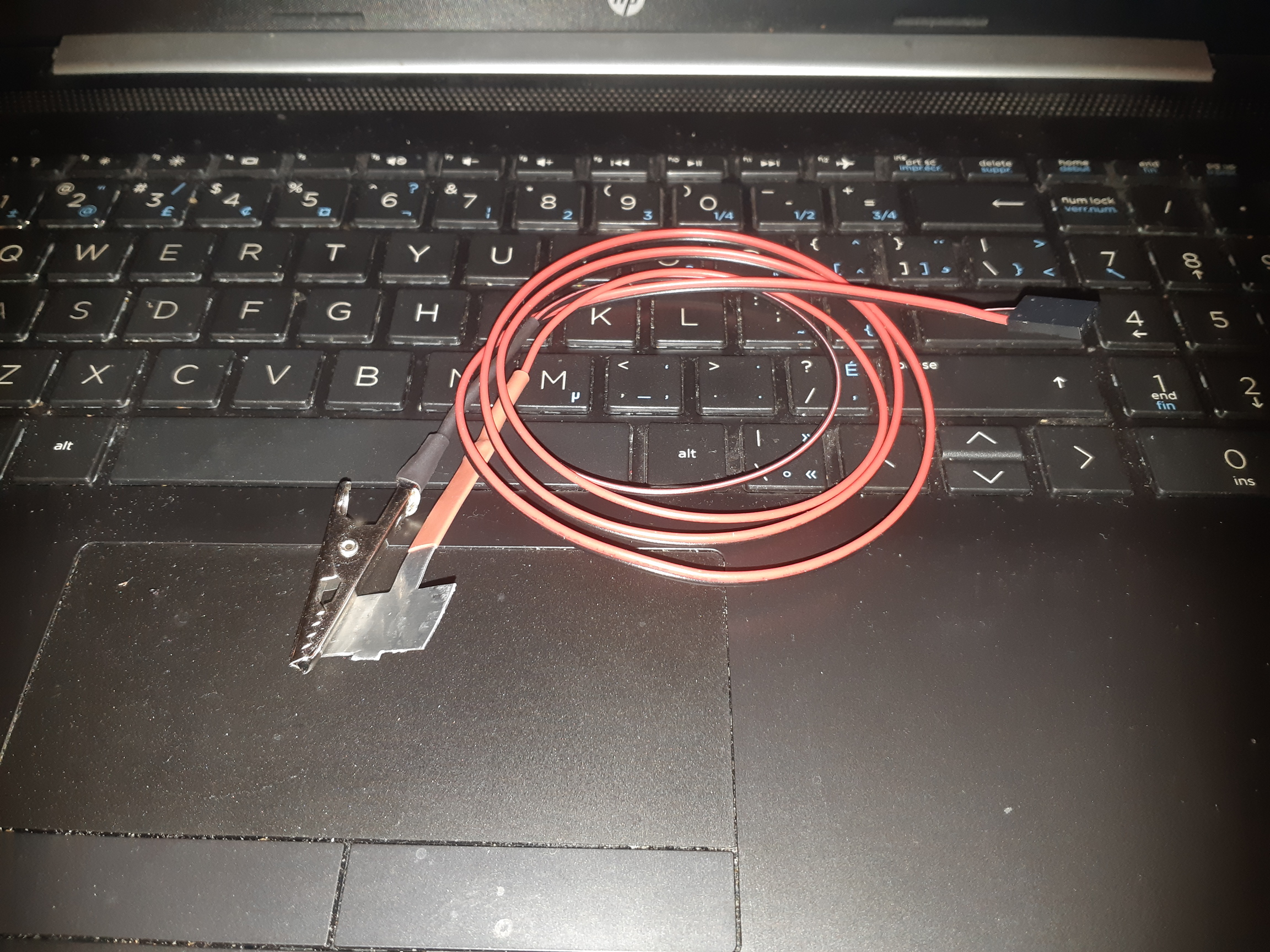
Today’s MPCNC project wasnt spectacular, but maybe important. A DIY touchplate. Some 2 pin cable with a 3 pin Dupont connector, to plug into the endstop connector.
A small alligator clip on the ground wire and part of an aluminum cable tie on the signal pin. The flat part had 3M foam tape on one side, which I removed. I don’t know it’s exactly 0.5mm, but it’s really close. I think it will substitute for the V1 version.
Edit: Okay… Good thing I put that heat shrink on there… Turns out that if I’m touching the aluminum at all, it reads as triggered, even if I’m not touching anything else. The aluminum is softer than stainless so I have to be careful how I press it to the work to home Z. Other than that, and not having a place to hang it when not in use… Works great.
Using the Home Z function sets the contact point as 0, and not 0.5, but that’s workable. Most times, I’m not going to miss a half mm anyway, though I might for some projects, so I’ll have to fix it.
Well, the aluminum touch plate seemed like a good idea at the time. The problem is that it doesn’t flex, it just bends. So if you can hold it down flat enough, it works great. Usually though there’s some uncertainty as to the height above the work that it homes to.
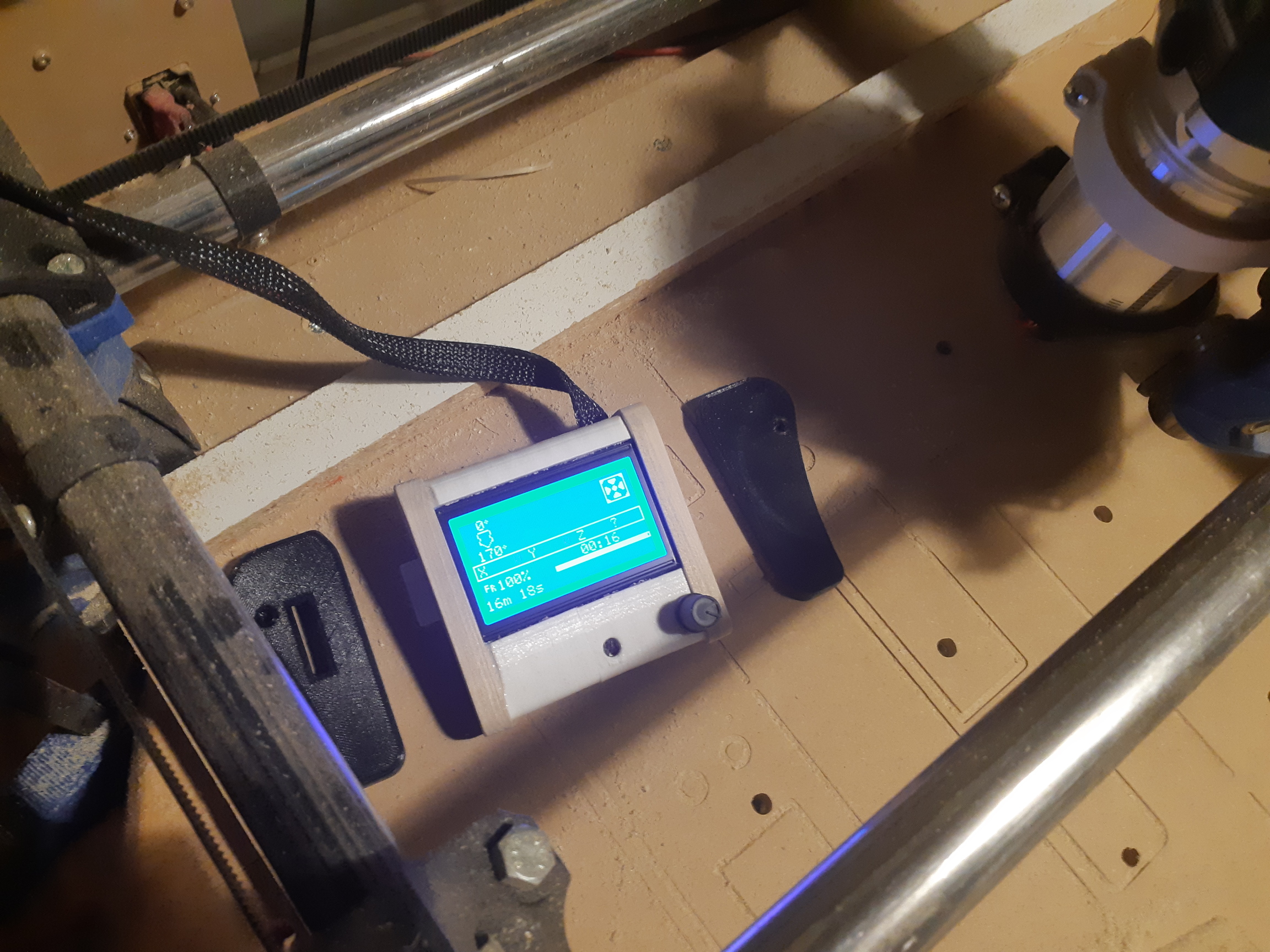
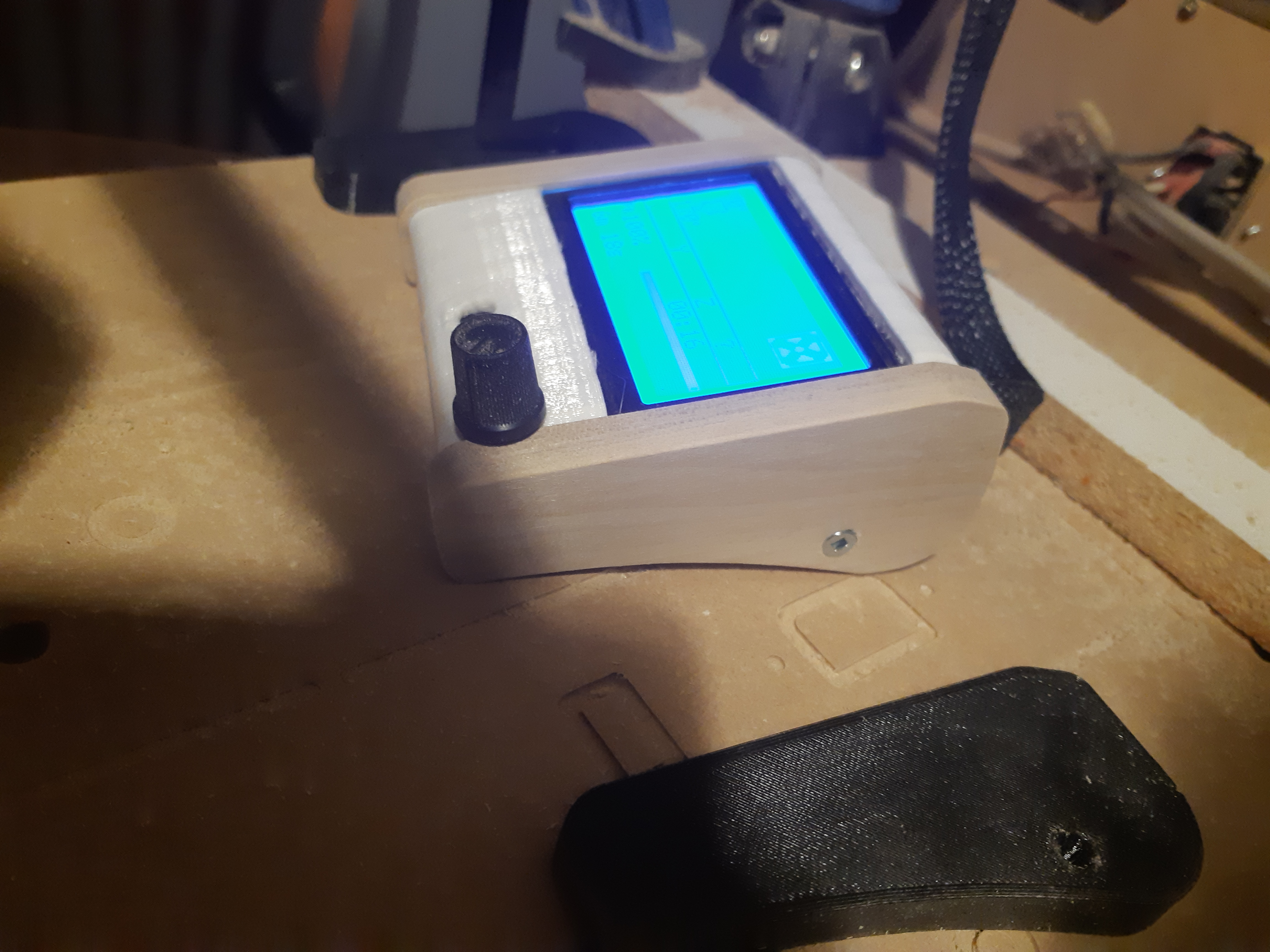
Working on the 2.5D LCD case next. Bought some poplar for first run, but hoping to manage some red oak.
Sounds like you need a 20K to 40K pullup resistor between S and +. Common boards use an internal pullup resistor, but if it is not functioning…
Using the Home Z function sets the contact point as 0, and not 0.5, but that’s workable. Most times, I’m not going to miss a half mm anyway, though I might for some projects, so I’ll have to fix it.
If you are using Ryan’s firmware from his GitHub page, then there should be a custom menu. You can modify that menu to take the the 0.5 into account. Search for CUSTOM_USER_MENUS in Configuration_Adv.h.
As an alternate, I saw one person on the forum put a bit of code in a .gcode file and executes it to home Z
G28 Z
G92 Z0.5
G0 Z5 F480
1 Like
I think it is functioning, the other switched all seem okay. I need to upgrade my firmware, I got ahold of an old version linked somewhere in the documentation. I have the latest version but haven’t flashed it yet. I think the home in the custom menu now sets 0.5mm when you home Z.
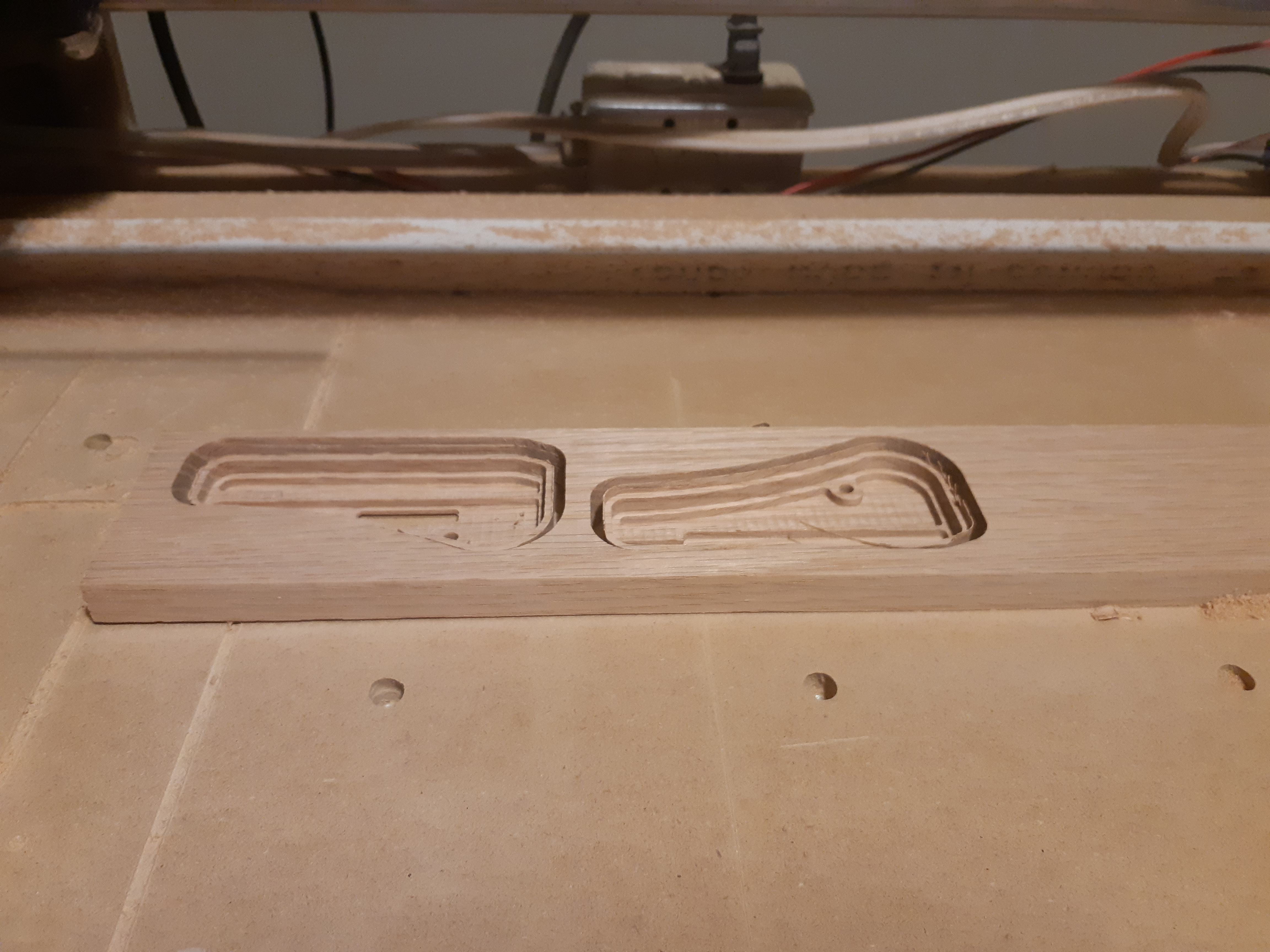
I’d forgotten how much I like the smell of oak sawdust. I’ve been making stuff from MDF for so long… I am using the poplar for the MPCNC, the oak are going to be for the ZenXY table.
3 Likes
I just look out on GitHub at the latest version of the firmware for Rambo Dual, and it does not take the 0.5 into account. Line 3175 currently is:
#define USER_GCODE_2 “G28 Z”
…and could be changed to this…
#define USER_GCODE_2 “G28 Z\nG92 Z0.5\nG0 Z5 F480”
…to take into account the 0.5mm of the touch plate.
Note that the G0 Z5 F480 is optional and just lifts the router to 5mm
Having the Z probe triggered by touch indicates to me a problem but perhaps one you can live with.
Well, with use, I’ve fixed some things, discovered others.
-
The pullup resistor for my Z Min endstop seems to be NFG. It’s enabled in firmware, but doesn’t seem to work, my multimeter records the input pin as floating. I wired a 47k resistor between the +5V and the trigger. Problem solved.
-
My tool isn’t perfectly plumb. I noticed when pocketing with the surfacing bit. It leaves a ridge that I can see, and just barely feel with a fingernail when using linear pocketing in the X dimension. I got around it by changing the linear pocketing to 90 degrees, but I would like to fix the problem. This is going to be a pain, since the amount is so tiny, I can only really tell with the 1" surfacing bit. I’ve been putting it off…
-
My 1/8" bits seem to be a little smaller than 1/8" I’m going to have to cut some grooves and measure. The hinge pockets in my cribbage board came out a bit undersized. I suspect that I should be using 3.1mm instead of 3.13mm, but it might be as much as 3.08mm. I tried to cut the hinge pockets as tight as possible for the hinges to ensure perfect alignment, and they ended up being a little too tight, and I needed to fix them with a chisel.
1 Like
5 months later, and I still haven’t got the bit size perfectly fixed. Sometimes if I make tab and groove parts they need a little sanding to fit.
My MKS Gen L board seems to be having more and more trouble with arcs. I’m probably using them more and more in my CAD, now that I can, and it’s becoming troublesome. I can see that in Estlcam I can turn them off, and it will use straight segments instead, but I’d like to not have to do that.
I spent some time looking at the SKR Pro 1.2, but there doesn’t seem to be an inexpensive choice for that. No matter how I do it, I’m looking at a substantial expense. Well, it’s less if I can still just use the same 12864 LCD, and not get the TFT35, though it’s all bundled in the V1 shop. (Which seems to be a better price than Amazon for the whole kit.) Of course I still have a “spare” Duet Wifi. Since that’s not really doing anything, I think I might just run with it. It will mean giving up the LCD, but the web interface is more than good enough, and I have a spare tablet that is up to the task of running it in a browser.
I need to re-wire everything anyway. One of my connectors broke in the drag chain and now the Y1 endstop doesn’t work. I’m a little worried that one of the motor connectors might also go, so I want to re-do things to keep all the connectors out of the drag chains.
Anyway, it looks like I’ll be putting the Duet into service, unless there’s a really good reason to get the SKR Pro. I suppose that I can put the Duet in and replace it later, it’s not like I’m buying it specific for this task.
So, I think I’ve got the config.g set up for the Duet Wifi. This is running version 3.2 of the RepRap Firmware (Latest as of time of install) and I’ve loaded the CNC version of the web control software. I’m considering the gamepad plugin for jogging the controller, but haven’t done that yet.
; Configuration file for Duet WiFi (firmware version 3)
; executed by the firmware on start-up
;
; generated by RepRapFirmware Configuration Tool v3.2.3 on Tue Apr 20 2021 01:19:12 GMT-0600 (Mountain Daylight Time)
; Monkeyed with by SupraGuy because obviously I know better than the configuration tool, lol!

; General preferences
G90                                             ; send absolute coordinates...
M83                                             ; ...but relative extruder moves
M550 P"MPCNC Primo"                             ; set printer name

; Network
M552 S1                                         ; enable network
M586 P0 S1                                      ; enable HTTP
M586 P1 S0                                      ; disable FTP
M586 P2 S0                                      ; disable Telnet

; Drives
M569 P0 S1                                      ; physical drive 0 goes forwards
M569 P1 S1                                      ; physical drive 1 goes forwards
M569 P2 S1                                      ; physical drive 2 goes forwards
M569 P3 S1                                      ; physical drive 3 goes forwards
M569 P4 S1                                      ; physical drive 4 goes forwards
M584 X0:3 Y1:4 Z2                               ; set drive mapping
M350 X16 Y16 Z16 I1                             ; configure microstepping with interpolation
M92 X100.00 Y100.00 Z400.00                     ; set steps per mm
M566 X900.00 Y900.00 Z60.00                     ; set maximum instantaneous speed changes (mm/min)
M203 X3000.0 Y3000.0 Z180.00                    ; set maximum speeds (mm/min)
M201 X250.00 Y250.00 Z20.00                     ; set accelerations (mm/s^2)
M906 X1200 Y1200 Z1200 I25                      ; set motor currents (mA) and motor idle factor in per cent
M84 S30                                         ; Set idle timeout

; Axis Limits
M208 X0 Y0 Z0 S1                                ; set axis minima
M208 X762 Y940 Z90 S0                           ; set axis maxima

; Endstops
M574 X1 S1 P"^xstop+^e0stop"                    ; configure active-high endstop for low end on X via pin ^xstop+^e0stop
M574 Y1 S1 P"^ystop+^e1stop"                    ; configure active-high endstop for low end on Y via pin ^ystop+^e1stop

; Z-Probe
M558 P5 C"!^zprobe.in" H5 F120 T6000            ; set Z probe type to switch and the dive height + speeds
G31 P500 X0 Y0 Z0.5                             ; set Z probe trigger value, offset and trigger height
M557 X15:715 Y15:915 S100                       ; define mesh grid

; Heaters
M140 H-1                                        ; disable heated bed (overrides default heater mapping)
M308 S2 Y"drivers" A"DRIVERS"                   ; configure sensor 2 as temperature warning and overheat flags on the TMC2660 on Duet
M308 S3 Y"mcu-temp" A"MCU"                      ; configure sensor 3 as thermistor on pin e1temp for left stepper

; Fans
M950 F0 C"fan0" Q500                            ; create fan 0 on pin fan0 and set its frequency
M106 P0 S0 H-1                                  ; set fan 0 value. Thermostatic control is turned off
M950 F1 C"fan1" Q500                            ; create fan 1 on pin fan1 and set its frequency
M106 P1 S1 H T45                                ; set fan 1 value. Thermostatic control is turned on
M950 F2 C"fan2" Q500                            ; create fan 2 on pin fan2 and set its frequency
M106 P2 H2:3 L0.15 X1 B0.3 T25:60               ; set fan 2 value. Thermostatic control is turned on

; Tools
M453 C"exp.heater3" Q100                        ; Set CNC Mode spindle on heater 3, frequency 100Hz

; Custom settings are not defined
This should be set up for dual endstops wired as NC switches. The touchplate should be wired to the Z probe input. I have ordered 3.3V zener diodes to put between the signal lines and ground to protect the input pins. I’m mostly concerned about the touch plate as that’s something that I’ll be touching with my fingers. I thought it might be a good idea to add a ground strap to the rails and gantry after seeing bits of foam sticking to them. This probably will also help with protecting the touch plate, if I can ground myself before picking up the touchplate.
Well, maybe I’m overthinking this part.
Well, I was hoping that I could plug the Duet in as a sort of test run, but the difference in the way the stop switches are wired makes that a little tricky. The MKS GEN L is wired the same way that most RAMPS boards are, Sig, Gnd, +5V with the NC switch between Sig and Gnd. The Duet is wired Sig, +3V3, Gnd. I still want to wire it with an NC switch between Sig and Gnd, which requires different connectors.
I have the connectors that came with the Duet, which I intend to use for this, as they will generate a better positive lock to the board. Loose connections are no fun at all.
I’m considering a base up rewire. A lot of work, but probably not too bad, really. Most of the work will be fishing things through the drag chains. One of my stop connectors has a bit of an intermittent connection problem though. I’d actually like to be rid of all of the connectors that I can be. I kind of wish I’d bought the kind of motors that have the connector on the motor itself, rather than wires. I guess it’s the same number of connectors either way, but that way none of them would have to be situated in the drag chains. I may solder and heat shrink, and keep those connections out of the drag chains too. Or maybe just re-do the stop connectors and plug it in. That one that is flakey bugs me though.
Oh how I hate crimping those little connectors!
My crimper leaves the end just too big to fit in the housings, so I need to squeeze them just a bit smaller with pliers. End result, it takes too long to do, and some connections might need another run.
Everything worked, but I connected the X motors backwards. I reversed them in firmware, but something ain’t right, and it’s late. This is the time in the project where I either choose to half-ass it or wait until tomorrow.
Tomorrow it is.
1 Like
Glad I didn’t force through it last night. I made a typo editing the config, and it resulted in turning off the web server, among some other problems that probably would have become worse.
So now it’s all connected up, the stop switches work perfectly.
I apparently don’t understand the workplace coordinate setup. My former tool change routine in Estlcam doesn’t work at all. I can set the workplace X and Y easily enough, and I seem to be okay setting the Z once, but if I change router bits, it stops working, and Z does something that’s probably predictable, but I haven’t figured out how to predict it.
So far, what I’m reading is that I need the touchplate and some sort of fixed stop somewhere in order to reset the tool length offset for the workspace. I’m not sure that it needs to be so complicated, since it’s not like I want to go back to a previous tool offset ever, if I go back to the previous tool again, I most certainly want to measure again.
I’m sure that there’s some other benefit there that I haven’t realized yet, but it means that functionally, I’m well behind where I was before.
Okay, for now, I’m going to split the CAM so that separate tools go with separate files. No mid-file tool changes for the time being.
So, I ran a little test. Wow. The difference in doing circles and complex curves is amazing. The machine doesn’t stutter or hesitate at all, and the surface finish ends up being that much the nicer for it. The 32bit electronics sure seem to make a difference there.
I miss having the LCD though. I do have a PanelDUE connected to my 3D printer, I might just move that to the Primo, since about the only thing I ever use it for on the printer is what I used to do on my phone anyway. If nothing else, something convenient to do jugging and managing things like that would be nice.
1 Like
Okay, so I mounted the PanelDue to the CNC, so far so good.
While the web control does have a CNC mode, which is nice, the PanelDue firmware does not. I’m working on it, as I’d like to be able to do some of the workplace manipulation that the web interface does from the panel.
Enabling soft stops on the Duet gives some possibilities that I don’t know how I’d do in Marlin, but I like. I can set the axis limits to (for example) -2mm in the Z direction in machine coordinates so that no matter what I do in workspace coordinates, it will stop me if I try to plunge too far into the spoilboard. I’m having some trouble with changing tools and maintaining this, but working on it.
So there are things missing from the dashboard interface of the LCD panel, but I can do everything that I need with macros, which I can select from the LCD, I just need to set them up. It has all the controls to jog the machine around already, so I added ones to set up workplace coordinates (1 through 5, of the available 9) zero X and Y to current machine coordinates, probe for Z (At current coordinates) and a few other functions that I could think of.
I will probably download the PanelDue firmware source, and maybe see about forking it for a CNC version if I decide I want to pursue that. In the meantime, the macros do well enough to be at least as capable as the LCD under Marlin was, though the interface is a little clunky.
Previously, I was working on interfacing a RPi to the PanelDue interface. I got as far as being able to send codes and query status, the communication is straight serial, after all. By default that port requires line numbering and checksums, but I had that all worked out as well. I have a 4" touchscreen for the Pi, I suppose that I could probably work out something to manage a UI for it using that. It might even be easier for me to just do that in python rather than hack at the PanelDue firmware code, then I can put the PanelDue back on my 3D printer. I guess I’ll have to take a peek at the firmware code and decide.
There are setting for machine and workspace coordinates and soft stops in Marlin. I haven’t tried hard to enable them.
1 Like
Hard to do for distribution, since everyone’s machine is going to have different machine limits for X and Y, so enabling soft stops makes it tricky. Also, you need to know the machine’s absolute position, so it’s pretty much dual endstop ONLY, since it only works if the machine’s home position is known, and then you also need to know how far you might want to go into the spoilboard. You also have to be willing to accept the consequence that the Gcode execution might just stop dead instead of plunging into that next cut, because you told it that you wanted a 6mm DOC starting at 8mm below the top – at machine 11.95mm – which takes you 2.05mm into the spoilboard, when you set your limits to -2.00mm machine coordinates.
On the Duet forum I’m being told that Z should home to the top (Which is the case for the LowRider) and then set the lower boundary to the mechanical limits of the Z axis. This won’t protect my cutting bits from the T nuts in the spoilboard, but my CAM should do that, so long as I don’t do something dumb. (I do much of my hobby work late at night. No guarantees!)
As a custom configuration though the Duet is allowing me to do many things that will then be the way I want it. Maybe a little difficult to export to other people, but I am pretty sure that I can help anyone who wants to use a Duet Wifi for their MPCNC or LowRider quite effectively now.
Oh, and I can 100% say that the upgrade has made a major difference in being able to cut arcs. The machine no longer hesitates or stutters when going around arc paths at all.
So I’ve had some good use from this machine. I was cleaning the bearings, and adjusting the ones that don’t make good contact with the rails anymore. I also decided that it’s time to swap the spoilboard around. I was originally going to rotate all 4 panels, but decided to just swap the 2 diagonals nearest and farthest from the machine home. The one panel, it’s kind of a wonder that I can sit anything flat on it anymore.
Now I’ll need to learn where the machine zero I again.
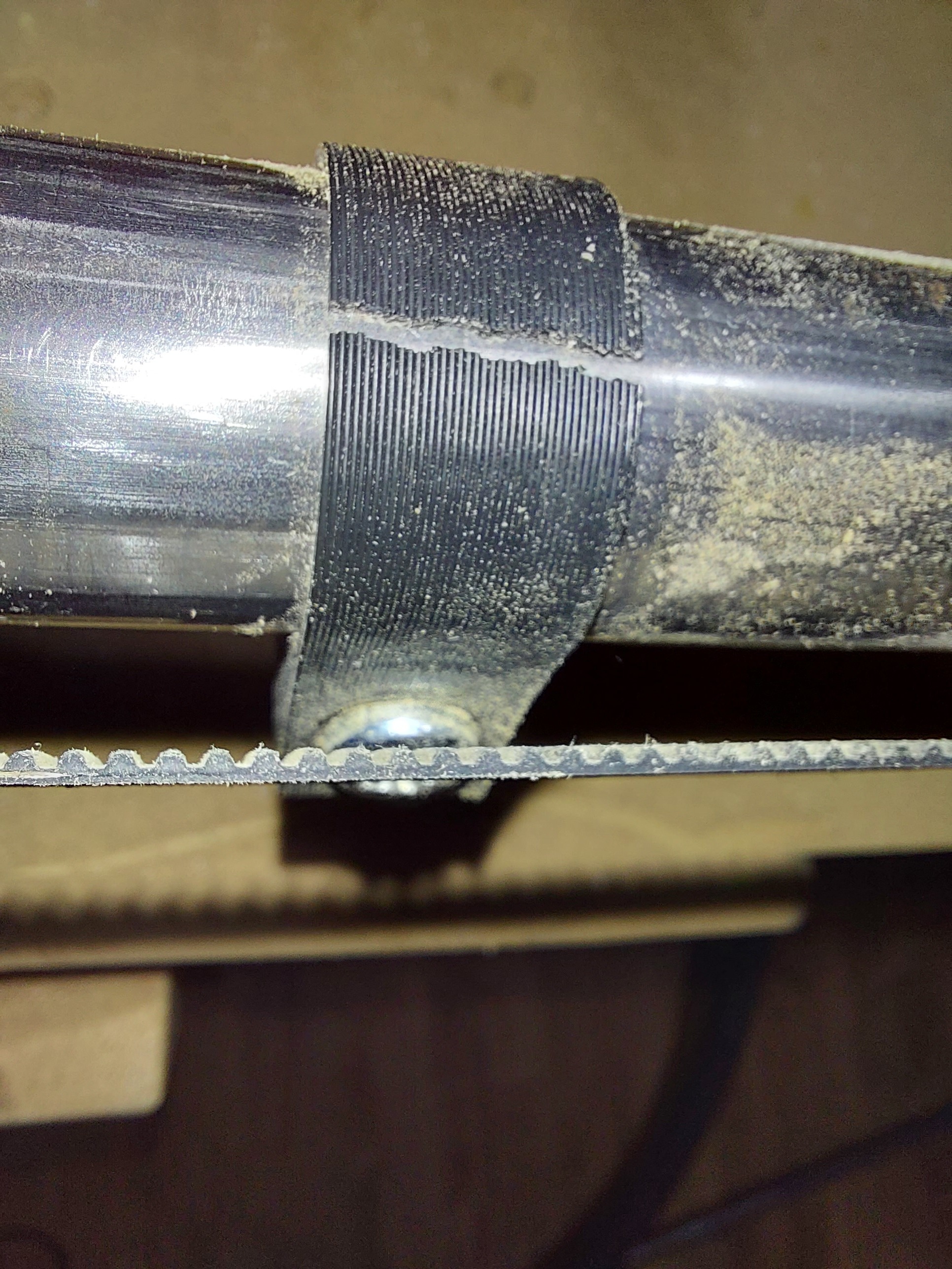
Well, it finally happened. After more than a year of being super careful, I tightened that screw just a half turn too far. It didn’t even break right away, it broke about a half hour into using the machine. I heard a crack and next time I homed, it didn’t find one of the Y stops.
Time to print a new one… I wonder if I have any black left…
1 Like