It started with a pile of leftover 3d printer and MPCNC parts, plus some leftover bits from a “Magnetic Discovery Kit” and me thinking "I can build that from that glass top table.
Ok. Well the pulleys didn’t work. The glass top table doesn’t really have a place to attach the printed pieces, or a lower layer for the sand. It will need a redesign from the bottom up anyway, I think. I’d re-use the glass, but it’s a nice table…
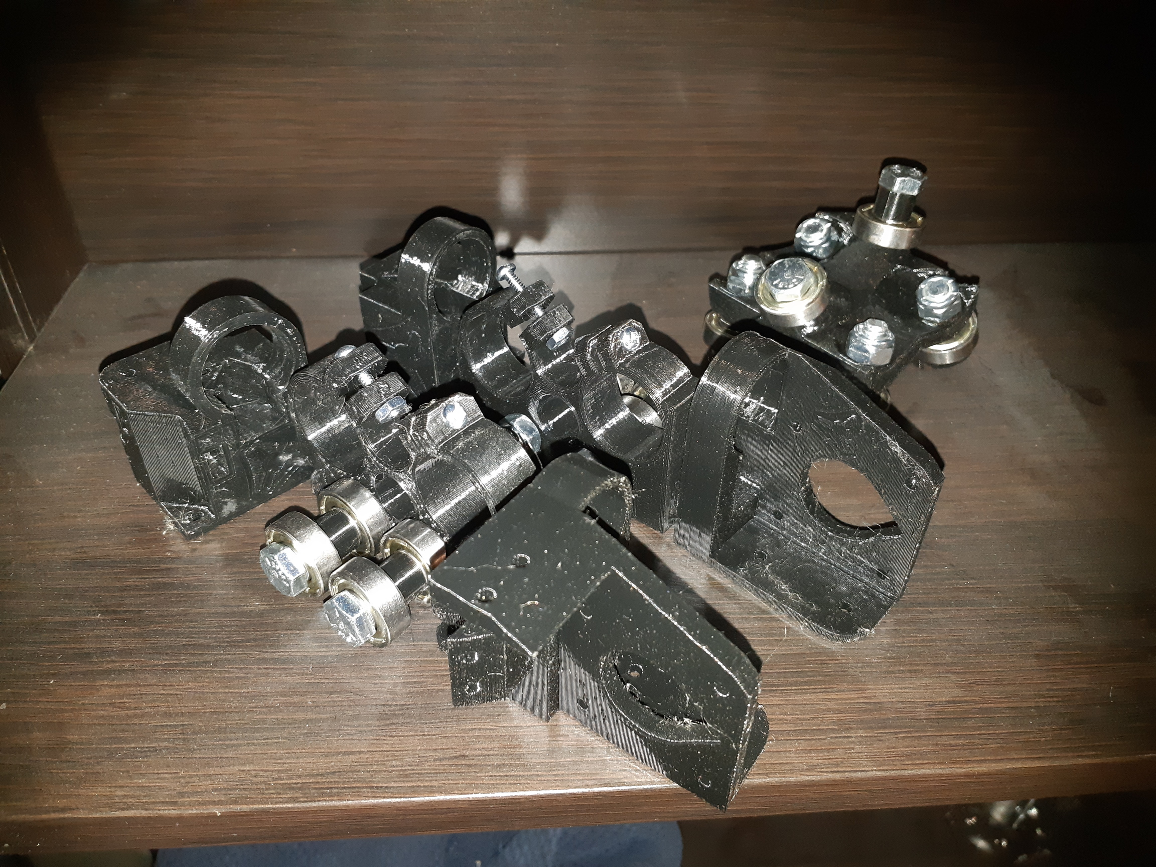
But I have steel. I printed the parts, and bolted the bearings to them. I didn’t have spacers, but they’re ridiculously easy to print, so I did.
Pulleys on the way from Amazon. Much easier to find for 6mm belts. Nema 17 motors from a box. Torque? Current? Dunno. Not even 100% sure they’re 200 steps/revolution. Probably.
Arduino Mega.2560 and RAMPS 1.4 with 4988 drivers from my very first I3 clone. (Which, for the record, was so crappy I am sometimes amazed it didn’t sour me on 3D printing forever.)
My concern so far is noise. Those 4988s are noisy at the best of times, and the bearings on steel aren’t super quiet either.
I will look for suitable glass. I think I have a piece.of tabletop glass from the “as-is” section of IKEA that I can use, about 13" by 16" which I can center in a 22" square LACK Ikea table. There should then be room for the RAMPS board and a power supply in the table,.or at least a 12VDC jack. Maybe a v1pi to run it.
I’m using some TMC2208s on mine and the loudest part is the ball moving through the sand. Won’t break any speed records due to the torque loss of the higher microstepping, but dead silent.
I thought about that, but I’m trying to use up parts that I have, not buy more. Still, if it’s too noisy for the living room, a change may be in order. I’m getting my old Duet Wifi repaired, and while it’s seriously overkill for this project, the network connectivity and the silent drivers might just tip the balance. If I ever get around to building another 3D printer, I might just use a Pi and buy the drivers though. I have more than enough Raspberry Pis around, most of them aren’t being used for anything, and some only get powered up so infrequently that I might as well just keep the SD cards in a box and swap them.
I found a pair of DRV8825s in the parts pile. Only 2, but pretty sure I only need 2. I’ll use those for now. They’re at least better than the A4988s.
I’m not sure that I have an appropriate magnet. I have 1/4" by 1/2" rod, or 1/2" by 1/8" disc. (x3) I think that the 1/2" disc ones will be a netter choice, but they’ll need to be shimmed to get close to the table.
Not sure what kind of surface I’ll find inside the Lack table, I’m thinking that I’ll cut the bottom out and put in some 1/8" dry erase board. I have enough in the garage, I’m sure. This will also space out the bottom of the sand portion, so maybe shorter magnets won’t be as much a hinderance. I may have to slow things down anyway to not lose the ball with this setup.
I had an idea to make the table surface glass Ikea. There is one glass shelf that is almost perfect size… Out of stock in town here though. Looking at another that’s maybe a bit longer than I want, but I think that I can still get the machine to move that far. I might have to change my electronics mounting idea. Maybe not too bad an idea though anyway.
Wow. You’d think that I’d have considered it earlier…
I was looking for a way to mount up the ZenXY hardware to the bottom of my Lack table, and of course cutting it and drilling pilot holes for the plastic parts to mount on can (and SHOULD, damnit!) be done on the MPCNC. All I need are the positions for the mounting holes… Which I can’t find. Weird.
It looks like you can place the parts with the outside edges aligned, and the rails will be parallel to that.
Okay, so measure the STL files and hope that the measurements make sense. Call the left motor corner 0,0. The motor mounts seem to be centered 10mm from the edge. So far so good. I get the one hole 8mm in, okay. The other one is 33… and something. Crap. Well, if I approximate it will probably still be close enough, though this makes my OCD tendancies flare just a little. Still, an approximation here is probably closer than I’d get drilling through the plastic.
Corner mount looks like 39mm in by 5mm and 6mm by 34… and something. Right side mounts seem to mirror those perfectly, as I would expect.
I’d really like to have exact dimensions for the mounting, but I’ll work with what I’ve got… At least I have the dimensions relative to the table area, which is a good start. Like I said, I’d love to be able to just pre-drill my mounting holes and know that I can just pop the pieces on.
Yeah. I wish it was simpler. It seems like it should be, but maybe the CAD isn’t set uo that way. I think it was designed from the inside out, and things like belt loops have squishy dimensions. Sometimes more, sometimes less. I think the calculator is based on the dimensions of an assembled table.
I will say though. It does not have to be that precise. You could easily clamp the part in place, mark the hole centers, and then drill the rest by hand.
I understand and appreciate that. Like I said, it’s my OCD tendencies bugging me. I’ll get over it.
I found another piece of the puzzle, and as it happens, another standard Ikea product, UTRUSTA glass shelf, 61cm by 38cm. I am starting to think that it may be worth doing up some CAD drawings, since buying relatively cheap off-the-shelf standardized parts means that other people might be able to replicate it with good drawings. If they like it, that is.
Unfortunately, my CAD skills are still very much beginner level, and my CAM is still below that. This will be practice. I plan to make my source available so that someone else can duplicate my work if they want.
If nothing else, you have the tools to do it again and you can learn a lot with a good try. I have to get past my own “analysis paralysis” with my table.
So I bought a glass shelf from Ikea. UTRUSTA product 002.656.08 (I think) measured, then used FreeCAD to draw a mock up of the Ikea LACK coffee table product 001.042.91 top. This is the “top” drawing.
I then increased the size of the cutout by 1" (12.7mm all around) added in a 3" by 5" cutout which I’ll be using for a RAMPS stack, 3D printed holder to come later. I measured the STL files for the corners, and added pilot hole markers based on this artwork to position the motor mounts. There is no corresponding artwork for the corners, so I padded it by a few extra mm to be safe. This probably means that hte machine is capable of moving outside of the sandbox on the other end of the rails by a bit, but also means that it’s capable of reaching the other end.
Edit:
I did not leave a power supply or switch provision in this artwork. My power supply can be (And probably should be) surface mounted, and I’ll put the switch in the skirt that I’ll put between the table legs when it’s all assembled.
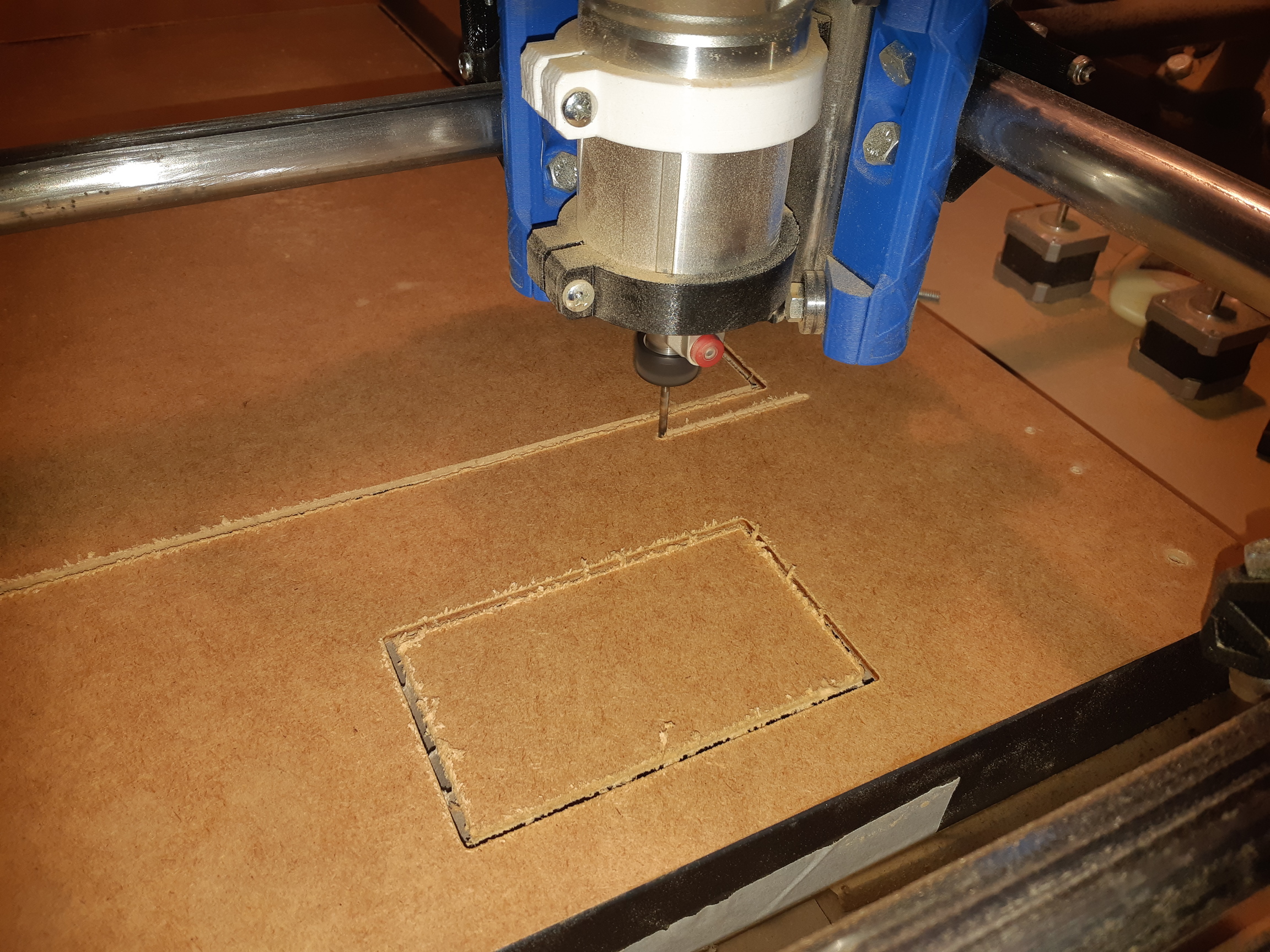
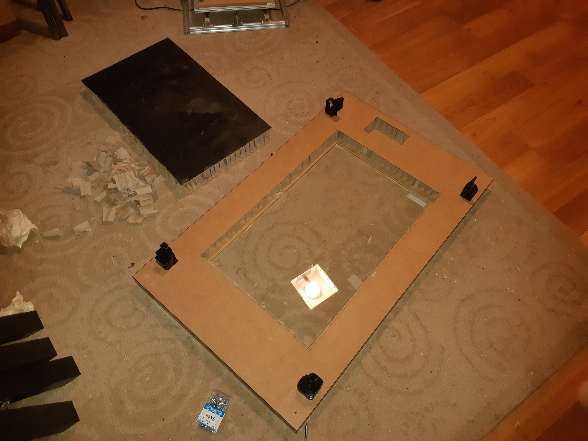
I decided for various reasons to test cut the top art on the bottom first. This also let me triple check that the size was correct for the glass shelf before I wasted $30 buying another coffee table. (Perfect fit.)
Cutting the actual bottom artwork. The inner ring is the position that will be the glass cutout on the top. I did not cut the pilot holes as drawn, just used the center points to drill. They’re drawn 3.5mm diameter, just a bit bit for the #8 screws I intend to use. The 1/8" bit is about right. I suppose I could have drawn it that way, of course.
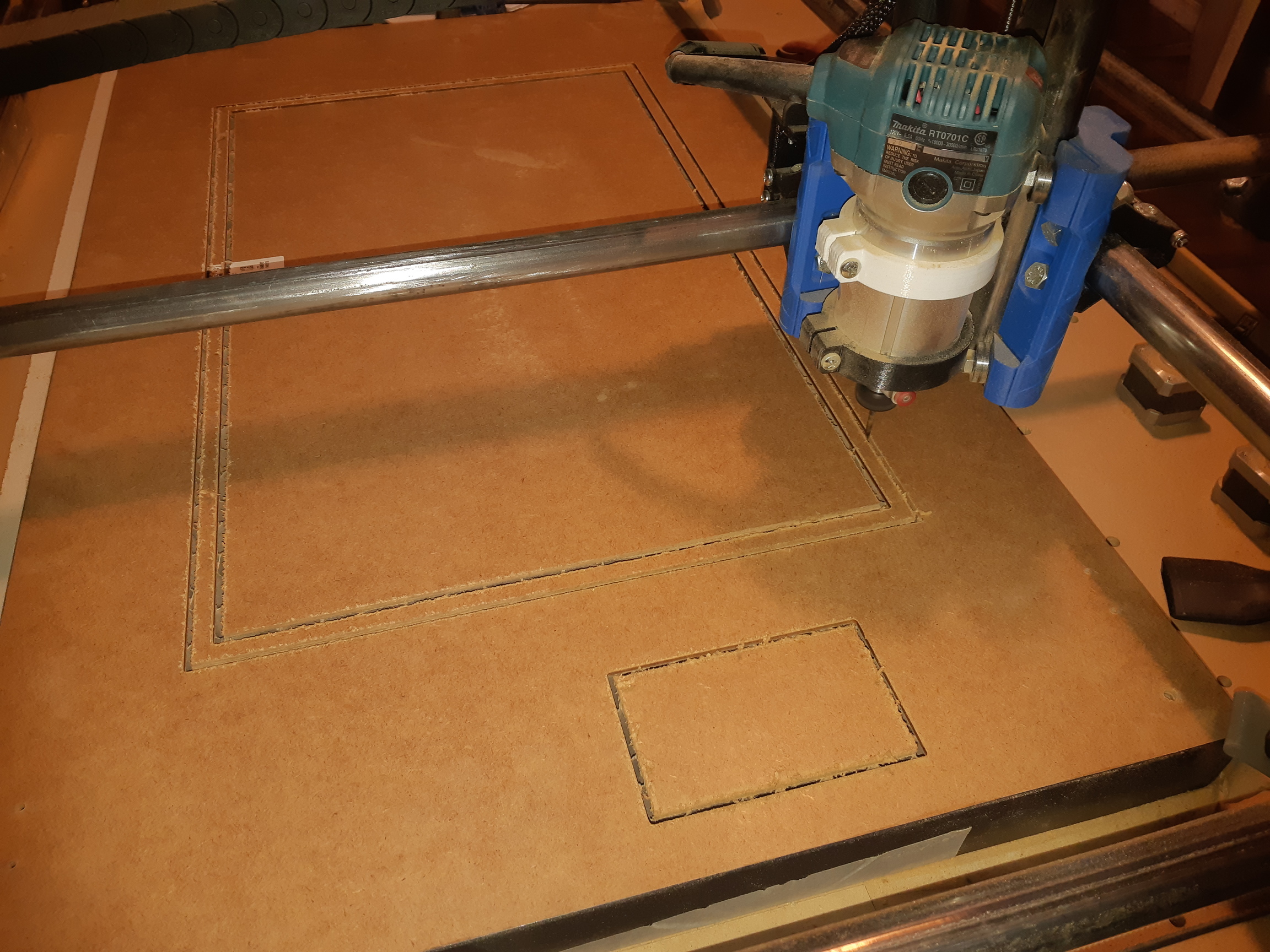
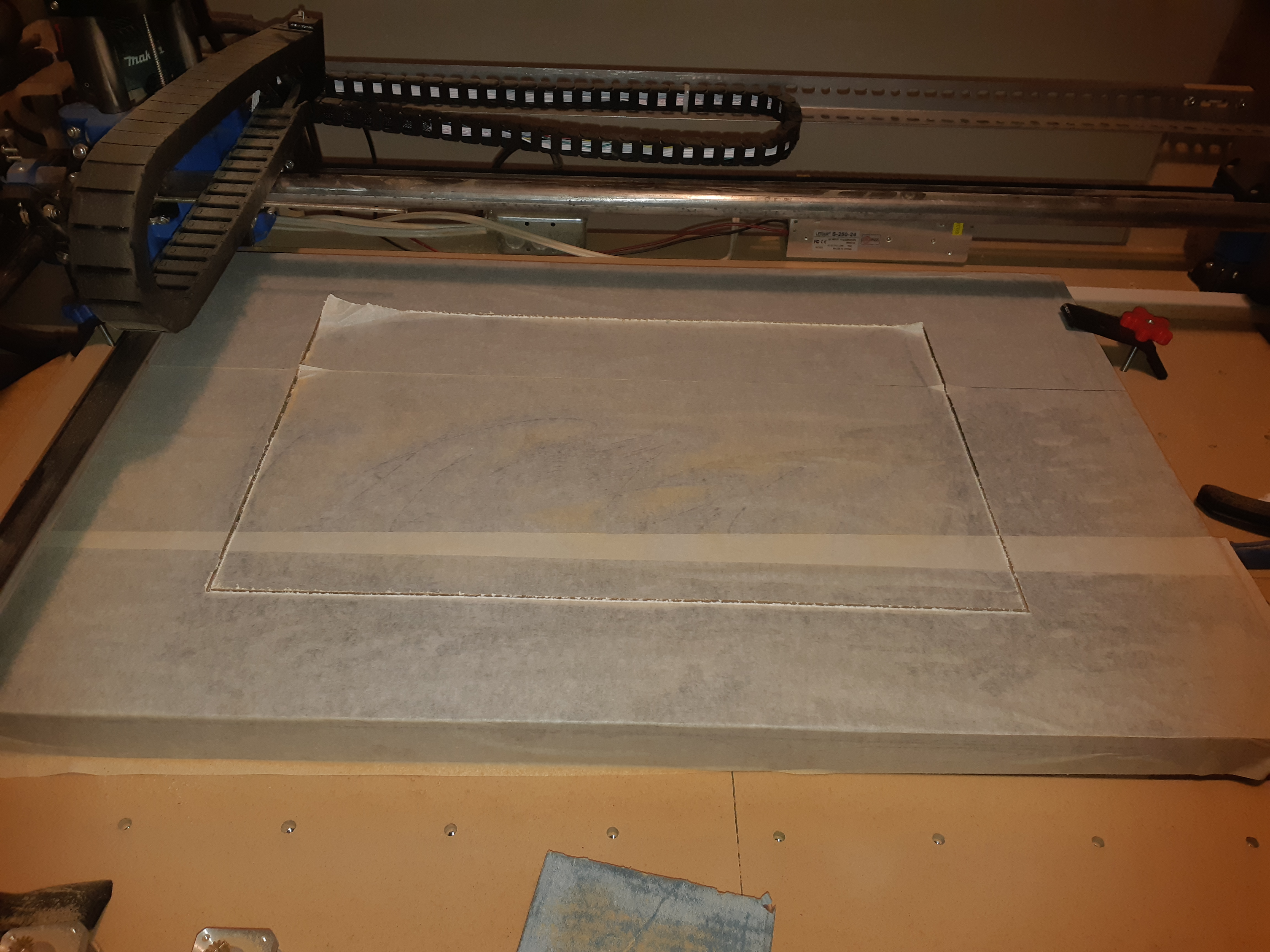
Cutting the top artwork. I covered the table in paper tape. I got it from a friend in the sign industry, it’s to protect the surface from scratches. Kind of a joke since it’s an old table and already has scratches, but I hoped it would help protect the veneer surface at the cut line. I think it did, I only had one very small blemish at the cut line. I’ll hide it with sharpie, <<
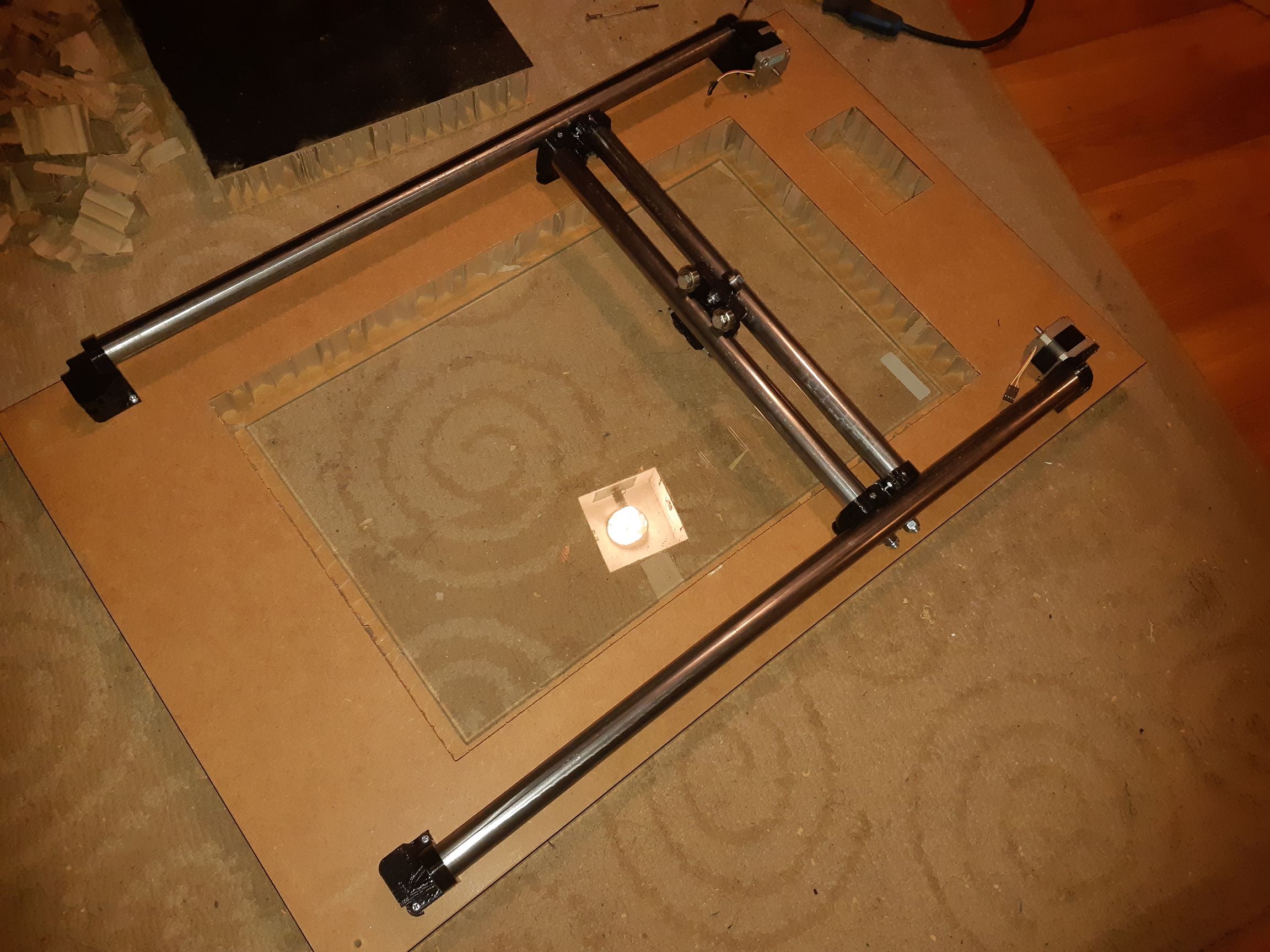
Test fit of the motor mounts and corners. Also test fit the glass in the opening so I could get an idea of the relative thickness.
Next I’ll build the sandbox that will go in the middle of that, and glue to the inside top. It will also support the glass shelf, probably on 3D printed pegs.
I plan on a skirt around the ZenXY mechanism to hide the rails motors and wires. I will leave the USB port available on the Arduino. For now, I’ll use my 2004 LCD controller, and upgrade to the full graphic later.
Amazon order for 16t idlers was supposed to be here yesterday, and still are not, so I’m a bit stalled.
I did test fit the Y rails. My leftover pieces from the MPCNC were perfect. I measured 695mm for length, and I had 2 pieces 1392mm long. Cut one with the hacksaw and boom. Cut X rails from another shorter piece.
Bit of a setback on the electronics front. My RAMPS stack doesn’t power up correctly. Thought I blew D1, but no. It is a trace on the PCB between D1 and the Vin pin. It’s in a tight place, dunno that I can solder it. Might need 5V power for the arduino… or that v1pi. Or dig out another MKS controller. I think I still have one more, my amazon order history says I should have a Gen 1.4 around somewhere. It’s a bit too big for my cutout, might need to expand it.
I measured 3 times, and then cut my X rails about 5mm too short. Fortunately the pieces are forgiving enough to let me.clamp it that way. I do have that extra long piece if need be though.
The bearings on steel are kind of loud. Maybe the stepper drivers arent going to be my biggest concern after all. Maybe it will wear in a little, too.
I still have to build the sandbox. Much as I would love to cnc cut the pieces, it behooves me to remember “right tool for the job,” and the table saw is going to be WAY faster for this job, so that’s what I’ll do.
The box will be 1/2" MDF, and the bottom will be 1/8" marker board. I’ll use RTV to glue and seal it together, with some screws in the MDF frame. This ought to restore a bit on the strength that the tabletop lost when I cut that big chunk out of it. I also plan to leave some channels for lighting in the MDF. I have some 12V LED strips. I may install them, but I was using some for my 3D printer, and after a while they got dim and yellow. They were cheap enough to replace regularly, but I haven’t bothered in the printer, because they’re a pain. I should make replacement easier in this table, I suppose.
The glass shelf should just lift out for maintenance of the sand. I think it’s reasonable to assume gravity will hold it in place if I’m not moving it, in which case the sand ought to be out, as well as the glass and marble.
I wrapped my tubes with 1" heat shrink tubing. The middle tubes wouldn’t fit after that, but the outside ones were bigger offenders. That, and TMC drivers were the two biggest improvements. I think the bottom of the sand tray acting like a drum is probably the loudest part now.
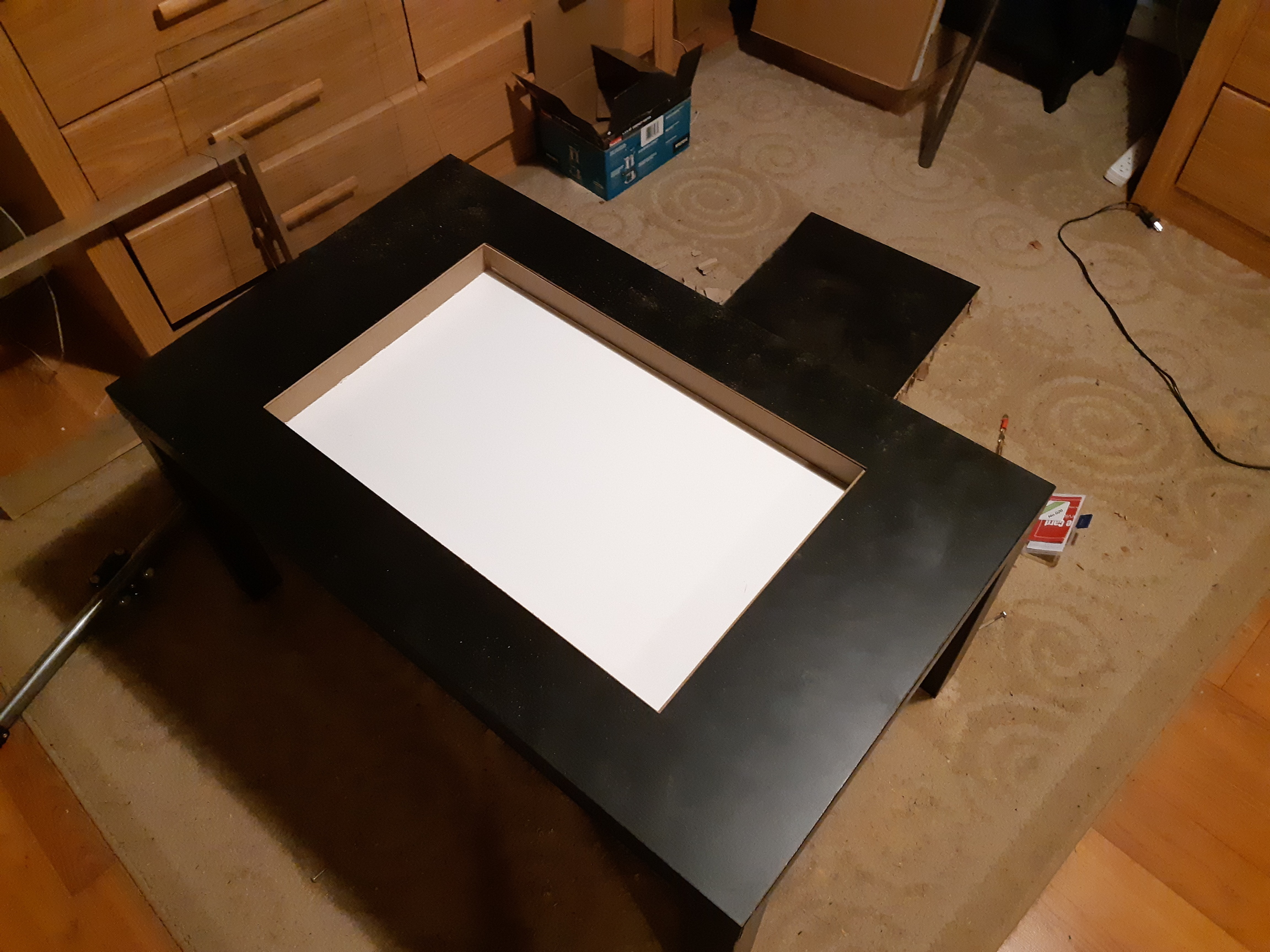
Test fit of sandbox. No screws, no glue, just pushed into place, it stays. The bottom is perfectly flush with the Ikeaboard.
I put it together from 1/2" MDF and 1/8" product listed as “markerboard” I think it’s supposed to be for dry erase markers. Wasn’t sure that glue would hold it, but planning to supplement with silicone caulking, which I’m sure will.
In the X axis, the fit is perfect. In Y it’s out by 1/16" or so. I must have been out by that when I cut the bottom geometry. I think it’s acceptable, but obviously I need to get a better zero marker if I am going to do this double sided cut thing. Or figure out pegs.
Next is to prime and paint the MDF in the sandbox, then apply silicone caulk. I decided to forgo the lighting. I need to leave larger provision for indirect lighting if it’s going to look good. Lights glaring from the sides isn’t very Zen…
Side note. “no more nails” construction adhesive is awful stuff. I was hoping it would let me put the sandbox together without need of screws, but no. There are screws in the bottom of the sandbox holding in the markerboard. I’ll take them out once the silicone is in and reasonably cured, since I think they’ll get in the way of the magnet, though they are technically outside of the area that the magnet should travel, they’re necessarily close to the edges. I also plan on using silicone around the bottom outside of the sandbox to help provide structural support for the missing ikeaboard.
I 3D printed the glass shelf supports in a nice shiny black PETg. I printed 4 corners and 2 sides. Not sure I’m going to use the side ones.
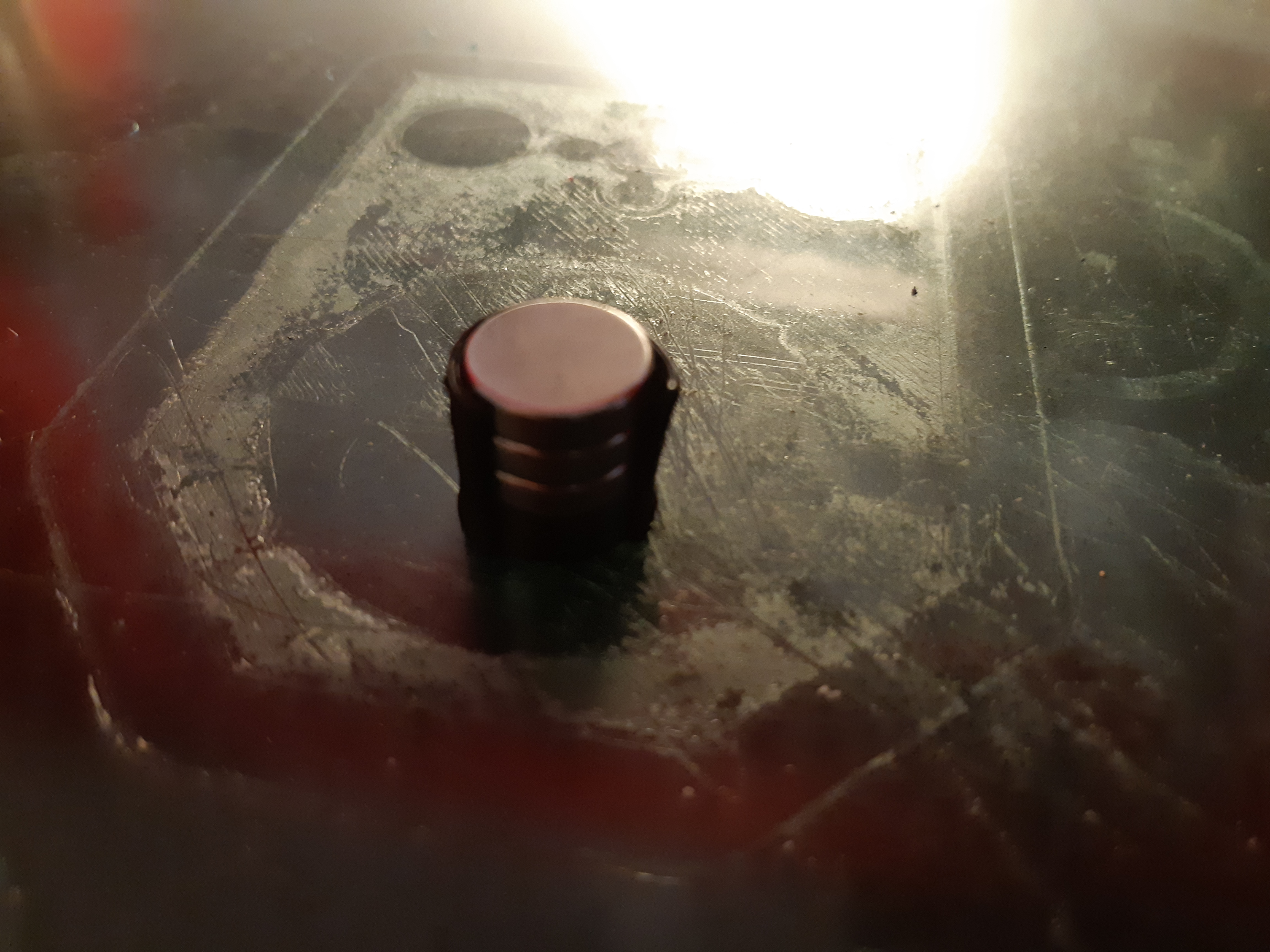
This is as far as I can go tonight. My brushes are all dead, so I can’t prime the sandbox yet, so I installed the shelf supports and magnet.
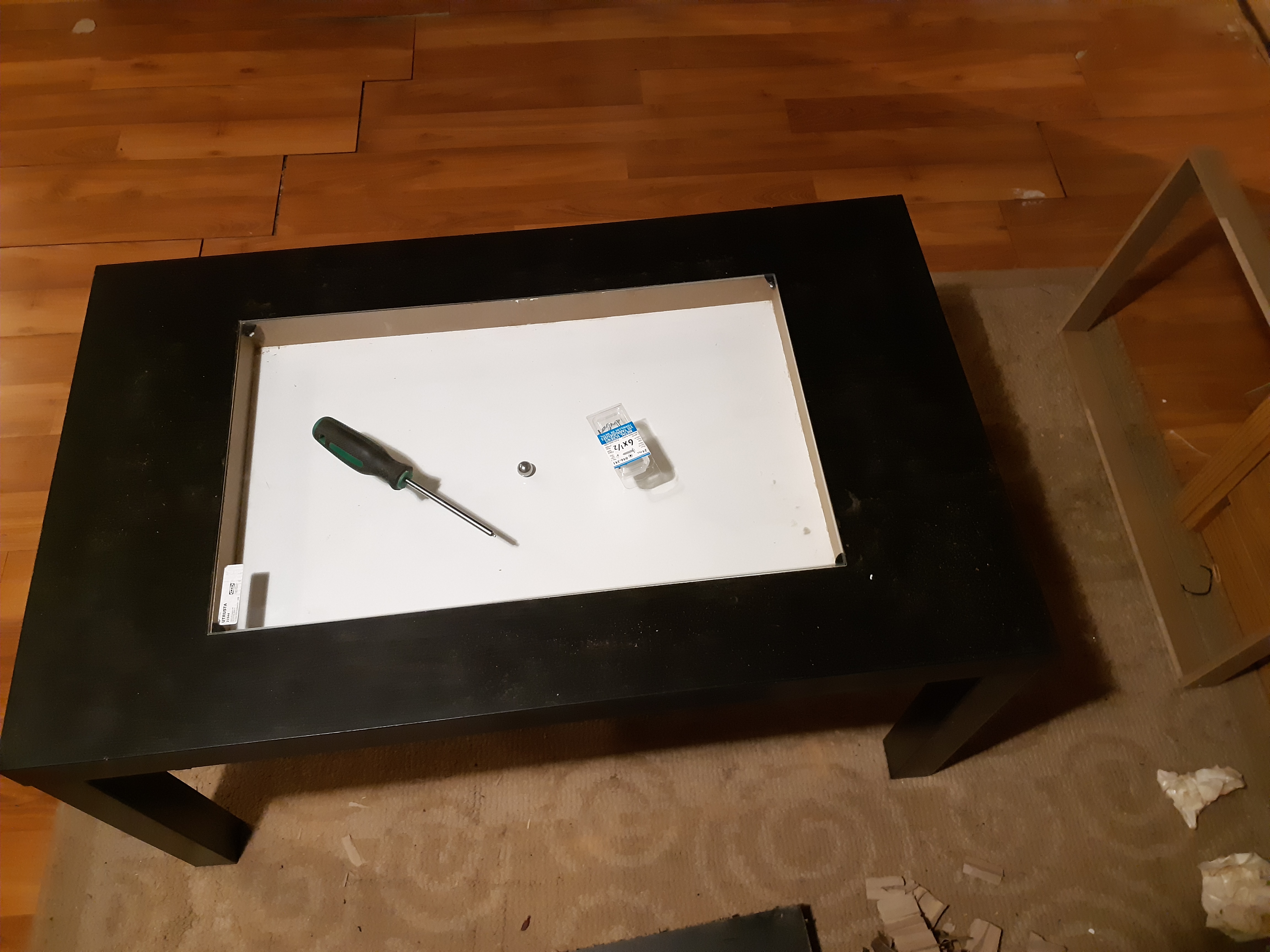
The sticker on the shelf is going to be brutal to remove, like IKEA stickers are wont to be, but it can be done. It sits in there beautifully. Almost like it was made for it.
Turns out that I dont have a 1/2" by 1/2" magnet. I have 3 1/2" by 1/8" magnets. I stacked them, and made a shim/holder for them to bring them to about 1.5mm from the table bottom. I think it will be sufficient, it will hold the ball bearing with the table at any angle up to vertical.
I have been thinking about the paint for the inside. I had intended to paint it black (Cue the Rolling Stones) but I’m kind of digging the high contrast look, and the baking soda will be white anyway. I may make the control panel end white, too.
I notice that I won’t be able to put the side skirts on as originally planned unless I grind down the carriage bolts. They stick out just a bit far. Or… I might talk my sign making friends out of some thin polycarbonate.
I actually redesigned this piece again. Seems I have some time before parts. Stupid Prime day, stuff that I could have reordered yesterday and had today now comes in a week, but I couldn’t cancel my lost order until now.
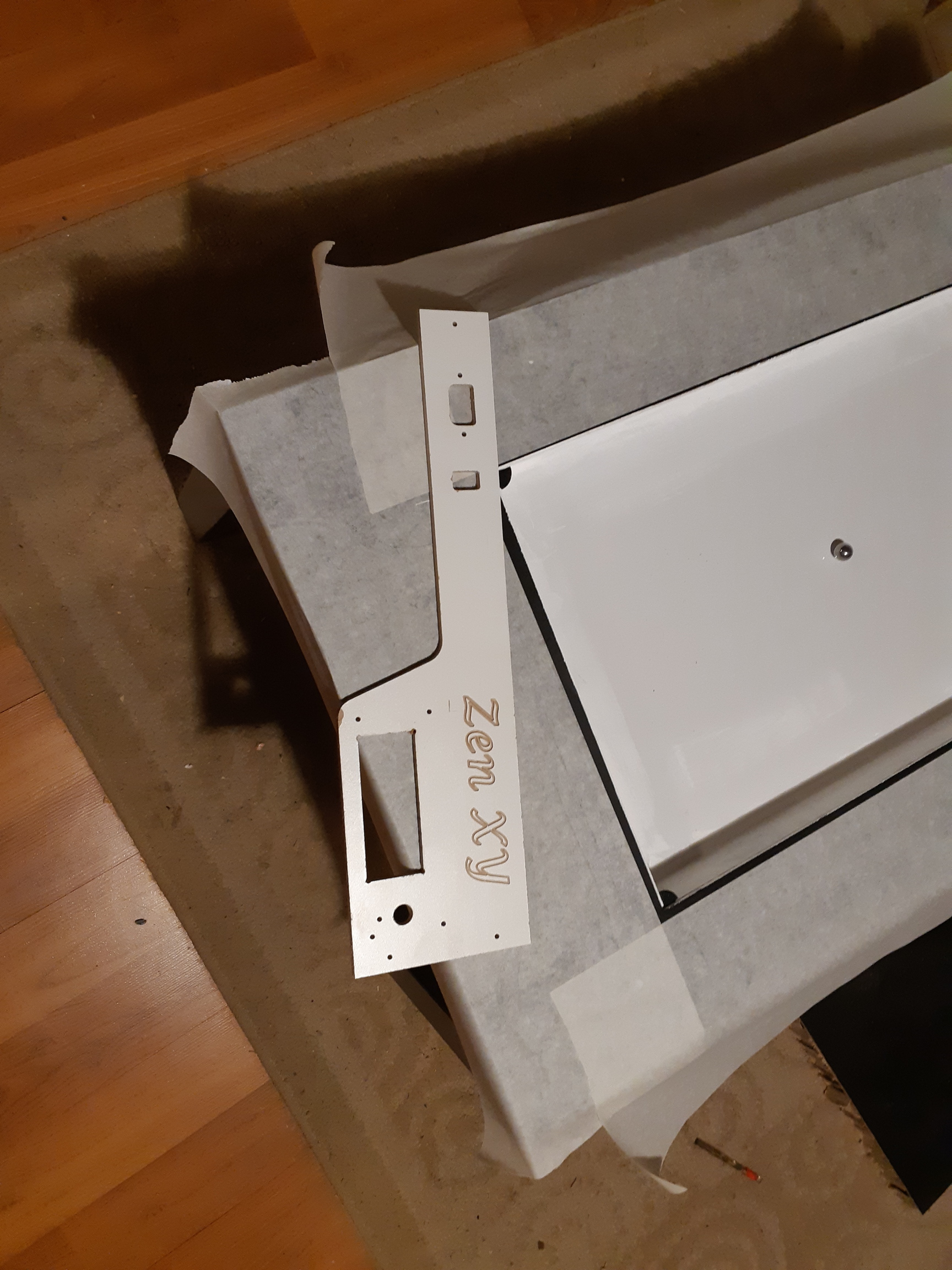
So… I painted the edges gloss white after all. Made the I/O panel from 1/4" melamine coated MDF, but I only had a little. I want to move the 2004 controller closer to center, so I’ll need more material. Also power and switch to the other side.
Gave the text engraving in Estlcam a go, just for fun. Looks pretty good, I think.
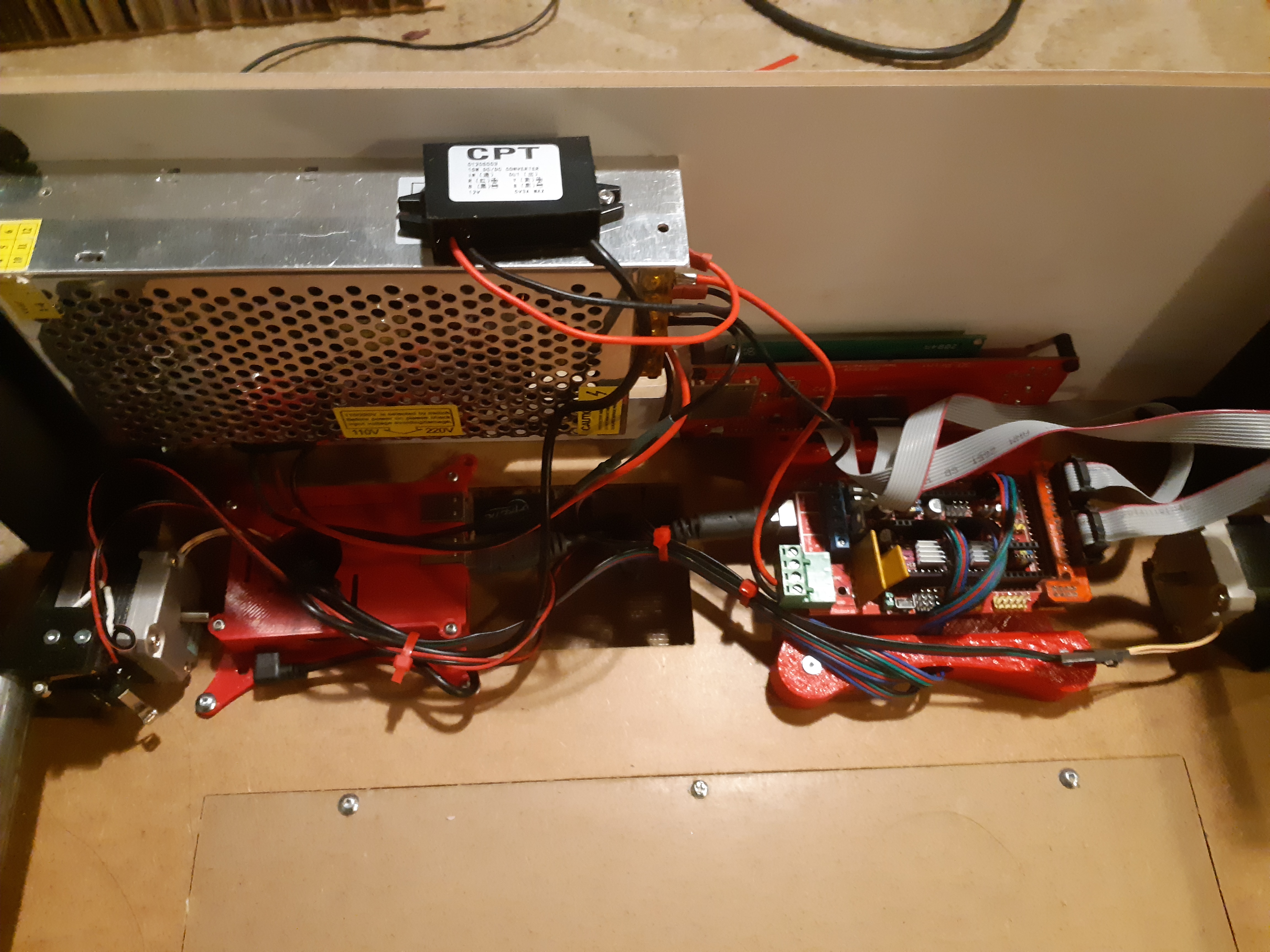
RAMPS stack and v1pi next, I guess since I can’t install belts yet.
Tucked in the wiring. RAMPS stack, 2004 display, and a Pi 3 all connected together. Everything runs from that 12V PSU, I think it’s 360W. More than enough power.
And the face. I could have done better on the alignment. Not convinced with visible screws. I’d almost rather go full steampunk with black and copper. Maybe next project, but this isn’t supposed to be the pretty end. This should be the end close to the wall (where the power is.) Edit: the hole next to the LCD is for access to the SD card, but maybe with the v1pi in there I dont need it.
I have been having trouble getting good information on which endstops are which, and which motor is which. I assume I’ll be changing them up at some point. The switches should be okay screwed in where they are at least. It’s easy enough to figure out X from Y endstops. I assumed that the motor with the stops is the alpha motor, plugged into the X drive. I might need to reverse motor directions, of course.
I’ll need to remove the corner pieces when my pulleys finally arrive. What a nightmare. First, my order which should have arrived Oct 10 gets lost. “Please wait 3 days. It might just be late.” Oct 14 is Prime day, and nothing ships in less than a week. Ugh. Oct 14 though, overnight shipping is a thing again. Oct 15, package on the doorstep… same pulleys I already have. The ones that don’t fit. At some point, Amazon recognized that I was buying something very similar to something I’d bought before, and suggested that I might want the same thing. I must have clicked OK. Today, those ones aren’t in stock. Different ones are, but ship for Monday. $8 extra to have them next day. I suppose technically today, now. I paid the extra, and triple checked that they are the ones I want, 13mm flange diameter. I’d better get the right ones this time, and they’d better not get lost or be late. Running the belt should be all that’s left.to do.
This project is nearing completion. Just waiting on those final parts.
Can you print some pulleys to see it move? I would be thinking stuff like that.
The motors are funky. It is kind of tricky to determine which motor to flip when they aren’t moving correctly.
The endstop that is angled is the X and the one that will hit the truck is the Y. It needs to home Y then X. If it isn’t at Y=0, The X won’t home. So you also want to make sure you don’t have a Y bump.
I should have my pulleys in the next 3 hours, says the courier. So long as they’re the right ones…
I didn’t think that printed pulleys would be any good, but I suppose that they’d be okay for the accuracy that this would require.
I placed the endstop switches based on remembering “Y homes before X” and the description of the long rails as the Y axis. In the SomeOldGuyCoding video, I think he has it backwards, which planted a bit of doubt, but I also remember that his first attempt to auto home failed, because it tried X first. (I think he called it Y though.)
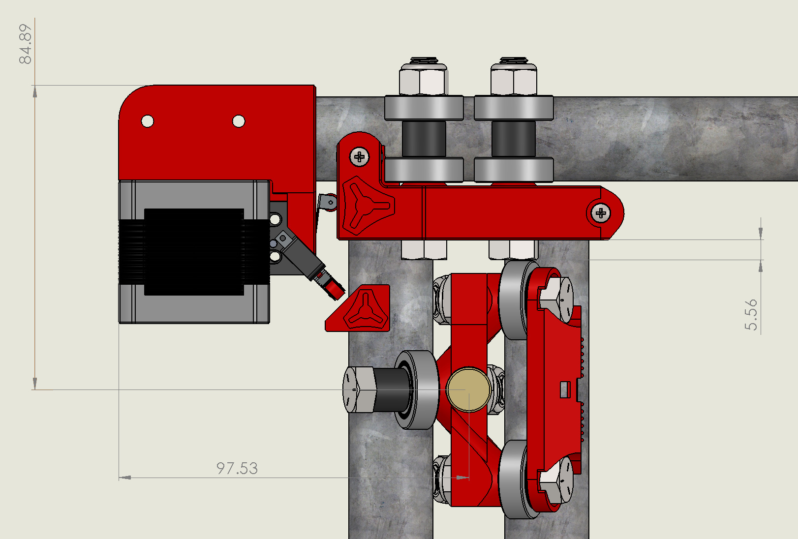
I’ve been playing with Sandify, too. My table is 352.5mm by 572.5mm. Given that the bearing is 1/2" in diameter, that gives me an addressable area of 340mm by 560mm that I plugged into sandify. (Okay, it should be 339.8 and 559.8 being technical, but I think my bearing is a trifle undersized.)
When I was working on it last night, I had the table upside down on the carpet, and the bearing stayed in the table. I guess my magnets are strong enough.
Okay… just received email from Amazon “We encountered a delay in shipping your order…”
Pulleys seem easy enough to print… Looks like 9.5mm rolling diameter by 8.5mm height, 3mm axle. I’ll probably make the flanges short so that I don’t have to print supports.


 <<
<<


