I’m guessing they will be… Not great. But good enough for a while.
So my pulleys showed up just as the printer was finishing.
X and Y axes move correctly as commanded, but the homing switches are acting reversed. They are plugged in correctly, wired to normally closed. My multimeter confirms correct wiring, and they are correctly connected, but the firmware reads them as triggered when released and triggered when closed.
It seems to skip steps about 2" short of Y max for some reason. I’m checking for mechanical jams, but it moved smoothly without the belts.
That’s the other benefit of printing them ![]()
Always triggered… Can you unplug the endstop and carefully short the g and s pins while checking with M119? I test with a jumper. They should register as open when jumpered.
Keeping it square with all the belts can be tricky.
It’s square, At least as square as my framing square is.
The configuration.h file had the logic for the X and Y endstops inverted. I downloaded the 507 version, and only had changed the machine name, table size, and enabled the 2004 controller. now I have turned off the inverted endstop logic. I’m compiling and uploading the revised sketch now. this is on my ancient laptop, so it takes a while to compile… Zzzzzzzz
I confirmed by holding down the switches and then telling it to auto home. It moved until I let go of the switch. I’m hoping that it’s a simple mechanical jam causing missed steps, or just improper homing. It moves freely when I do it by hand…
Okay, compiled and uploaded. I need to adjust the X home position, it’s a couple teeth off, but changing the configuration.h was what it needed. The missing steps seems to be friction when the quarter twists in the belt get too close tot he edges. Might be an issue with my printer’s bridging, I could have been extruding too hot. I can hear a ticking noise from one corner as it moves normally, but it doesn’t like being close to either end of the Y axis, where the twist between horizontal and vertical has to be sharpest, that’s where it misses steps. I have a short video of it getting cranky YouTube Video the reasons are different, but it does it without crashing into the ends at the low end of the Y axis as well. In the video, it’s trying to run past the Y endstop because it never made it to the other end of the table, but it doesn’t like the low end of the axis either.
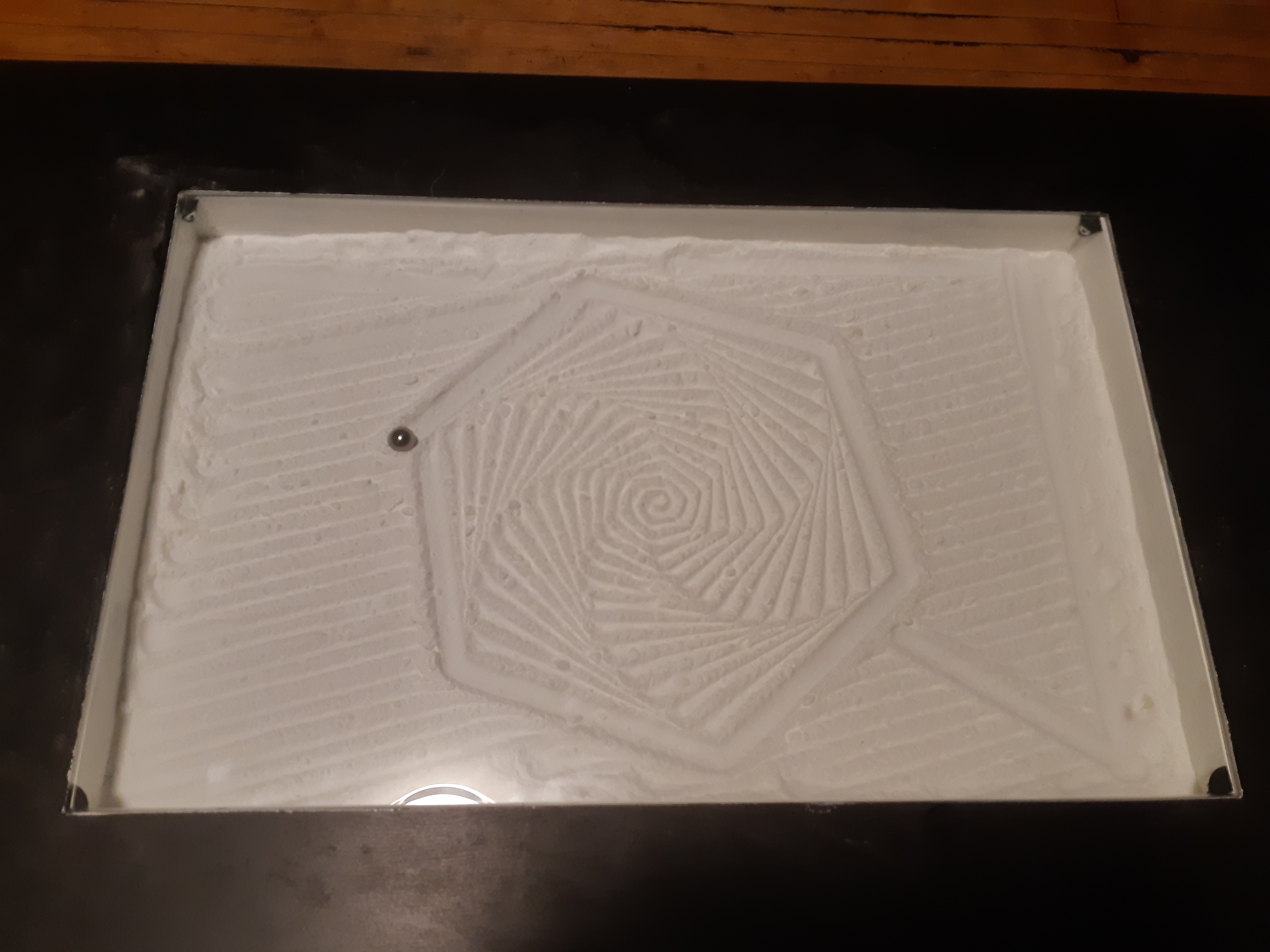
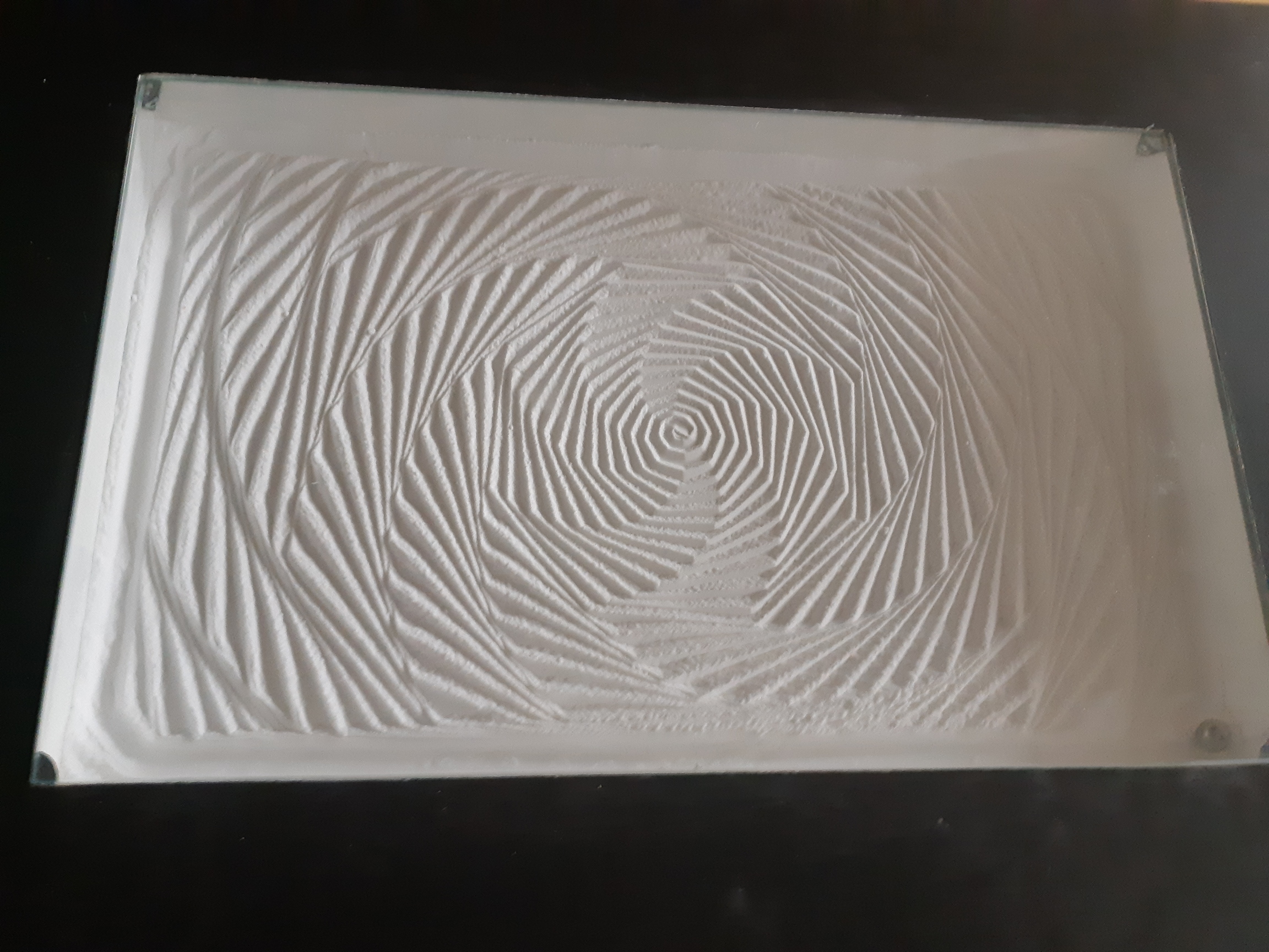
I have it spinning the ball around in circles at the center of the table, and it works perfectly now (Spiral wipe code) The screws around the outside in the bottom are causing grief, too.
1 Like
Its moving! Looks cool.
Can you increase the current to that motor? Check the wiring and the grub screws?
So rarely has “MOAR POWAA” been the solution to any kind of mechanical issue that I’ve ever had that I tend to over discount it. Well, except when it’s my car, and more power is ultimately the goal, but even then, brute force isn’t my general approach.
I had the current set on these mystery unknown motors set to a super conservative 350mA. It just so happened that more power is what they needed to stop skipping steps randomly.
At 1.2A, one of the motors stopped moving entirely. Well, they were cheap mystery motors, I shouldn’t really be that surprised. On that motor, both coils read as open circuit. No two pins connect to each other anymore. The other one still seems to be okay. I replaced the dead one with one that I had been using on a bench. It used to be in my I3 extruder, and at some point the wiring harness got melted. I put a compatable plug on (I had the wires insulated and separated with hot glue where the heating element wires had melted everything together. I was using the motor on a test bench where it didn’t really matter that the wiring was a mess. I had almost exactly enough good wire from the motor to match the wiring harness on the mystery motors, so… All good.
Running at 1100mA no more random skipped steps, but it sure is louder than it was. This is going to be decor for my mother, and she doesn’t hear quite so well any more, so it’ll be fine. Still, quieter would be nice. I’ll probably turn the current down until it stops behaving badly.
I think I have too much baking soda in the tray. It loses the ball at about Y=10, and a few other places. About 1/4 of the ball diameter for depth? I might be running closer to 1/2, probably too much for my poor little magnet.
Edit: it’s nearly 3:30 AM, that’s enough tuning for tonight. Still running too much power, the motors get quite warm.
3 Likes
There is a big difference between 350mA and 1100mA. I have found it is pretty sensitive to the current and there is a noticeable difference between 750mA and, 700mA. I’m sure you’ve got a setting that will work.
Looks good though. I like the sharp contrast between the black and white.
I keep feeling that something is wrong, and probably my mystery motors.
At 1100mA it works – mostly. I know that it won’t take 1200mA – at least its counter part did not. I tried a web design, and it starts skipping steps again. The wiper works pretty well, but anything complicated and it’s anyone’s bet. Sometimes, it’s working fine, then starts chunking away randomly. It’s really getting on my nerves.
I’ve got a couple of new motors, and I’ll be heading out to Lee Valey tools tomorrow for magnets, since the stack of 3 that I’m using keep dropping the ball. I’ll try adding one more to the stack, since they don’t have one 1/2" by 1/2" magnet to replace it with. They have 1/2" diameter by 1/8" thick ones. Currently I’m using 3 of these. I’ll try adding another one. It might drag on the bottom, there’s about a 3mm gap, now. (I thought I had it shimmed closer) It looks like the only shot that I’ll have to replace the whole stack is to remove the belts so that I can pull the carriage out.
Maybe drop the acceleration? I personally like the acel really low. I find it more aesthetically pleasing.
yeah, reducing accel is on the list.
I did manage to add a magnet to the stack, and it doesn’t drag, so there was probab y a 3.5mm gap before. I seem to have miscalculated homing positions, I placed things so that the centre of the magnet goes to the edge of the table, when it needs to be a quarter of an inch into the table. Funny, I remembered that in defining the max limits. Sandify does have the minimum positions as well, so I’ll set those to 6.5mm, which should do the trick.
When cold, the motors don’t skip steps. Once warm, they’re pretty bad. Or maybe the drivers are getting too hot. Fans are more noise, but it’s a pretty small amount at this point.
1 Like
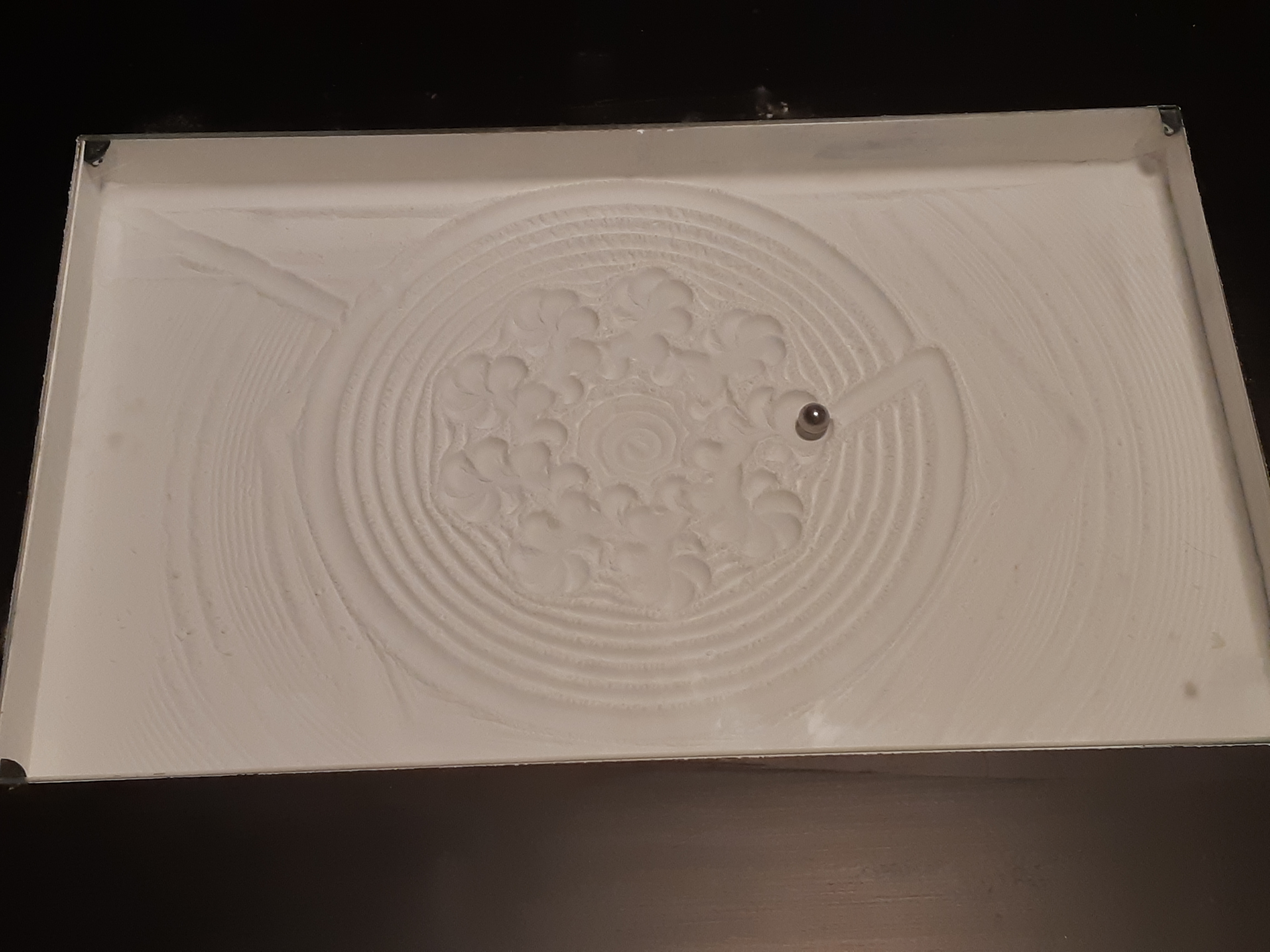
Sandify space filler, now that I’ve stopped losing the ball so much. I’ll have to change the end plate again, but that’s no big deal. I’ve got another full graphic controller coming, so getting rid of the 2004 controller. Also, a smaller PSU. Don’t need 360W, I’ve got a 12V/5A PSU coming too, much smaller, so it doesnt use the same mounts.
So much for using leftover or spare parts… but I think the end result looks pretty good, even if you can still see the rails. Glad I didn’t use bright colours for the printed pieces (though the v1pi case is raspberry red. You can’t see it normally.)
This might need some fine tuning, I may end up making a new top for the table to correct some distancing issues, and add LED lighting.
1 Like
Something ain’t right here…
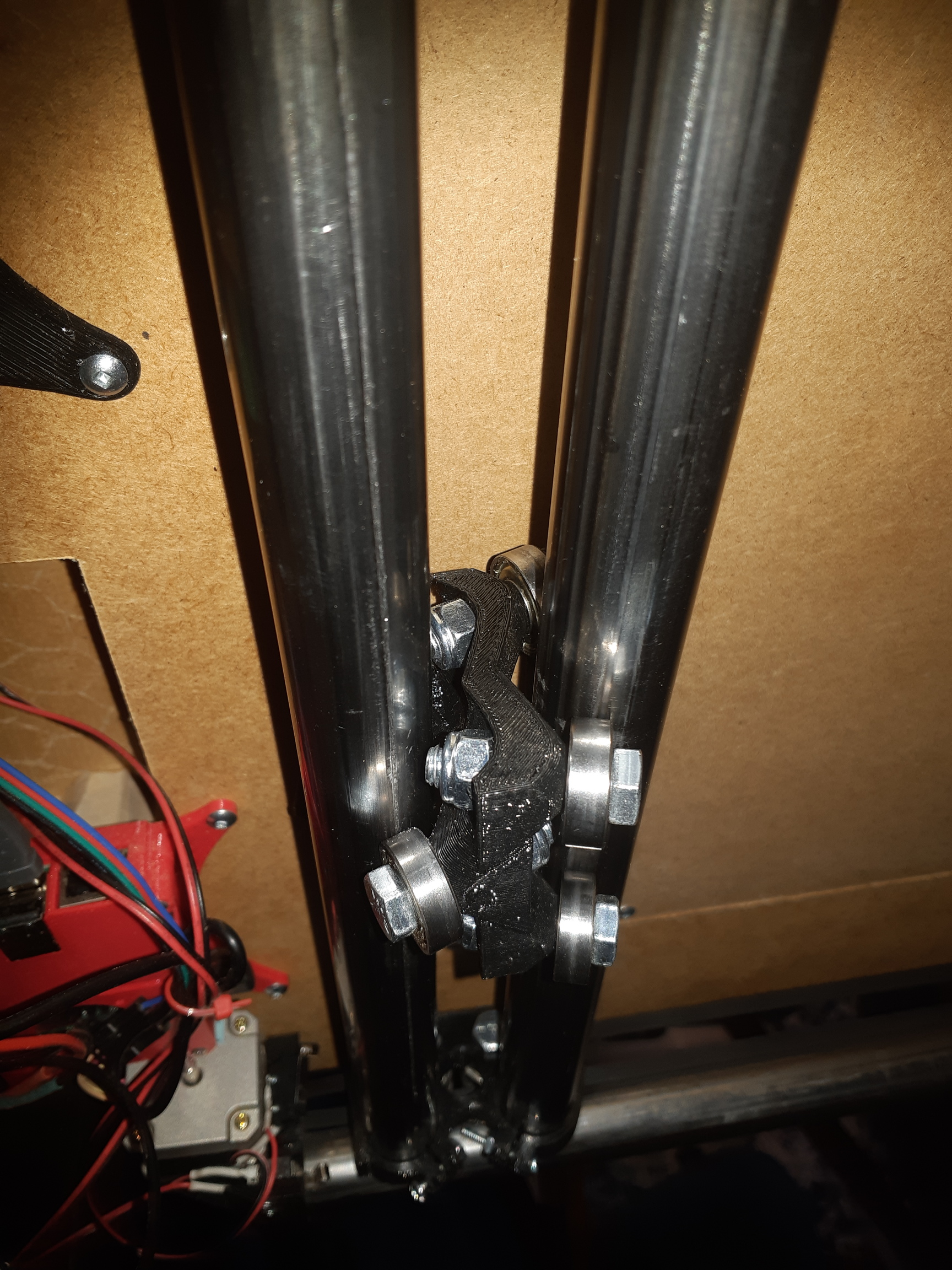
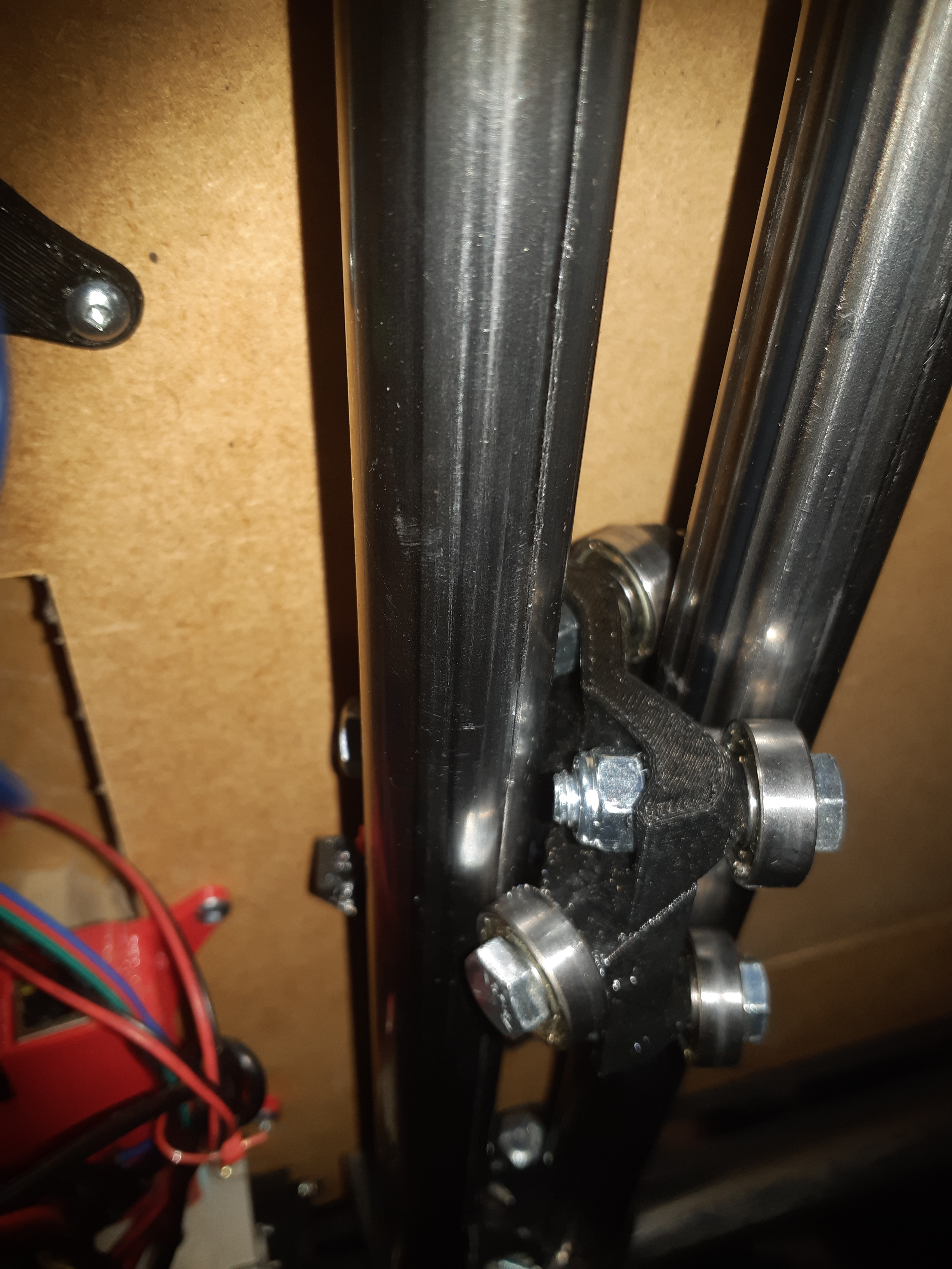
Trying to diagnose the skipped steps. It looks like something happens to the center shuttle, and it gets pulled.out of alignment. I was under the table, and noticed that there is a ridge gouged into the steel tube along the side where the single bearing rises. There is another along the top that I van feel with my fingertips. This is pretty obviously a problem, which causes the machine to need too much power, thus the skipping steps.
Did I put the part in wrong? The long bolt where the belts are zip tied is facing towards the motors, along with the idler pulleys which are offset from the center of the trucks. It seems to fit correctly. I’m actually almost ready to go buy some 3/4" conduit and print new parts to see if that version works, but I don’t want to give in just yet.
The center piece seems to be able to yaw in between the rails, which I believe is the problem. It fit tightly when first installed, but now some bearings don’t seem to make contact sometimes.
I’m inclined to think this means I assembled something wrong.
I know that it was tight when I first assembled everything. Now… not.
So maybe PETg is just too flexible, or somehow the stresses from earlier distorted it. I printed another center, using the same printer gcode that I used before, and verified that it’s nice and tight with the new piece.
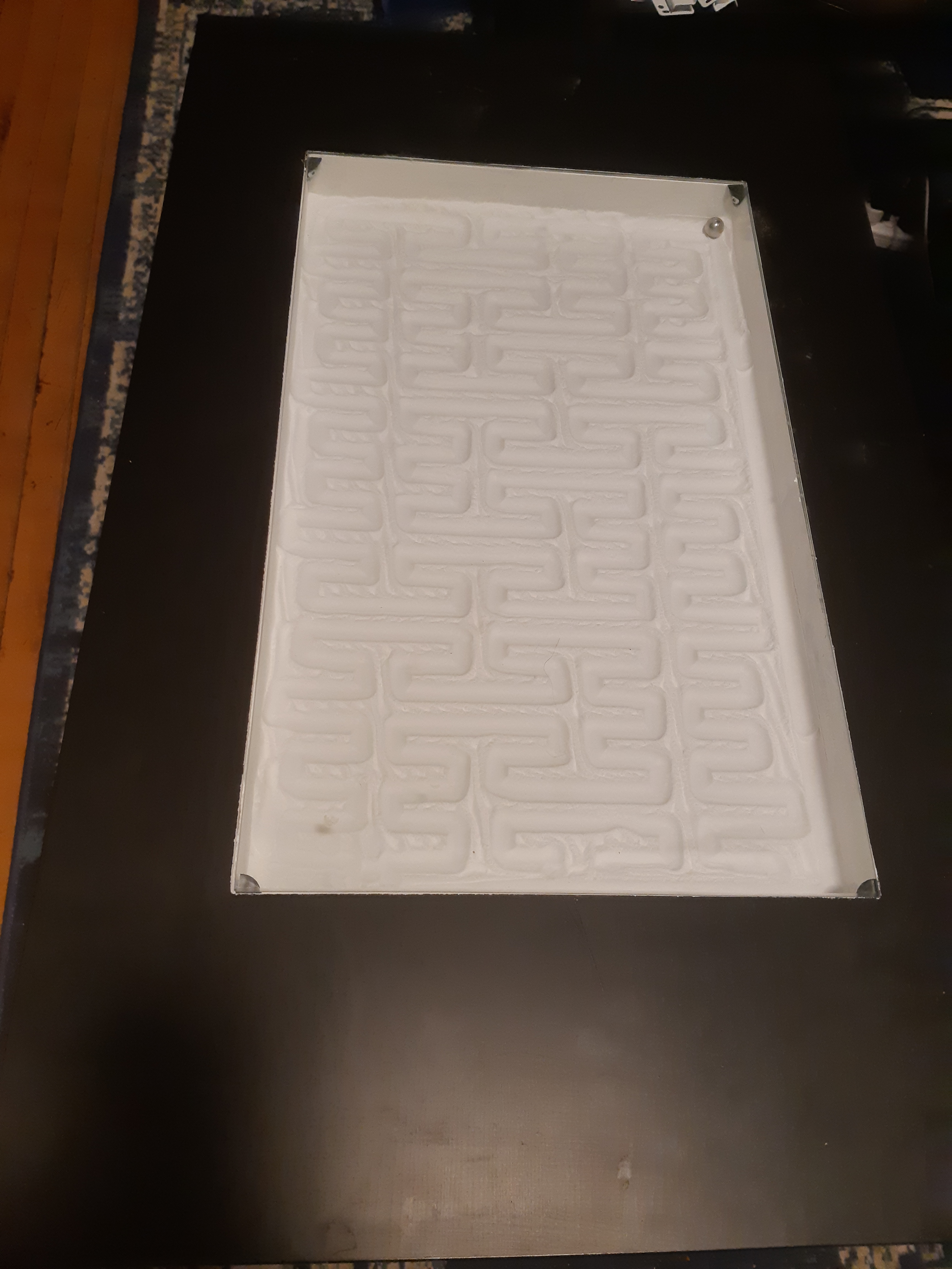
Then I broke out the 3 year old bright yellow PLA that I have left over and printed another one using the old printer and reassembled. This way, if it is the PETg, I won’t be seeing the same problem next week. Tried it out printing a pattern that I never managed to finish before.
Nothing proved yet, but it did finish. I didn’t think that the plastic would disort that far. Maybe from when it was skipping steps for other reasons it hammered the 5/16" bolts into the plastic? Dunno…
Edit: Now I seem to be having a lot of trouble with homing. The X stop on the belt doesn’t want to contact the switch anymore. I’ll try re-doing the zip ties, I must have the angle wrong.
Re-did the zip ties, made sure that the block on the belt is turned towards the homing switch, which seems to do the trick. There are times when it seems like something is taking more power than it should, or maybe that’s just the noise from the steppers. It’s hard to tell, it seems to move as commanded, so it can’t be just slowing down, since the program isn’t going to wait for the steppers to catch up.
1 Like
So far so good, the center seems to have remained tight.
The second mystery stepper burned out at 900mA. I managed to turn the current down. I have a couple of good 84 oz-in motors in now. I also added noise dampers, which help more than I’d have believed. The motors arent getting more than warm now.
I replaced the 360W PSU with a 60W one. Much smaller. I’ll have to change the end board where it mounts, but also have a full graphic controller coming, so I’ll swap that when I remove the 2004 controller. I’ve got the CAM done for it, I just need to give the CNC a piece of melamine to do it.
Assuming that the center doesn’t go loose again, almost done. I don’t know what I’ll do if it does go loose. Maybe fit in a linear guide…
3 Likes
Started getting crackling noises from it again. https://www.youtube.com/watch?v=ATkncKRLZLE
It seems to still be tight, but I can hear it trying to turn and scrape along the edge of the bearing again. Something just ain’t right…
While your accelerations are low those speeds are much much higher than I run.
I am going to start this with…I am working on a new version but it is tricky.
The zen is very sensitive to magnet and ball distance, that also means the surface nearest the magnet needs to be super flat and level for the ball to stick, and the magnet not to bind…but be as close as possible to the surface. I shim mine with paper. magnet strength is cube root of the distance (if I remember right so serious ever tiny bit helps.
The other part is the bearings on the rollers is super sensitive and the rails need to be perfectly parallel and start perfectly perpendicular. If this is off it will raise the magnet up and bind, hearing it clicking is a sign of this happening. This is the part I am working on. Gravity is not the best helper here, the rail needs to be fully captured.
That center problem you are having is bugging me, I don’t think something is right there. Any way to sneak a picture of the top single bearing where the zip ties connect, maybe that stack is backwards?