Since finishing my MPCNC, I always wanted to add a laser diode engraver/cutter to it. However, I wasn’t able to find one with a good ratio between performance, reliability and cost. So after a bit of back and forth I decided to try building my own.
I wanted to take this opportunity to not go with the usual hobbyist laser diode engraver design, but instead add something that is mostly found in the more expensive versions for industrial applications: a beam correction. Laser diodes, especially the ones with a high power output, have a fairly bad beam quality and there are quite a few ways to do a beam correction with different advantages and disadvantages. I am going with the use of an anamorphic prism pair. This doesn’t correct all the optical aberrations of a laser beam, but its fairly simple to integrate and effective: I have seen laser diodes with rather low power (~6W) being able to engrave stainless steel thanks to a prism-based beam correction, so that is definitely a goal of this project.
Such a prism pair basically takes the elliptical beam of a laser diode and transforms it into a circular one by expanding the beam in one direction. This way, for example, the elliptical shape of a laser pointer spot can be circularized. The effect of the prisms in a laser engraver is a bit more complicated, but instead of going through the theory I will just show you the results later.
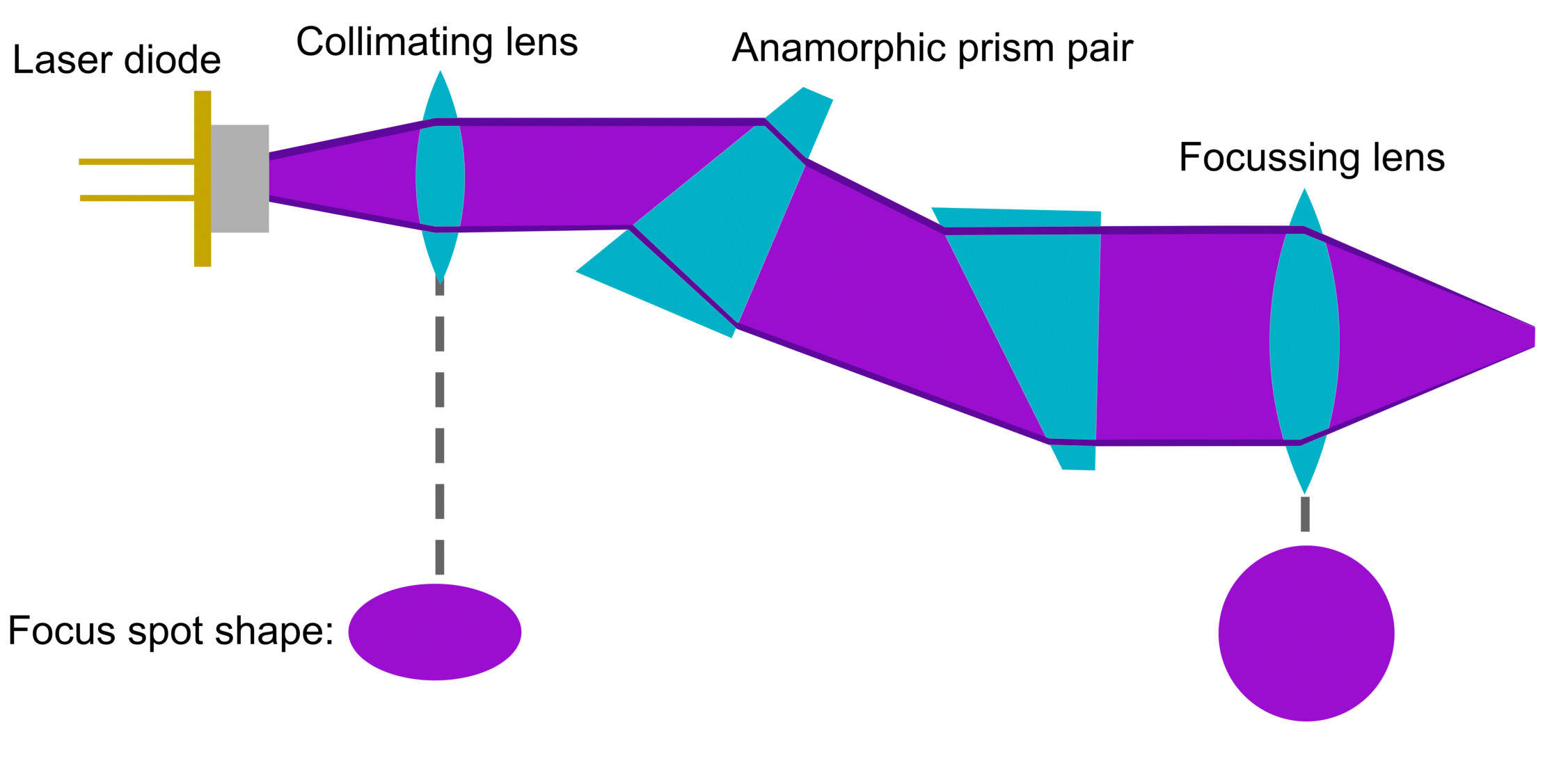
The sketch above shows the beam path and all the necessary components. In order for the prisms to do their job correctly, the laser beam has to be collimated, so one needs a collimating lens right behind the laser diode. Then the beam is passed through the prisms and focused by a focusing lens.
By the way, the process of collimating and focusing the laser beam with two lenses is also generally a better way to achieve a good and consistent focus spot compared to the single lens designs (G2, G7, …) most of the common laser engravers use.
Now to my laser design:
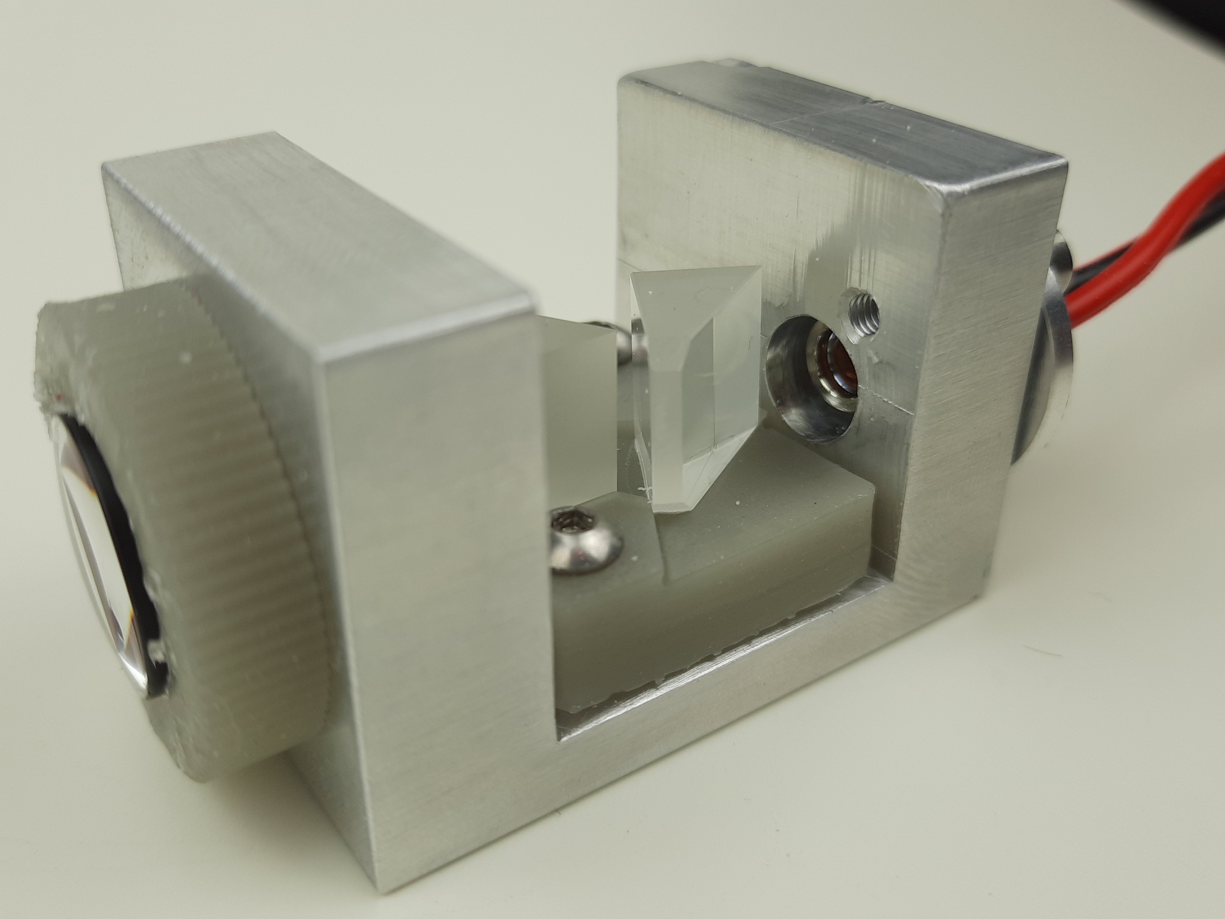

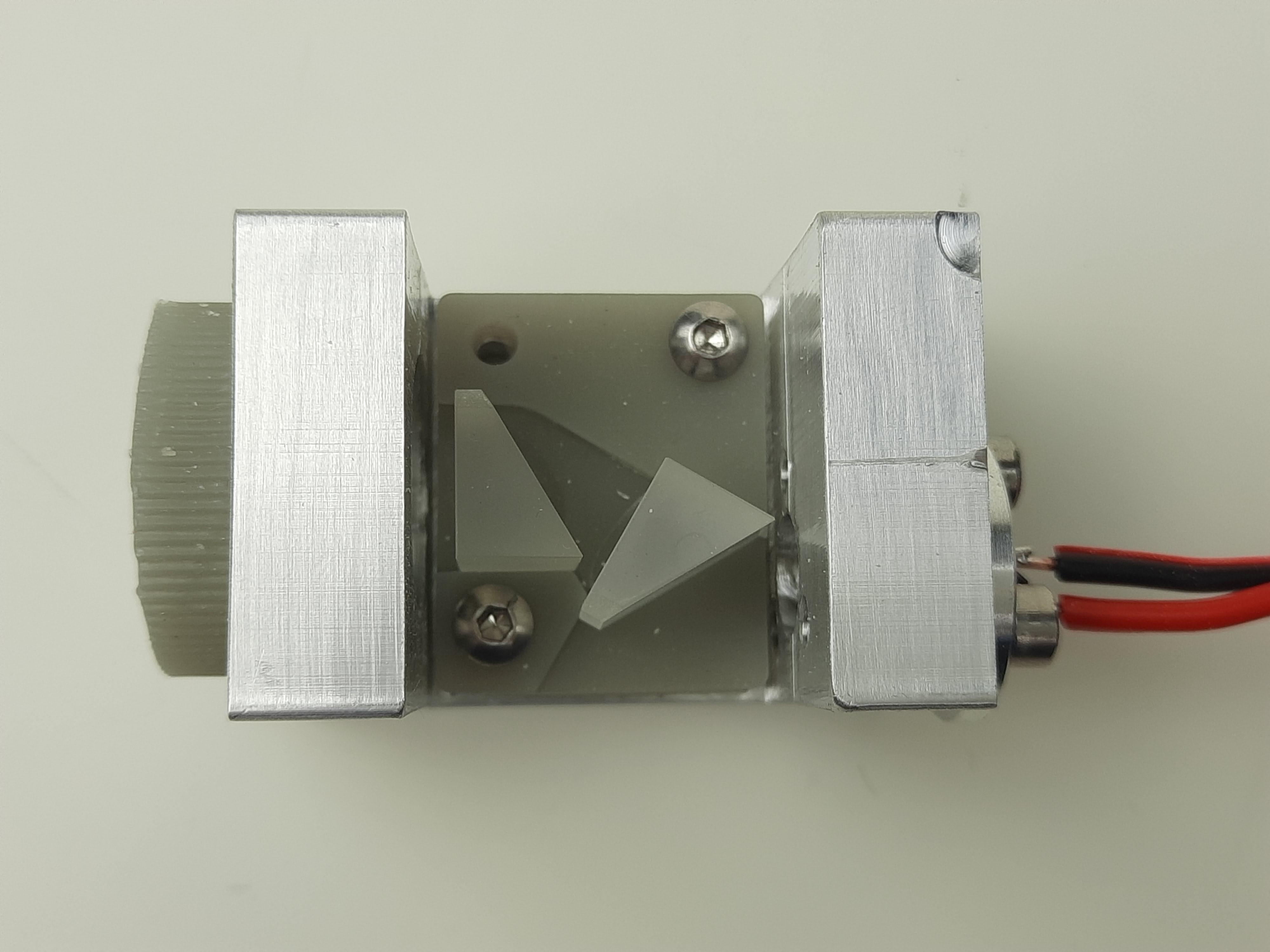
The housing was milled from 30x30mm aluminum bar stock. It has enough mass to work as a heat sink for short laser sessions, but can be bolted to a bigger heat sink for continuous use.
The laser diode is a NUBM08 which is available for a low price and has 4 to 6W output power, depending on how hard one wants to push it. Additionally, it comes with an already installed collimating lens, saving further costs.
In this version, the first prism is rotated ~30° towards the incoming beam and the second prism is nearly orthogonal to the outgoing beam, resulting in a 3x magnification of the laser beam. It’s fairly easy to calculate the exact rotation of each prism using the law of refraction. An anti-reflection (AR) coating is very important and even with one, the power losses due to reflection are around 10%.
The focusing lens is a simple double convex lens with an appropriate AR coating. Different lenses with different focal lengths can be mounted. Shorter focal lengths result in a smaller focus spot, bigger focal lengths in a larger but also more consistent focus spot for cutting thick material.
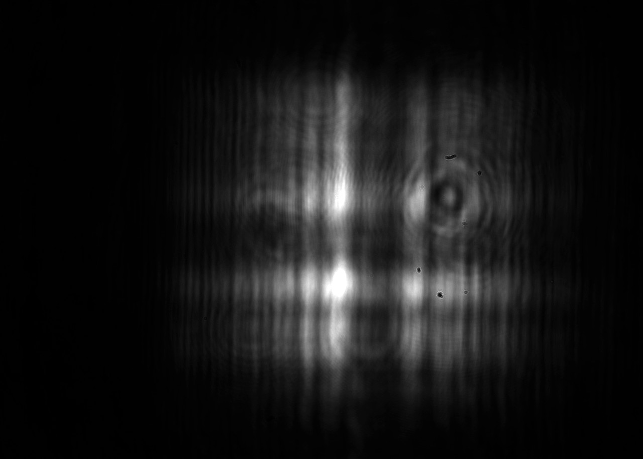
So the most important question: What is the effect of the beam correction? To answer this I built a small test setup which includes a microscope objective and a camera to record images of the laser spot shape.
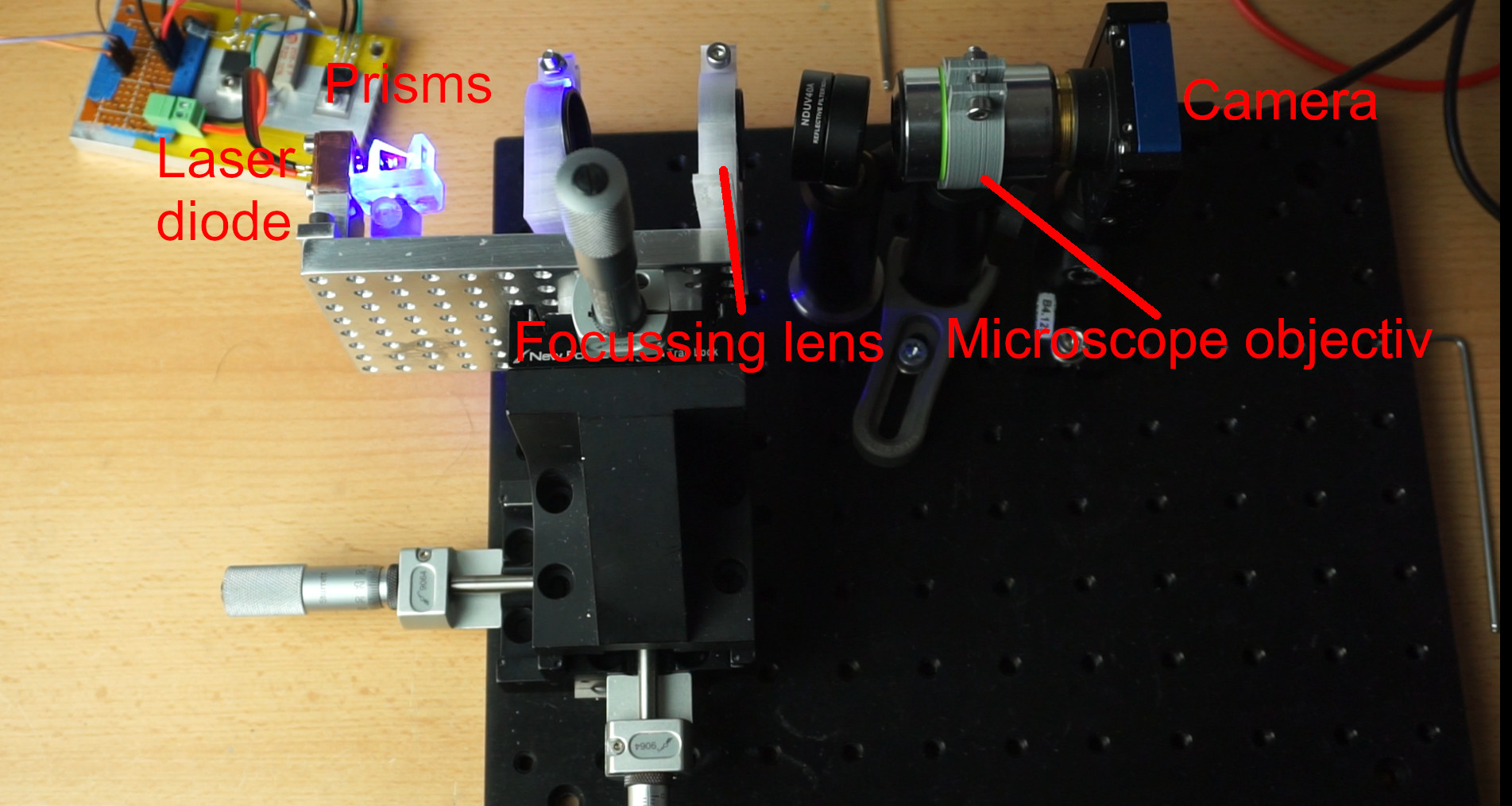
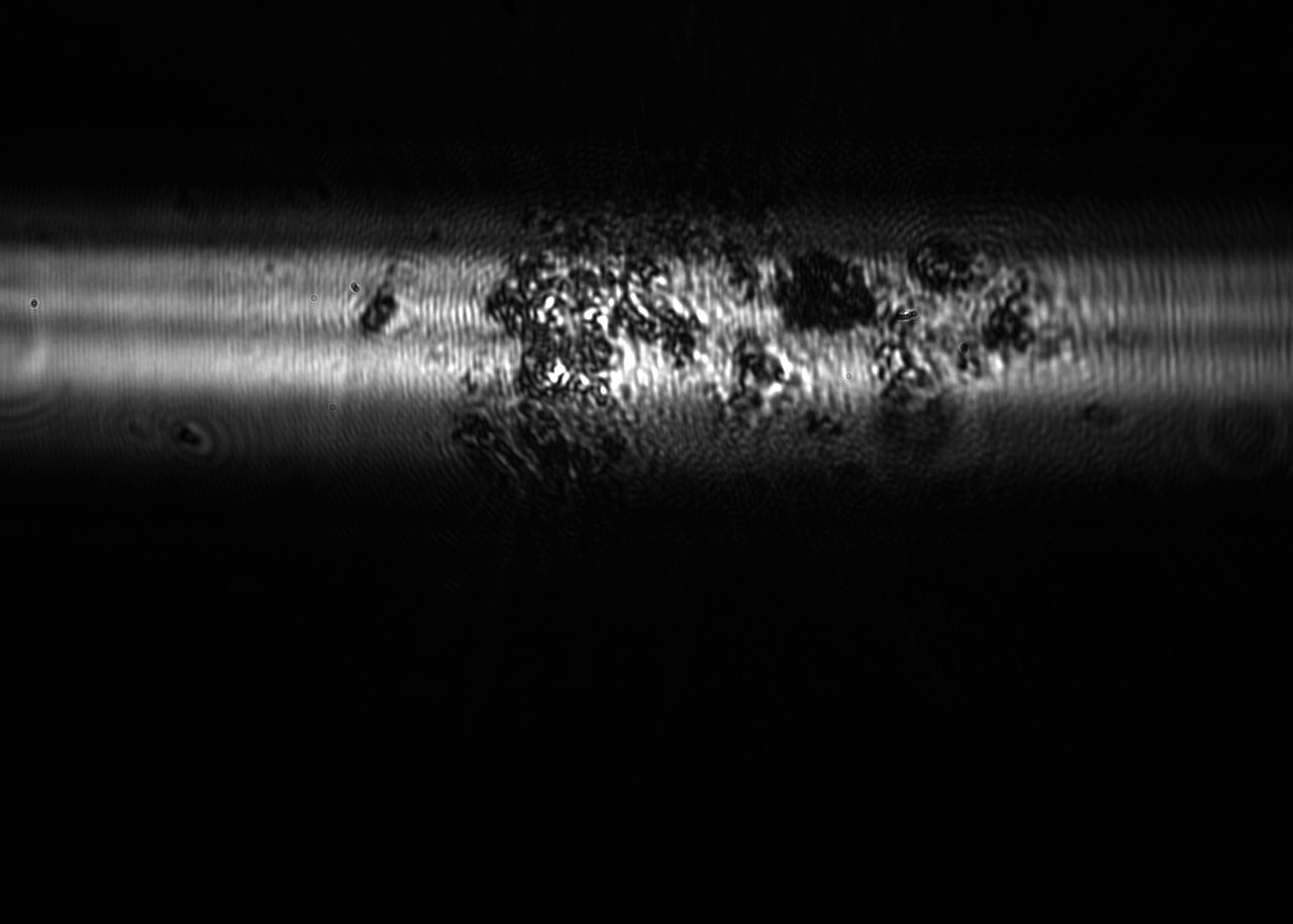
The image above shows the test setup with the first prototype (not the laser design shown above). The laser itself is mounted onto a translation stage which imitates the z-axis of a CNC and thus simulates the focusing process one has to do with the machine: When moving the laser back and forth, one can record 3 important focus spot shapes: The first, the optimal and the second focus spot. The reason there are two “main” focus spots is due to an optical aberration called astigmatism. What this means in practice is that one wants to do cutting and engraving using the optimal focus spot, otherwise engraved lines may have different thicknesses depending on their orientation and points would become rectangles.
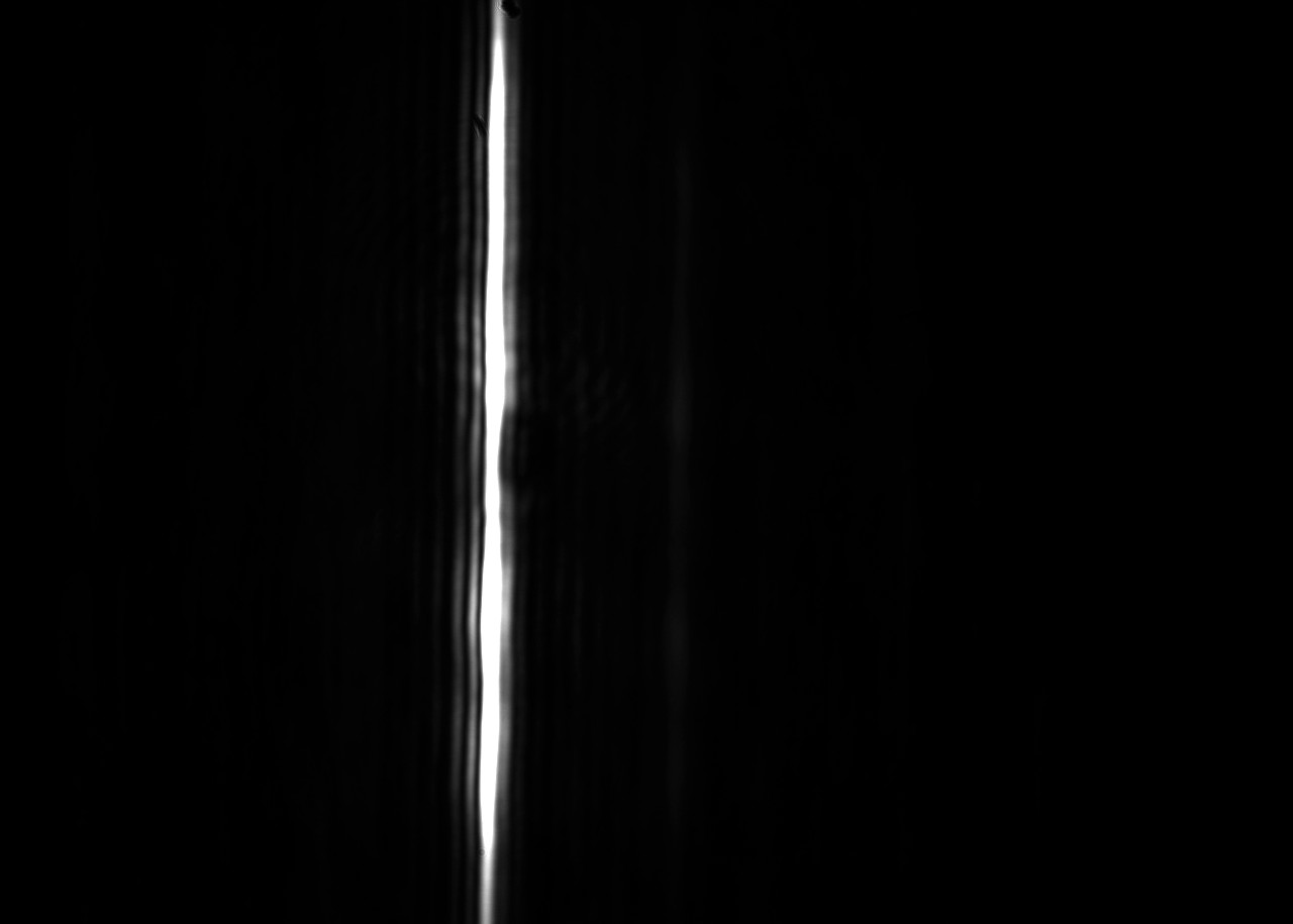
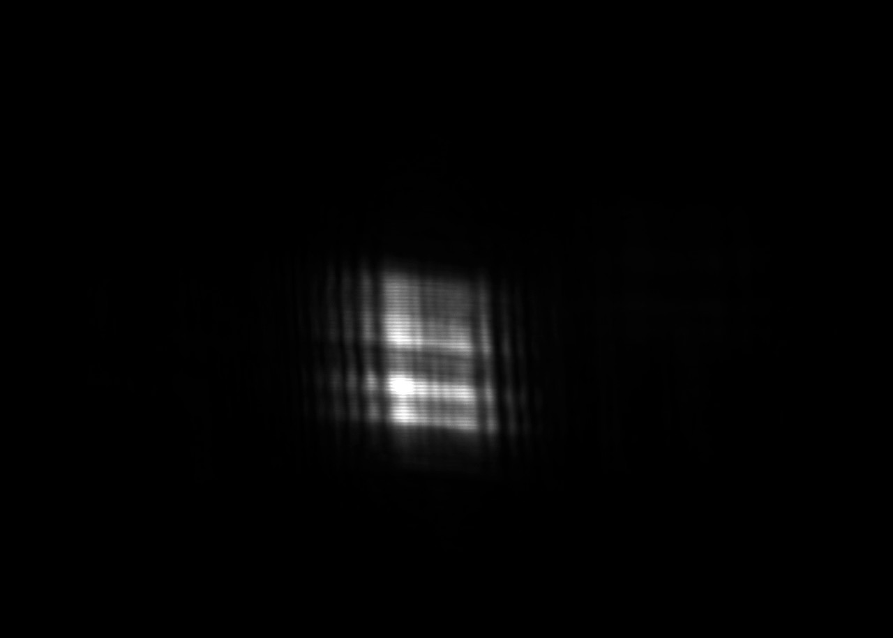
Here are the first, optimal and second focus spots without the prism pair:
Here are the first, optimal and second focus spots with the prism pair:
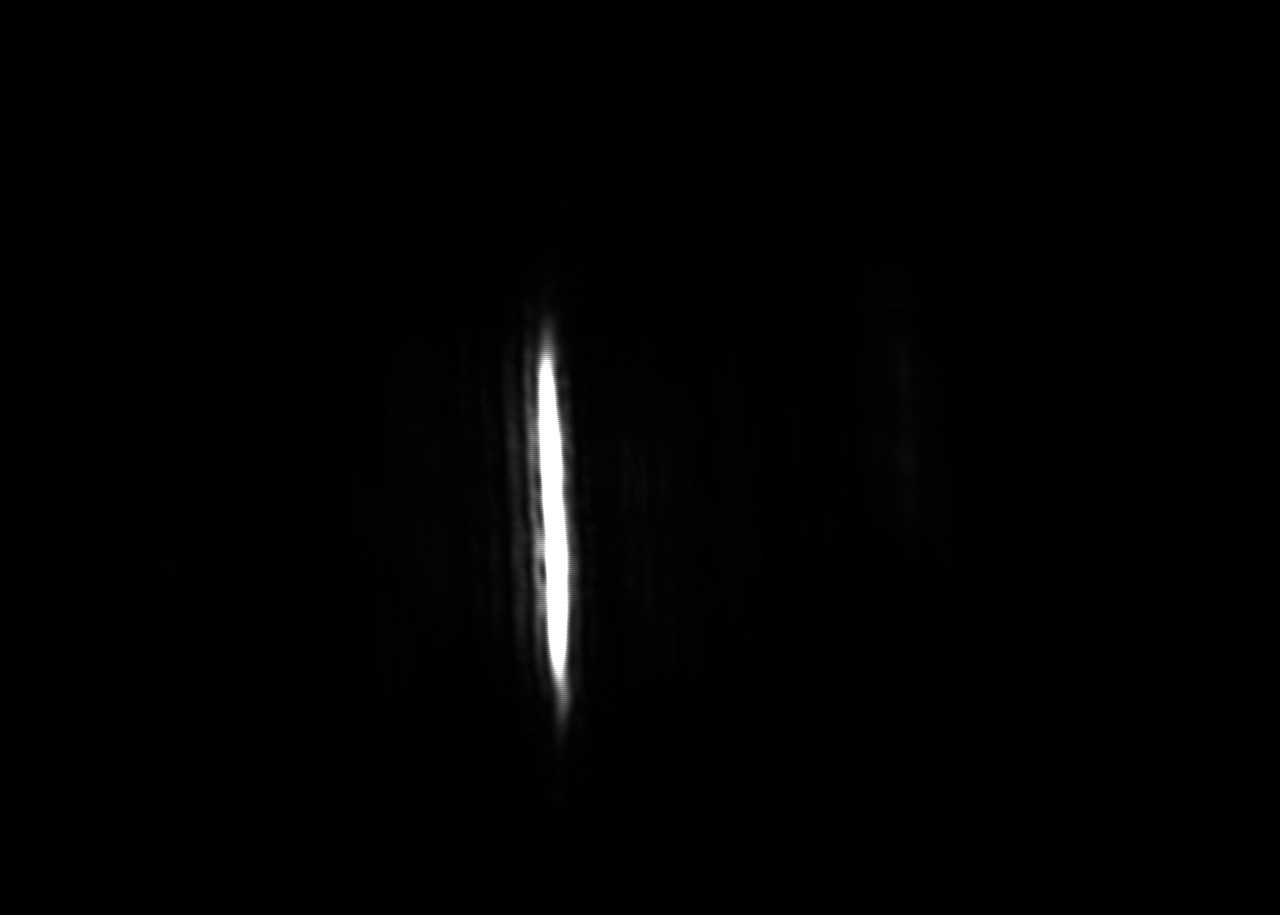
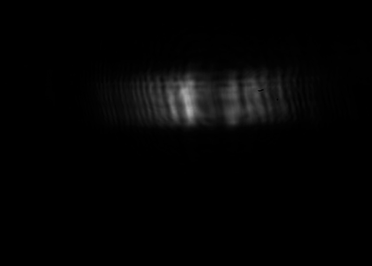
As you can see, the first and the second focus spots become less extreme and the optimal focus spot becomes ~1/4 the size by the addition of the prism pair. This allows for finer engraving, but also increases the energy density by a factor of ~4 (minus the 10% loss due to reflection). I will test if this is enough for stainless steel in the future, but first I wanted to do a quick test on the MPCNC.
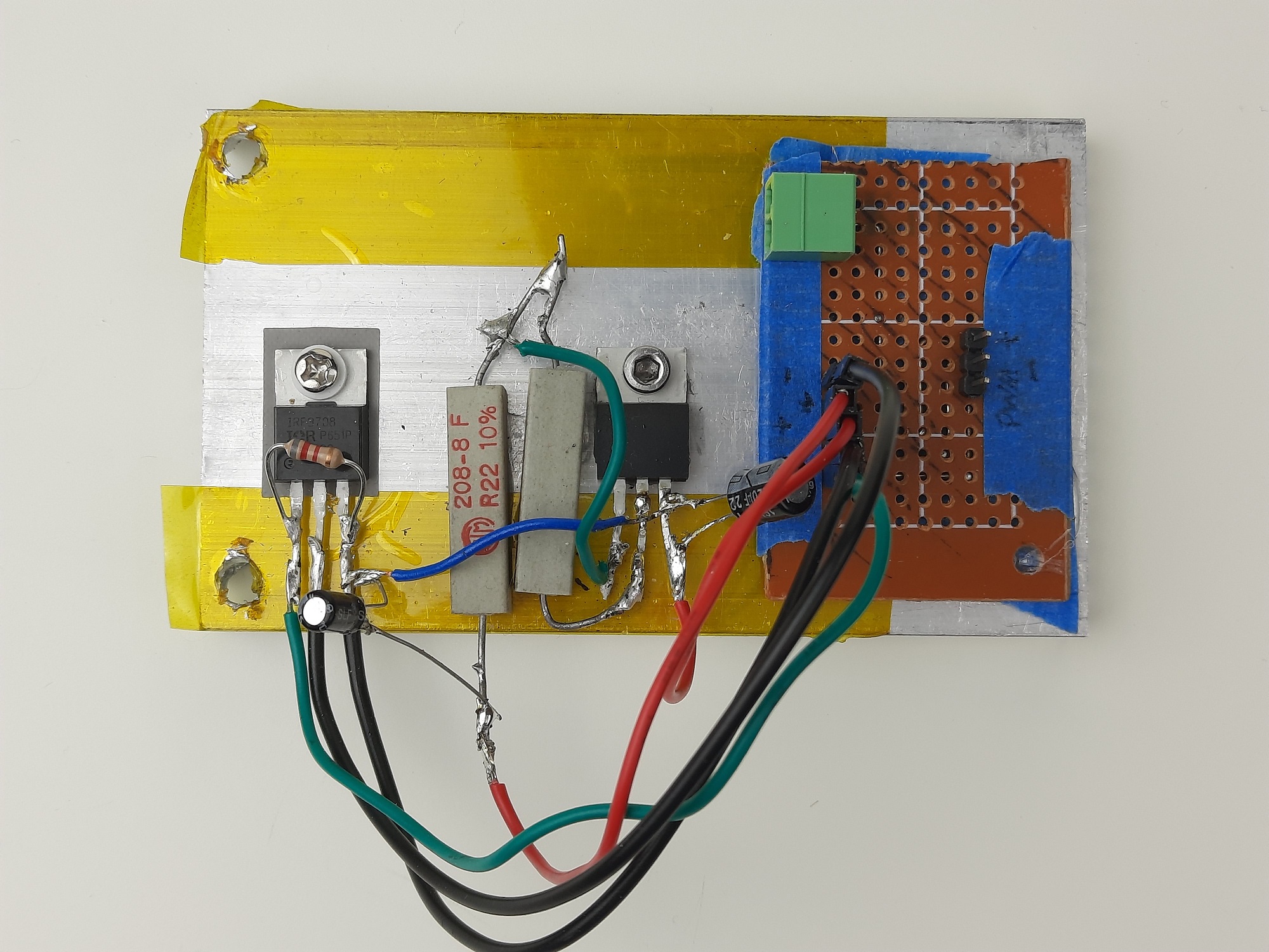
The laser driver was build in a hurry so it’s definitely not a beauty. But it works and should be good enough for a test run. A LM338 is used as a constant current source and a Mosfet for PWM control. The gate of the Mosfet is controlled via a pin on the RAMPS/Arduino controller.
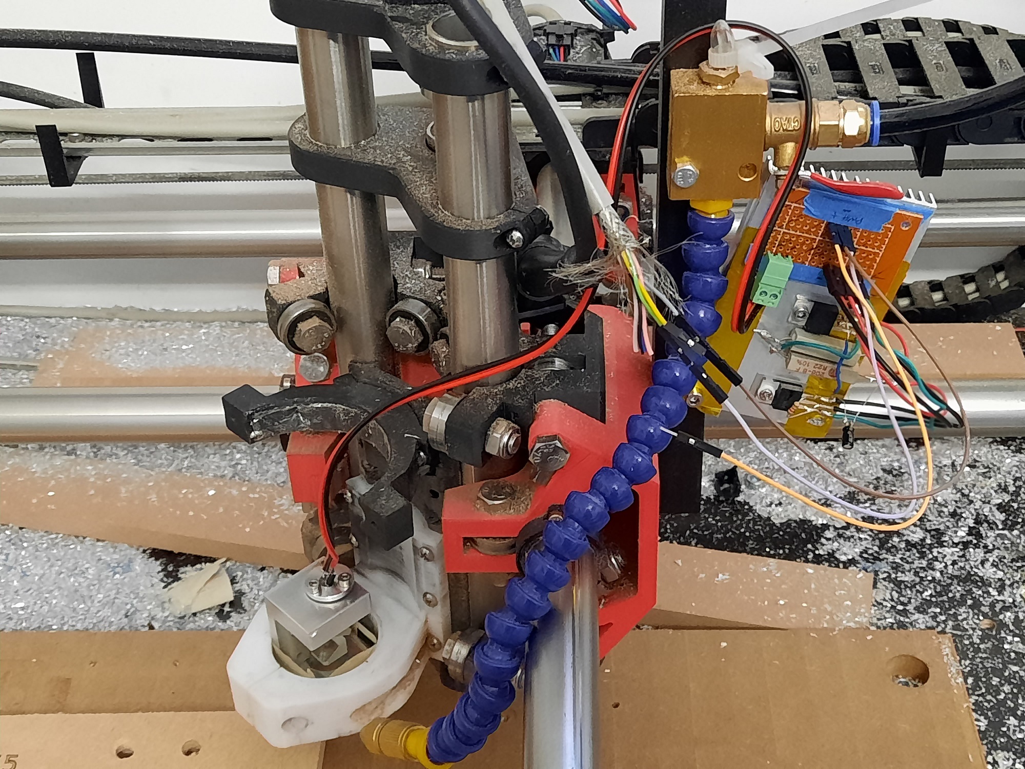
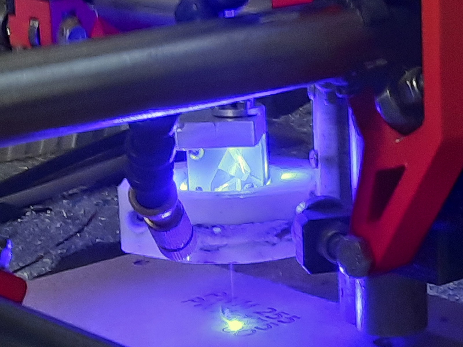
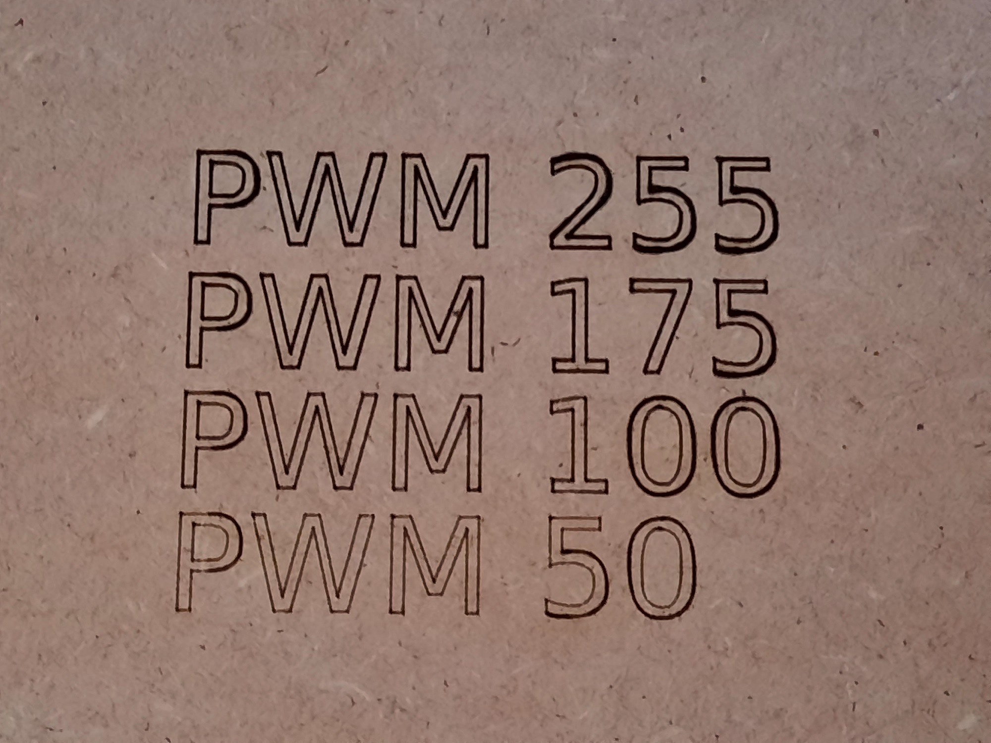
The fact that the beam is partially reflected from the prisms into the room is a safety issue I have to address before any extended testing. But so far the laser works well and the PWM control does its job. However, there seems to be a problem with curved lines, probably due to some Gcode problems.
As a next step I will add the necessary protection features, design a proper laser driver and then run a full test with different materials. As soon as I am happy with the design, I will publish all the files. But I still have lenses and prisms left, so if anybody wants to do some experiments on their own, send me a message.