Having a hole in the front that support a 3D printed part to hold the screen will make upgrades or changes to the screen a lot easier in the future. Good idea.
Putting it out in front so you can get to the jacks is another great idea. But with a mount, you have either option.
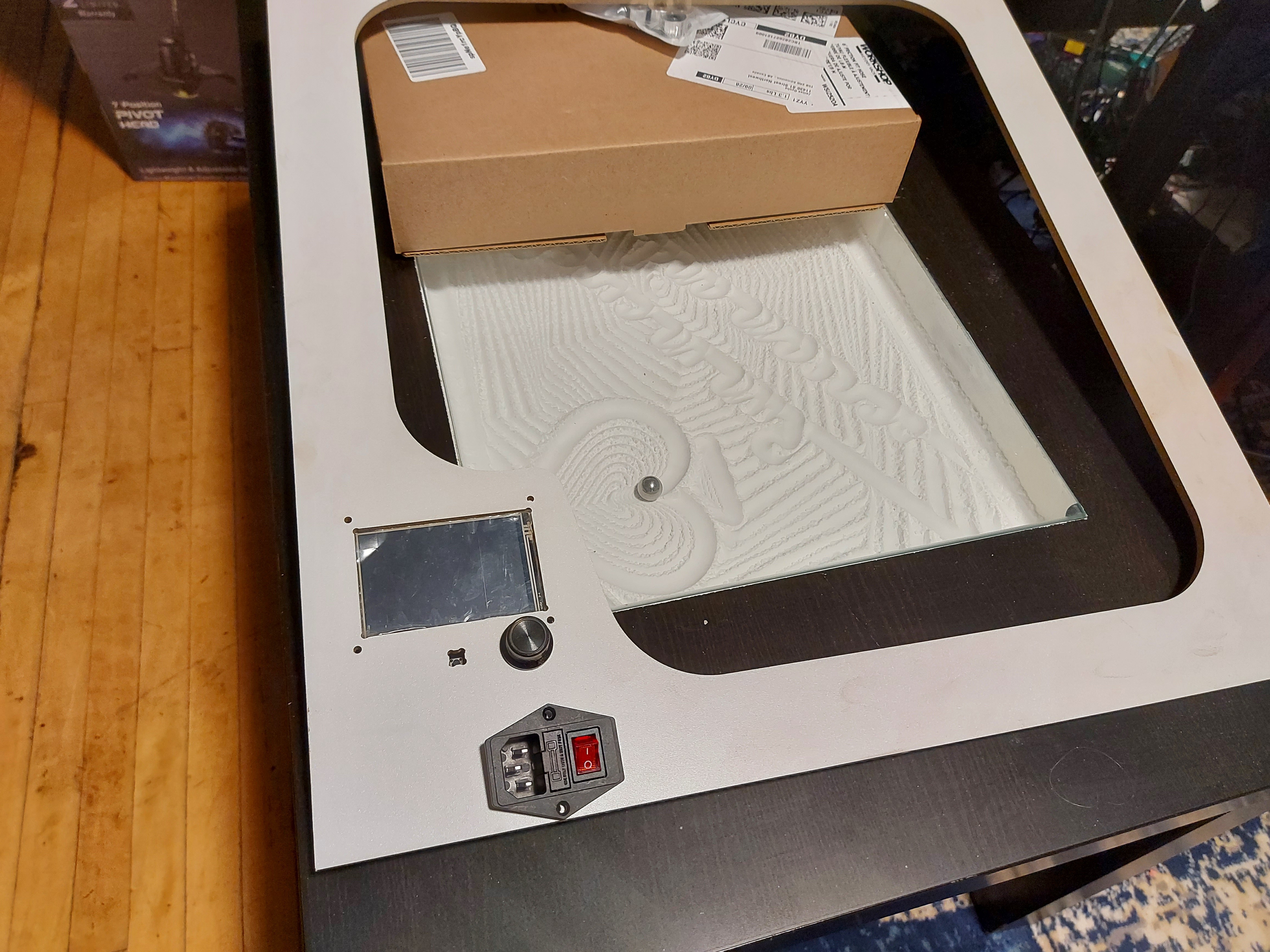
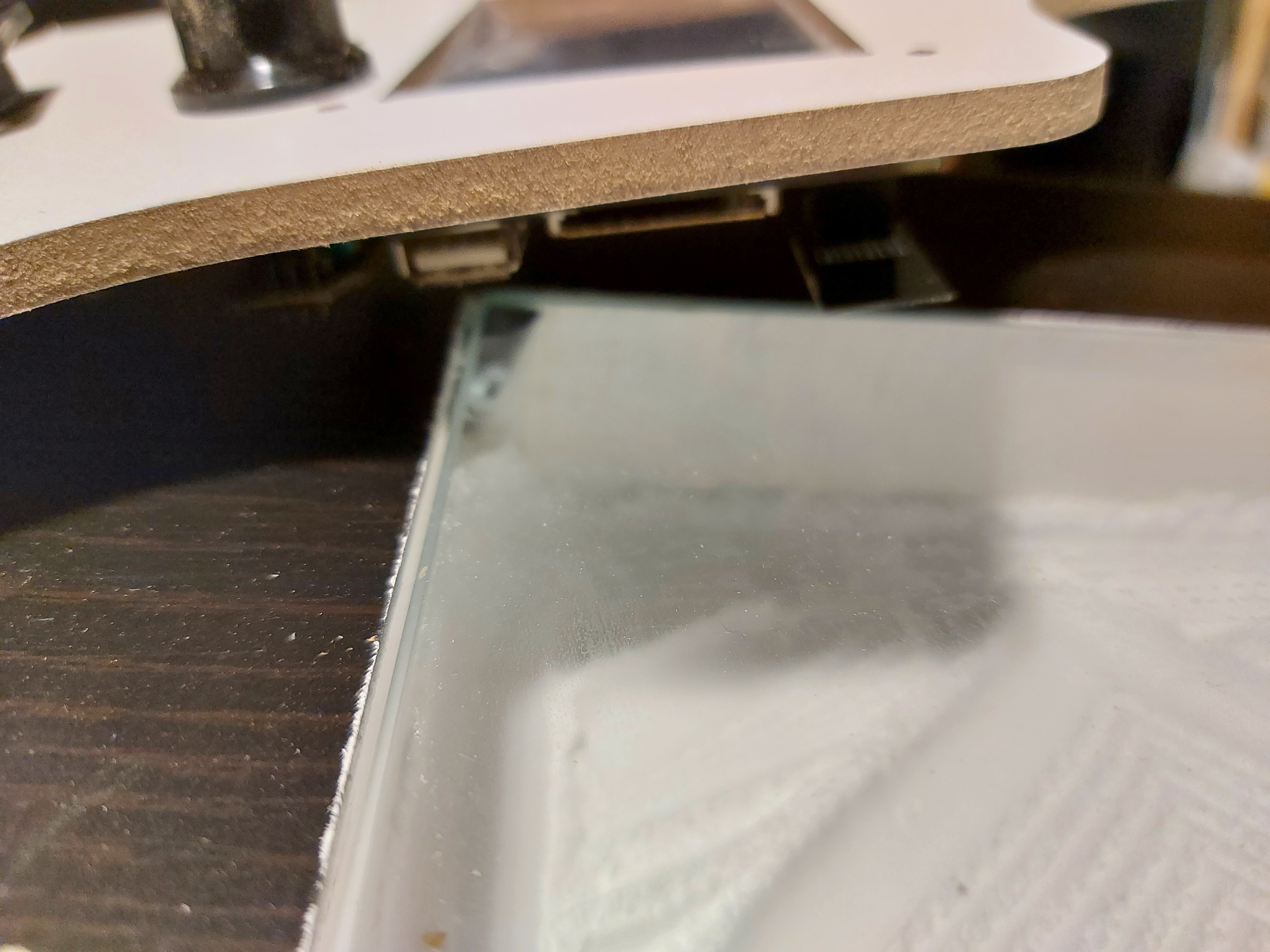
That is the foam test cut, to make sure it’ll fit. The actual panel will allow for reaching the USB port and SD card slot. That said, if I can transfer wireless, it’s almost 100% that I’ll do it that way. Once I had the wireless.set up on the Primo and my current printer, I never popped the SD card out.of them again, I do all the file management over wifi.
I’m kind of treating the whole front panel as a mount. It could be 3D printed, but I can mill a whole new part, and mount it in place in less time (now) than I could print it.
I had intended to have a mount for the V1 printed case, but the case doesn’t have the opening for the wireless antenna. It can go on the LCD or main board, so I could just use the main board mount, but the LCD is where I tested it.
So this morning I called Canada Post about my CF tube, which had been “out for delivery” since Sep 15. I was told "The delivery agent said “No access to building”
Nice. So they didn’t call (They have my phone number and email address on the customs declaration) didn’t notify me and the tracking information still said “out for delivery” (With a “delayed” notice) so no way to know before calling.
I remained polite, but basically said that the person was an idiot. I live in a single dwelling so there was no need for “access to building” unless they tried the wrong address entirely. I verified the address it was being sent to… And lo and behold, it was in my mail box 3 hours later. So now I have it.
It’s 500mm in length, so I need to cut it down. (460.2mm if memory serves is 120mm longer than the model originally had for a 200mm build plate.)
Did I say that this printer is going to be behemoth? 100mm extra doesn’t sound like much, but it really kind of is. There have been times where the “standard” 200mm build plate has been a restricting factor when I want to 3D print stuff, so I thought that being able to go bigger to 300mm would be really nice, so that’s what I wanted to try with this. If it were an option, I’d have liked to be able to get just a little over the 12" mark, so I’m about 5mm short. (Well, the plate itself is 310mm, so I might actually be able to do 304.8mm if I give a little credit for the heat spreader, and am very careful with centering my prints.)
So now I’m waiting for my longer 3mm screws, then it’s time to start mucking about with parts, and seeing if I can determine a reasonable order of assembly operations. (I’m usually pretty good with this, but I may have a few questions for @vicious1 once I get my parts cut.
Yeah it will be big…but compared to a comparable bed slinger it is actually smaller.
Order of operations is very forgiving on this one. The only gotcha is the CF tube and the trucks, You can do it is several ways but the key is to screw the 3 screws to the bearing block and leave the 4th a bit loose to let you tension it (and twist the rail if needed). The proper way is probably assembled it out of the machine and then bolt the whole thing in by the rails, but I have done it several ways. Heck if you didn’t use the 4th screw it would be simple. I don’t think it is needed.
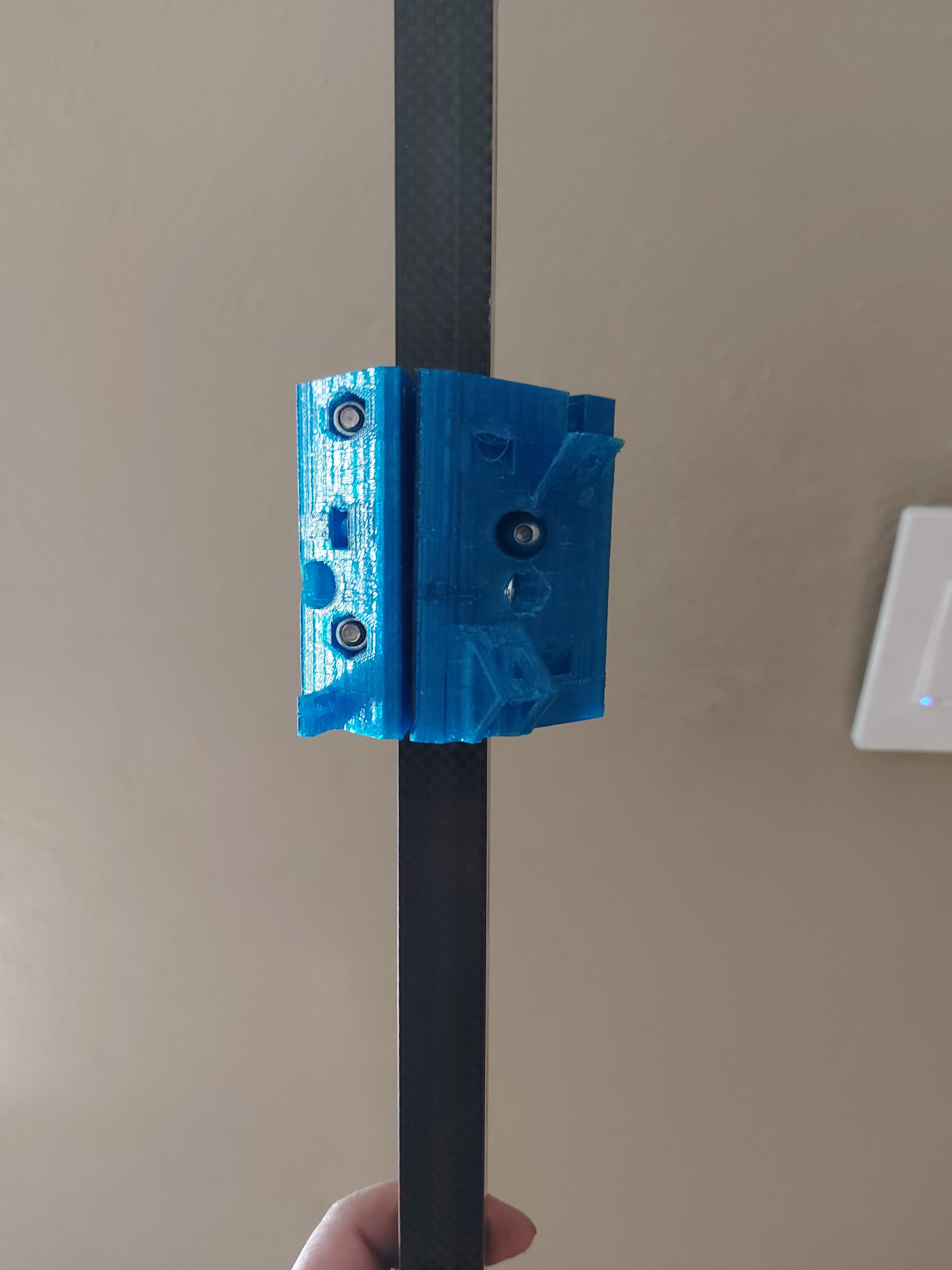
Test fit the hub. I spread the gap as wide as I could after threading in the wheel, and good thing, it’s quite tight that way. I don’t want to put any pressure on it. Standing the rail on end, the hub won’t roll down, though with a bit of finger pressure it rolls smoothly.
Yeah, the footprint isn’t much different from my current bed flinger, but it’s quite a bit taller. (Like, say 4" of build height)
Nice use of materials and guaranteed opacity. Something that you won’t mind tossing if it’s cut wrong, all good! I haven’t put them together, but the concept works for me.
I’m probably going to want to put together a “stock” size of this printer at some point. One more kid who wants one.
Option 1. Make near identical MP3DPv2 to prevent sibling rivalry from breaking to near war.
Option 2. Make v3, and watch the fireworks.
Option 3. Make 2 v3s and youngest gets an upgrade.
Well, let’s face it. Option 2.5. Make v3 and accept that I’ll need another identical one soon after.
I only tightened the 30mm screws so that the threads fully engaged the nut. I tried prying the openings and a couple of them had the screw threads pop. It’s a little looser now, but still won’t fall of by itself.
I think it’s OK though, it takes very little force to move, and the movement is smooth. I figure that it will “wear in” after a little use, and then need some tightening after. I think it’s within the range of my printer accuracy. Mine really doesn’t like overhangs, even 45° is sometimes more than it will handle gracefully.
On the hub, there are 3 nut traps that have the flat surfaces horizontal. My printer had some sagging bridging this. I fixed it applying heat to a regular 5mm nut and pressing I into the opening with the sag upside down, then pulling the nut out. It seems an unusual design choice for your parts (you seem to normally make sure that the points for the nut traps is vertical.) I figure that the internal tolerances are pretty tight for this part. I’ve never rigged up a working part fan, so bridging has always been less than good. It’s one of those things I meant to get to. (I have the wiring in place, just no fan.)
Not a big deal, but if you look, for the 6 axle screws, 3 of them have the flats vertical, and 3 have them horizontal. Pretty sure there’s only one reasonable orientation to print that piece.
The span for an 8mm nut isn’t out of the question, but my printer is weak thst way. One of the things the new one should remedy, or at least give me some time to address. (I meant to do so with the V2, but that didn’t end up happening.)
I also need to address print quality issues, mine has developed “X wobble” from the leadscrew drive. You can see it in the hub print. It’s small but visible.
Yeah, not happening. Ages 17 (on the spectrum) and 20 and wants to print stuff that will take 16+ hours. Neither one shares well, and I can only imagine what the arguments would be like if one of them uses up a spool loaded in the printer the other wanted to use. NOPE. Gonna be easier to have more printers.
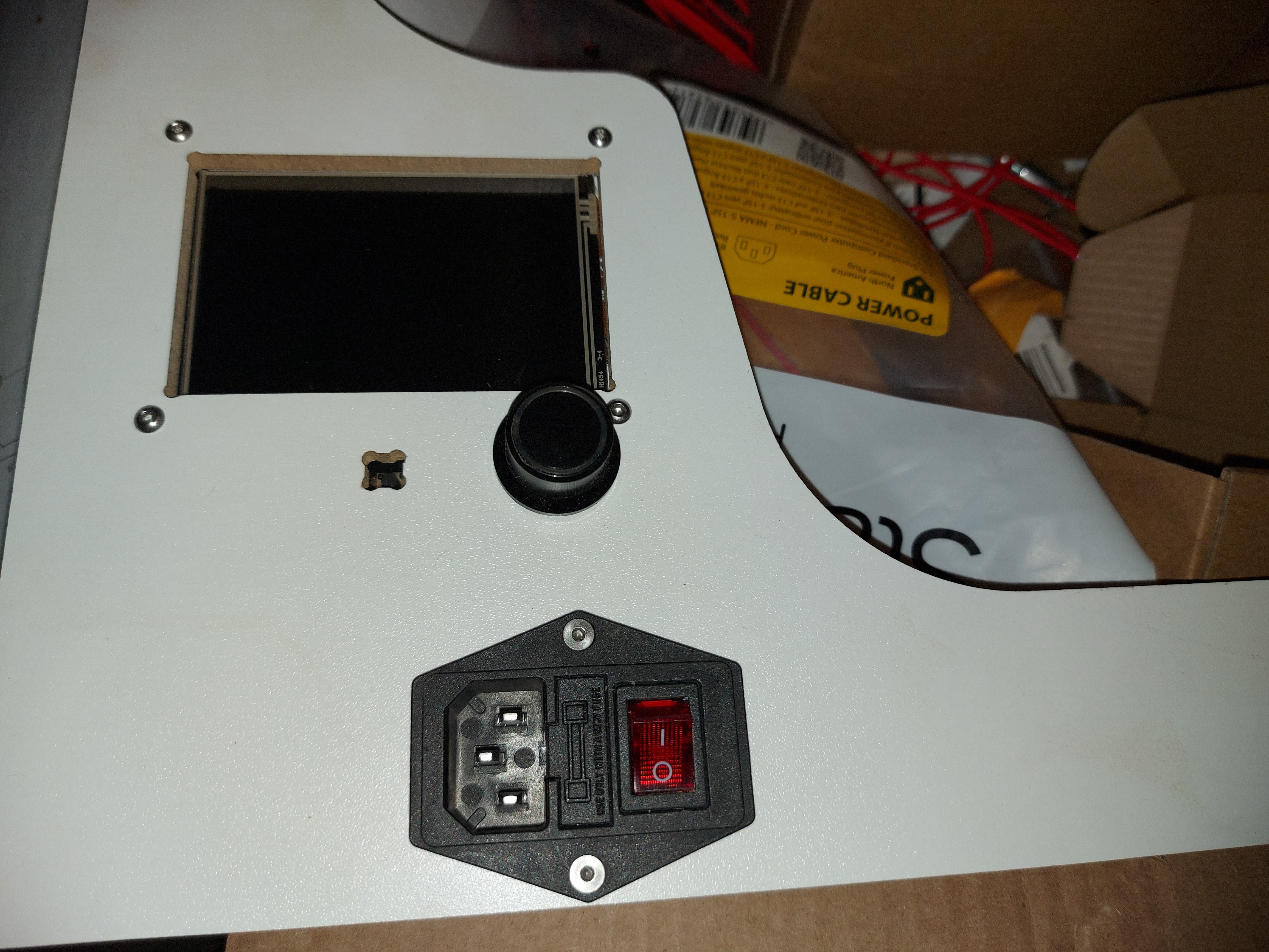
Properly mounted and screwed in. I used 6mm standoffs for the LCD which places it flush with the rear surface. This is barely short enough to allow the LCD rotary encoder knob to be pushed with the panel, but should allow the LEDs to light it if I want to use Marlin mode.
I will paint this panel at some point, but not too concerned about it yet. I’ll wait for the rest of it to come together.
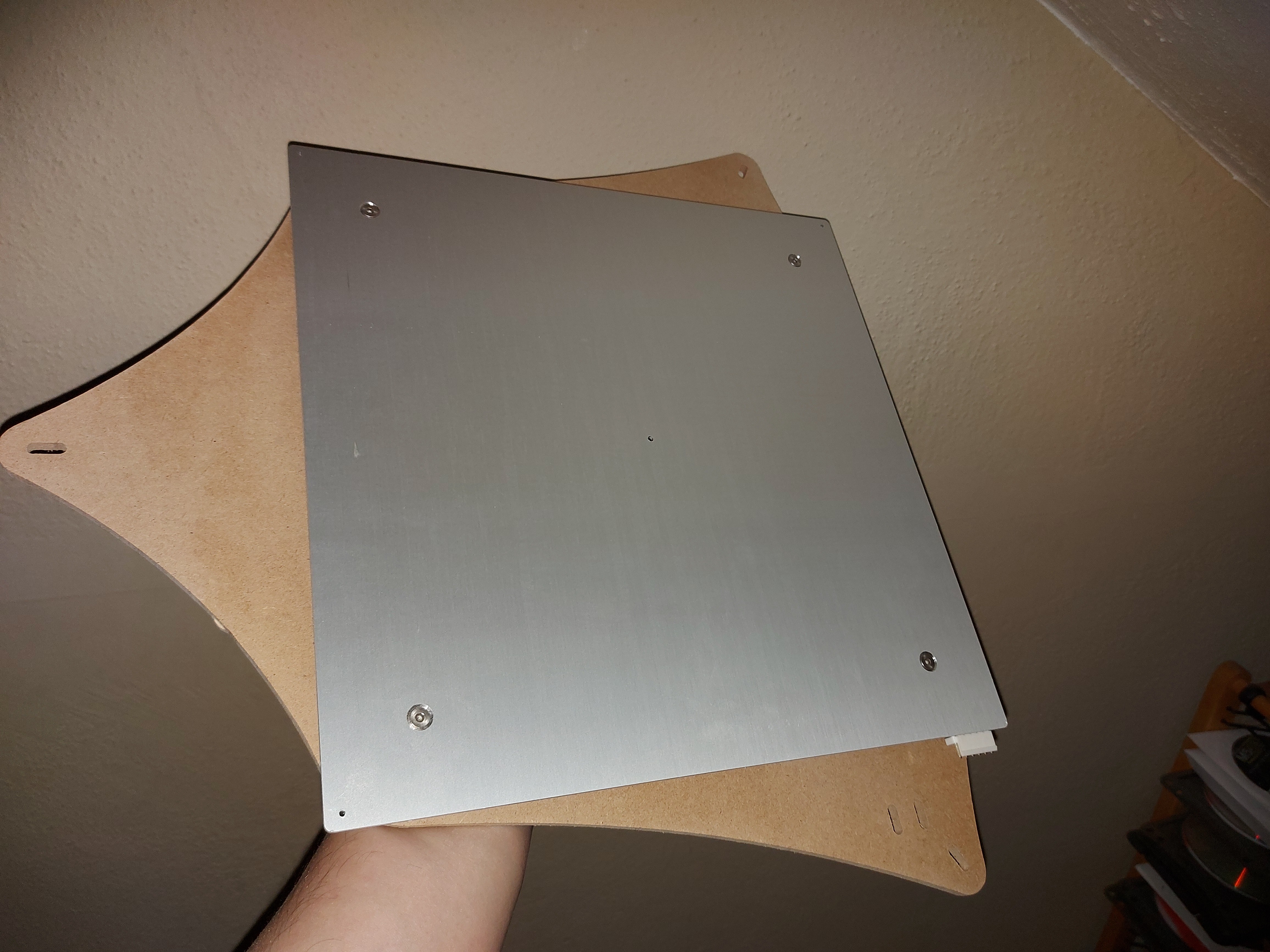
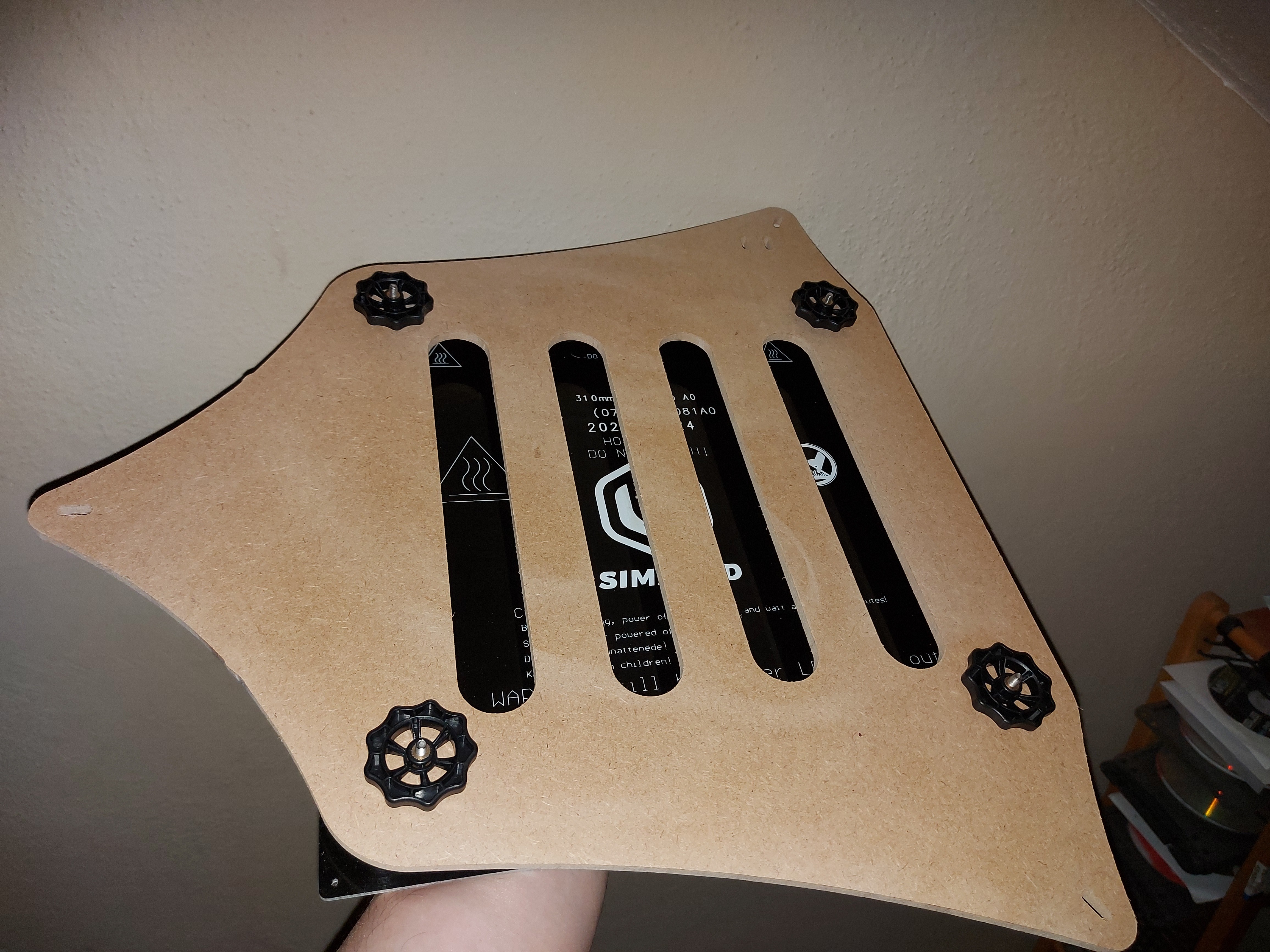
Bed support done. I was going to use the same melamine paneling I used for the front, but decided on regular 1/4" MDF instead. It won’t matter once I paint it, really. Either paint or melamine will offer some resistance to warping from proximity to the heated build platform. I do plan to insulate the bottom for that, too.
Well, a lot of back and forth on this, because I’m using this as a build to debug the LR2, and I apparently have a lot of bugs in the LR2 to work out.
I think at this point, I have all of the parts. I need either another sheet of 12mm MDF, or another sheet of 12mm plywood. I think the plywood would be nicer, but the dimensional stability of MDF… And the weight. Ugh, this is going to be HEAVY in MDF.
Maybe some openings in the sides would be a good idea. At least handles or something to help carry it for the (hopefully very few) times I might need to move it. It might reduce the heat insulation capabilities, but certainly not as much as an open extrusion frame.
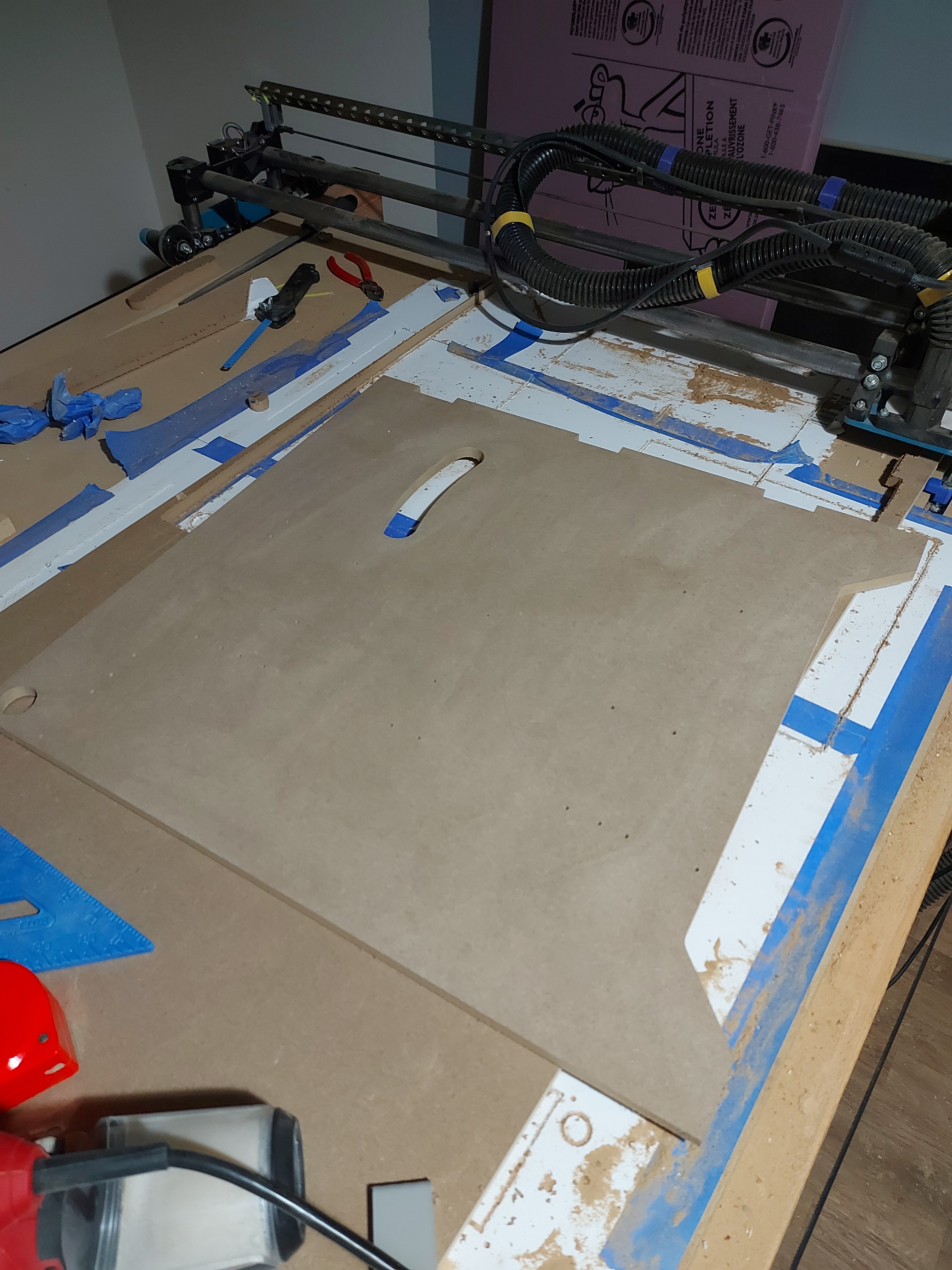
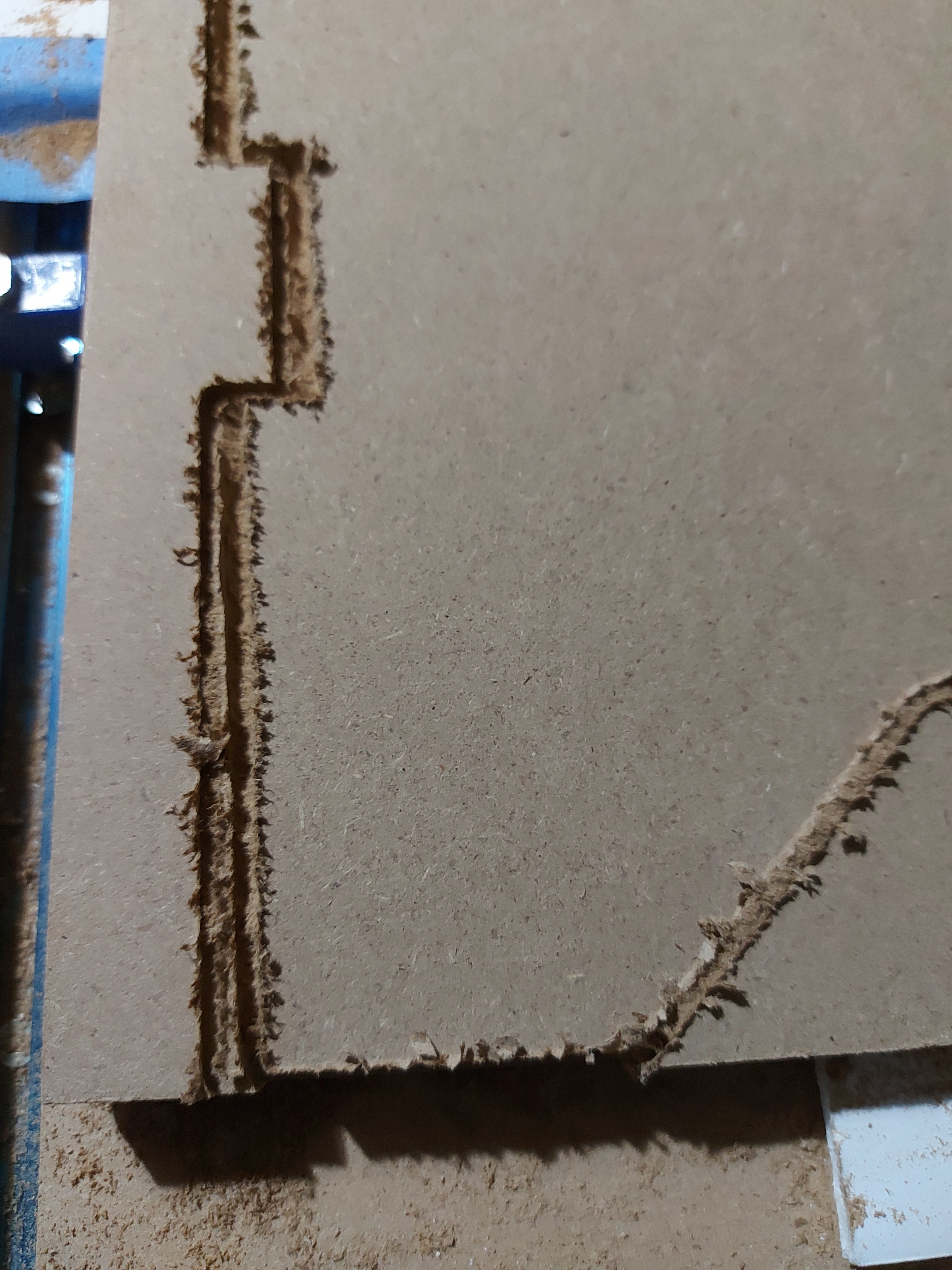
Made another piece of junk. The diagonals are out by over 1cm. The mount holes for stuff are as close to dead square to each other as I can measure, but something slipped on the first pass cutting the outline, and then it was all garbage.
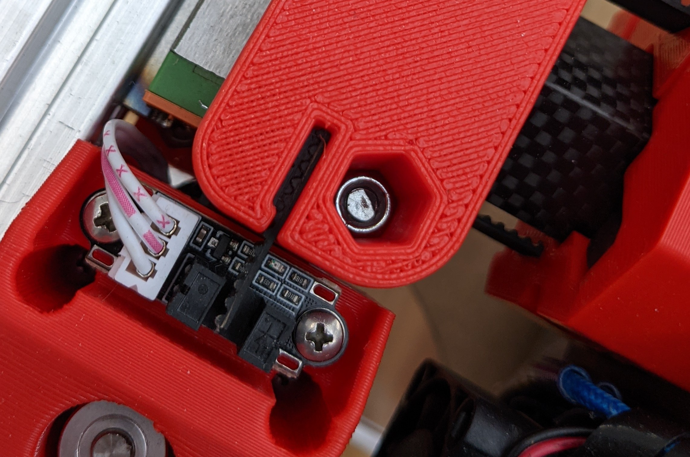
I think it was the X axis that slipped. I’ve been having trouble with the one motor plug, but then it should have remained square, so it’s possible that the Y2 motor slipped, which skewed the cut.
Looks like I need to attend to the wiring, I have JST XC connectors for thr SKR, have just been using the Dupont connectors until I got to cleaning up the wiring. Looks like I’ll have to do that.
I’m a bit worried. I got some skipping in X before, and bumped up the current for the X motor to 1100mA, which seemed to deal with it. Maybe I need a bit more, though I don’t think that I should. Maybe my X bearings are a little too tight? It still seems to slide smoothly though.
I’m about this close to just cutting on the Primo. Just innate stubbornness keeping me in this track, but frustrating when I have a solution I know works.
If the drivers get too hot, they will either turn off, or they will reduce the current themselves. Counterintuitively, more current can cause them to slip too much.
Also, the motors can get very hot. They will make the motor mounts soft. The rule of thumb is 50C motors seems to be a good upper limit.
Another odd one that can pop up is static from the vacuum, I think that usually resets the control board, though.
Any chance your rapids are too fast (on the LR I have my rapids pretty slow 20-25 I think), or cutting a little too heavy or dull bit? The pealing on your cut is not looking like mine do. MDF is the hardest thing to cut other than metal ( I would be at 1/8" single flute, ~4mm DOC, 10mm/s). I baby the LR compared to the MPCNC (1/4" 12mm DOC 25mm/s).