I haven’t tried it but It is a paid product. Teaching Tech has a wonderfully complete tuning program for free that I have used several times.
2 Likes
Yes I have went through the Teaching Tech site too, super well designed for step by step tuning. Michael is great and a huge resource for all of us.
Just was wondering about the other tuning options out there! Seems like 3doptimizer might have several speed type tests that could be useful that looked a little different than TT’s stuff.
From @gpagnozzi s build thread…
I figured that I could weigh in. I figured probably better in my own thread though.
Given that engineering choices are all about trade-offs, I do see some patterns there. Many of these patterns I’ve kind of broken with my build choices, but that’s of course completely on me. As compared to other build styles, you’re far more likely to choose a 2 part structure to hold pulleys and idlers. This is quite evident in the LowRider, as well as the ZenXY builds (both of them) and what I saw for the older MPCNC, though not the Primo. I see this as a decision that is generally to eliminate a need for 3D printed support pieces, while providing double ended support for axles. On the whole, given that my printer has always been weak at bridging, and that I despise supports (and trying to separate them from the printed pieces) this appeals to me.
You also will sometimes do things that it takes me a while to recognize that are to decrease unique parts, both printed and otherwise. I get this from a kit point of view, it makes so much more sense to have all of the xxx sized bolts the same length where possible, and eliminates packing errors. This is the design decision that I’m most likely to change up with my builds, by changing materials, or sizes.
And of course, you make some design decisions based on hardware that’s easy for you to source, or that you will have on hand from other projects. Most of it is also pretty easy for me to source as well, with some funky stuff around Metric/Imperial that are regional issues.
Rather than patterns, I see evolutions in your designs. Some things, like the bridging tricks in the screw holes have been around for a while, and since they’re good ideas, don’t change much anymore. Some things get simplified as unnecessary parts get removed. For example, the belt locks on the LowRider using zip ties and the little rounded inserts became the lock piece on the Primo, which became that folded lock in the ZenXY, and then became the clipped piece locks that you use here. Each one is a step towards a more simple, compact lock that still has adequate strength for the belt tension, but becomes a little smaller and more compact.
For the low unique printed part count, as it applies to this project in particular. The low model count is nice, and from the standpoint of making replacement parts, it’s pretty cool. Using the same motor mount 5 times in particular is great, and the repeated Z axis has some nice advantages.
The mirrored Y trucks took a bit of thinking on to make sure that I did things like put the rails on the correct level, and I did mess up my CAD a little there, because I spaced it for the motor sticking up to be on the lower level, though it’s the other way around. I guess I let that one variable slip, but since it also put my side plates at 600mm (So I could fit 2 on a 2’ by 4’ plywood sheet) it’s probably for the best that I didn’t make it that little bit taller.
Overall though I didn’t really see any real downsides to the repeated parts. There are some provisions (like for the X and Y belt chunks for the optical stops) that are underutilized, (My X stop belt chunk is held in with hot glue, because I didn’t put it in before assembly)
I still see your designs as being a cut above for ease of building, but then having built a few of your machines (All of the current ones, I believe), I can make some intuitive leaps in how things are likely to work, and that makes it easier and more straightforward.
3 Likes
Thank you for that!
The beauty of this for me is I am less worried about kitting it up and more concerned with the instructions. Not having to write M3x8, M3x10, M3x12, M5…ect. The win win is it works both ways.
The reason I did not do a lot of it initially is it is wasteful from a ultra efficient engineering perspective. Why carry the weight of larger screws and the larger parts to hold them and the longer print times that bring? Initially it sounded so very wasteful. Once I got a few years in, I realized the difference between a purely designing engineer to one that also sources, ships, writes instructions(occasionally (looking at you Zen2)), and answers tech support questions. Gone are the days of asking if you used a 1.5" bolt or a 1.75"…or 2". All this falls apart a huge scale, or an assembly line scenario. For the garage builder and self sourcer I think this is the right direction to evolve.
Can’t wait to make the next LR, that build took a wrong evolutionary turn and I regret a lot of those choices. IT functions great but is a hassle to build, source, kit, and troubleshoot. Luckily it has all gone pretty smooth, but subtleties in parts and hardware choices does not go over well for the DIYer.
3 Likes
Any updates? I was kinda waiting to see what you guys thought before the big release.
Other than that I’ve been using it pretty hard, nothing new, really. I’ve gone through a few spools of filament, but haven’t got much done on the printer itself.
I did burn out my first 5015 part cooling fan. Probably means the rest of that batch will be short lived as well, but I’ve got a dozen, so I’ll just have to make them easy to replace.
I was pushing speed last night, and had it cranked up to 140% just to see, and it printed perfectly, or at least within reason. The slicer was set for perimeters at 65mm/s and infill at 80. I could easily hear differences as I increased speed, so pretty sure that I can print at least that fast. (My configuration is set to have a max speed of 125mm/s)
I did run some speed tests, calibration prints and so forth, but mostly, I’ve beenfiddling with no solid conclusions to post up.
As to what I think…
I think that I spent pretty close to what a mid-level kit would have cost. Something like printers that I’ve had before, and I’m getting print quality and speed that is vastly superior.
I generally keep spare parts in case something breaks, and the low number of printed parts means fewer spare parts to keep.
Now… I’ve got to build 2 more for the kids…
4 Likes
Awesome!
I haven’t play much with the printer, I’ve been out of the country for over a week and I still need to finish cable management.
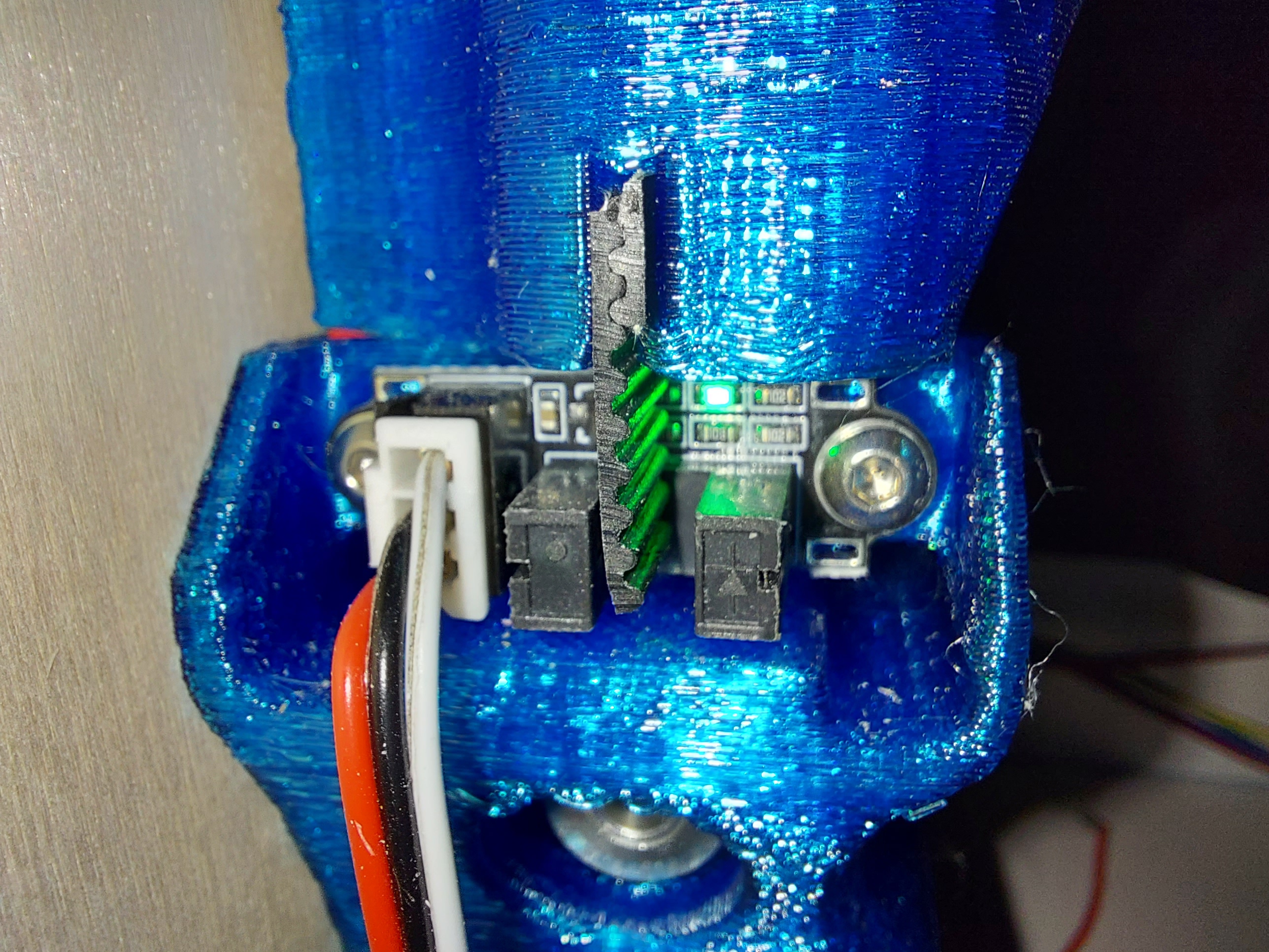
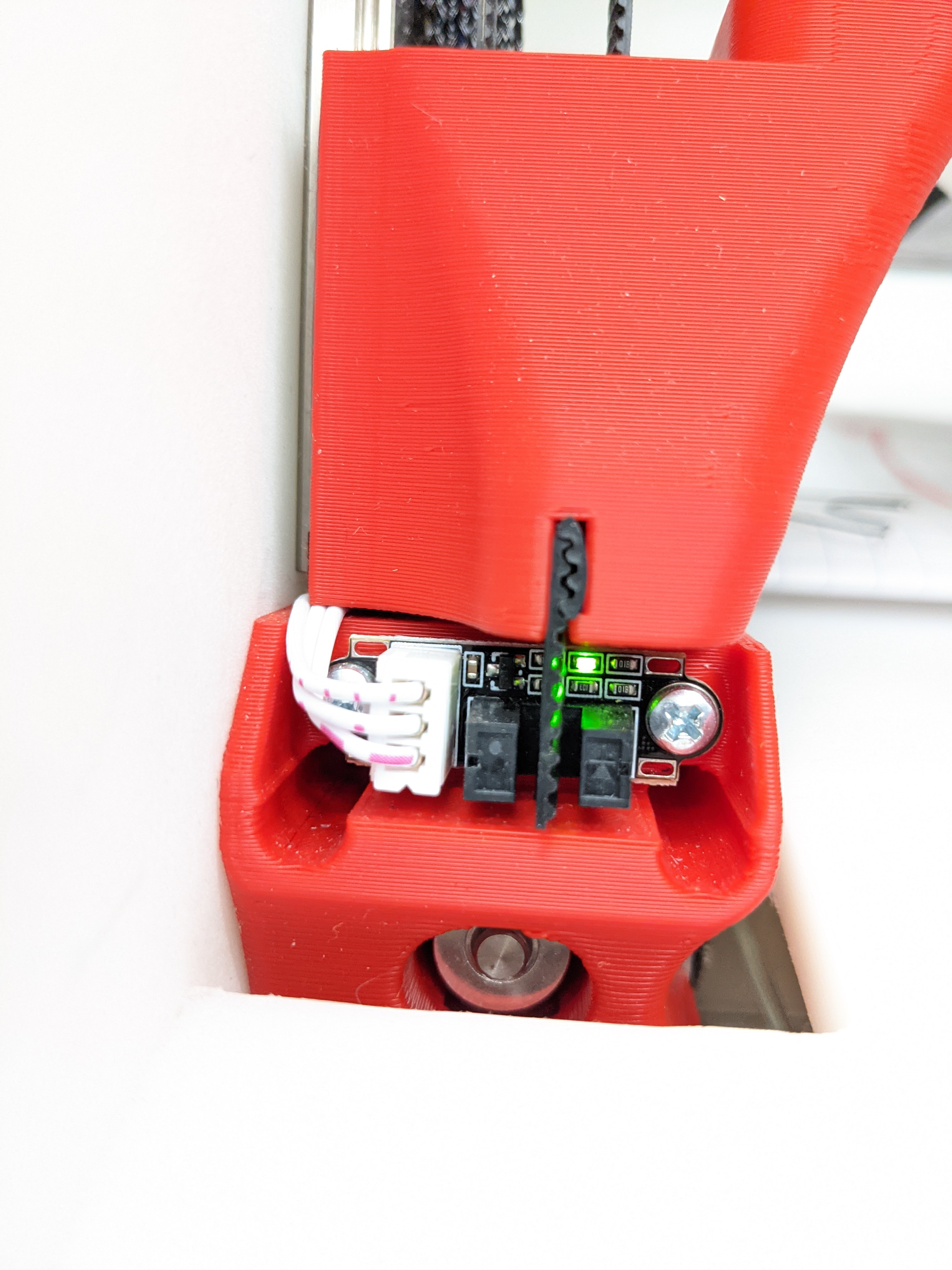
The only thing that I would change is on the Z belt slider, the belt slot for the optical sensor by couple mm… in my case no mater how strait the belt is once it is inserted into the slot the belt bends to the left and from time to time its get cot on the sensor.
Other then that the printer is great, all test prints came out as expected I was also able to push the printer to 140mm/s on perimeter and infil.
1 Like
Noted thanks. I will take a look at all of them and see where it is at. Can you move them over if you loosen the screws a bit? There is some slop. Wait, is that one on backwards, what if you flip it over?
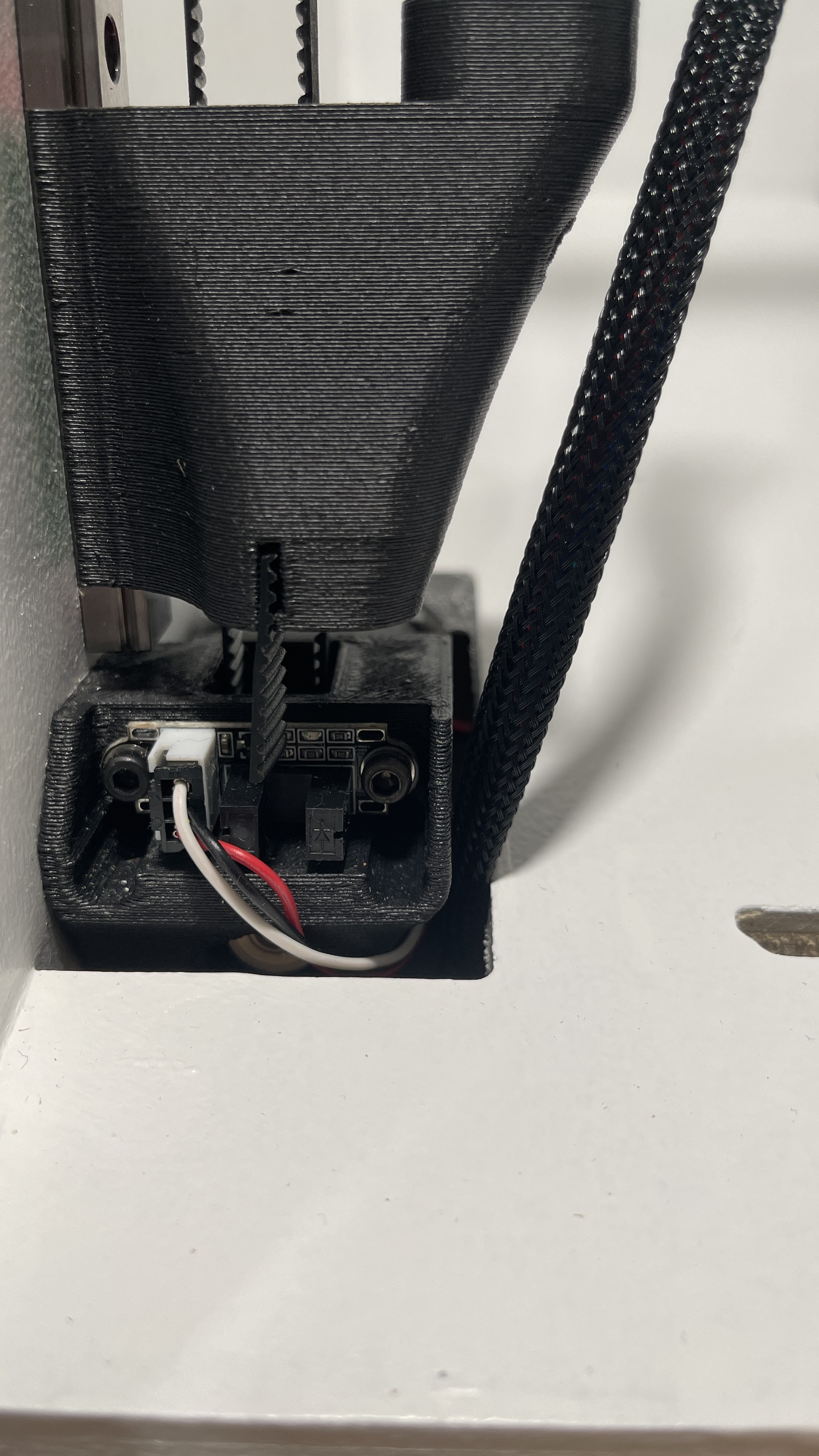
That wire though, it should either be on the stepper side or the switch side, none of them go over the side.
Not really.
I don’t beliave it is backwards, I tryed flip it over, no joy.
What wire? are you talking about the black wire sleeve? That is from the X axis and was just moved to take the picture.
I have some more pictures that I took before this trip and will add to my build thread later on today.
1 Like
Oh…gotcha, sorry I should have realized that.
Okay, I checked both of mine and they are lined up.
How thick are your linear rails and block? My stack is about 13.3mm bottom of rail to top of block.
1 Like
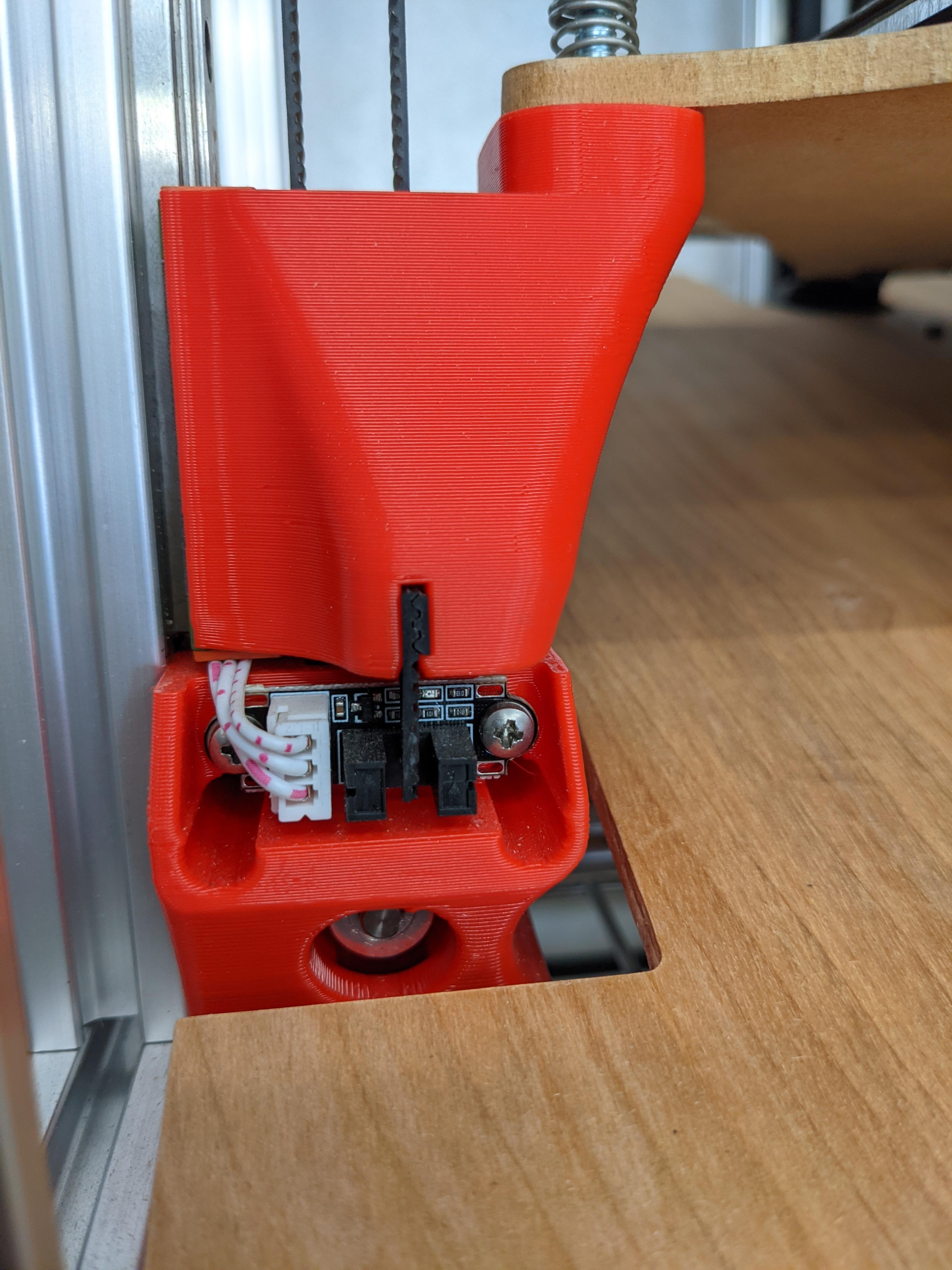
You are missing the little lock piece of belt in the mount. I have a small piece3-4 teeth long that locks the belt in from
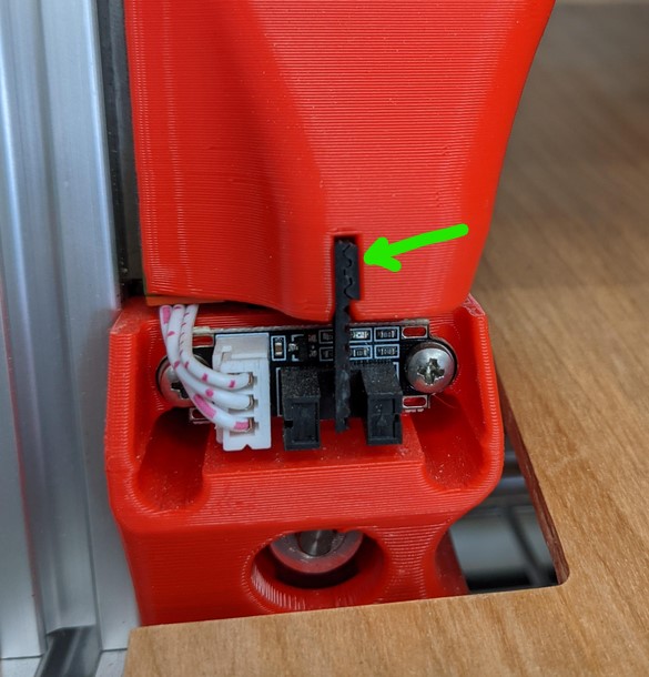
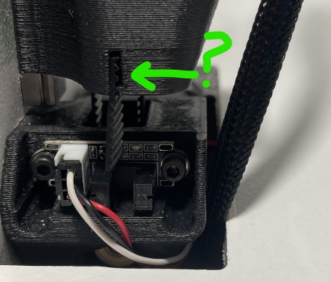
moving and keeps it straight.
2 Likes
I guess I see a little of that, but it has only caused a problem with the one sensor where it has hit the wiring. I moved the wiring and it’s been good.
For some reason I thought I have then in, I’ll be home tomorrow night and I will check everything.
It is possible, but If I’m not mistaken, I got them from the shop on my last order.
I suppose different switches might be possible, I did source mine from China, but the PCB patterns look the same…
Man This sucks, I have no idea how this can happen. Same linear motion thickness, same switches, same belt, same hardware. I can not imagine the printed parts being that far off.
How do all the belt triggers look?
I think the little strips of belt are an elegant solution, but have a possible low/no-cost workaround. In the past I’ve used cut off pieces of soda can for optical flags. It’s thin enough to cut with regular scissors. Hot glue it in the slot and it will take and hold a bend to fix any small alignment issues. You can also make it intentionally too long to start and then trim it to just the right length while testing.
1 Like
That might end up being plan B if we can’t figure this out.