I think that’s what I flashed. It’s the same UI as the Bart Dring laser/pen controller. Definitely not as slick as the Duet control, but plenty usable over wifi. Not having to sneakernet files to the printer is a huge usability bonus for me.
1 Like
Printing the passthrough pieces, and trying to figure out Fusion
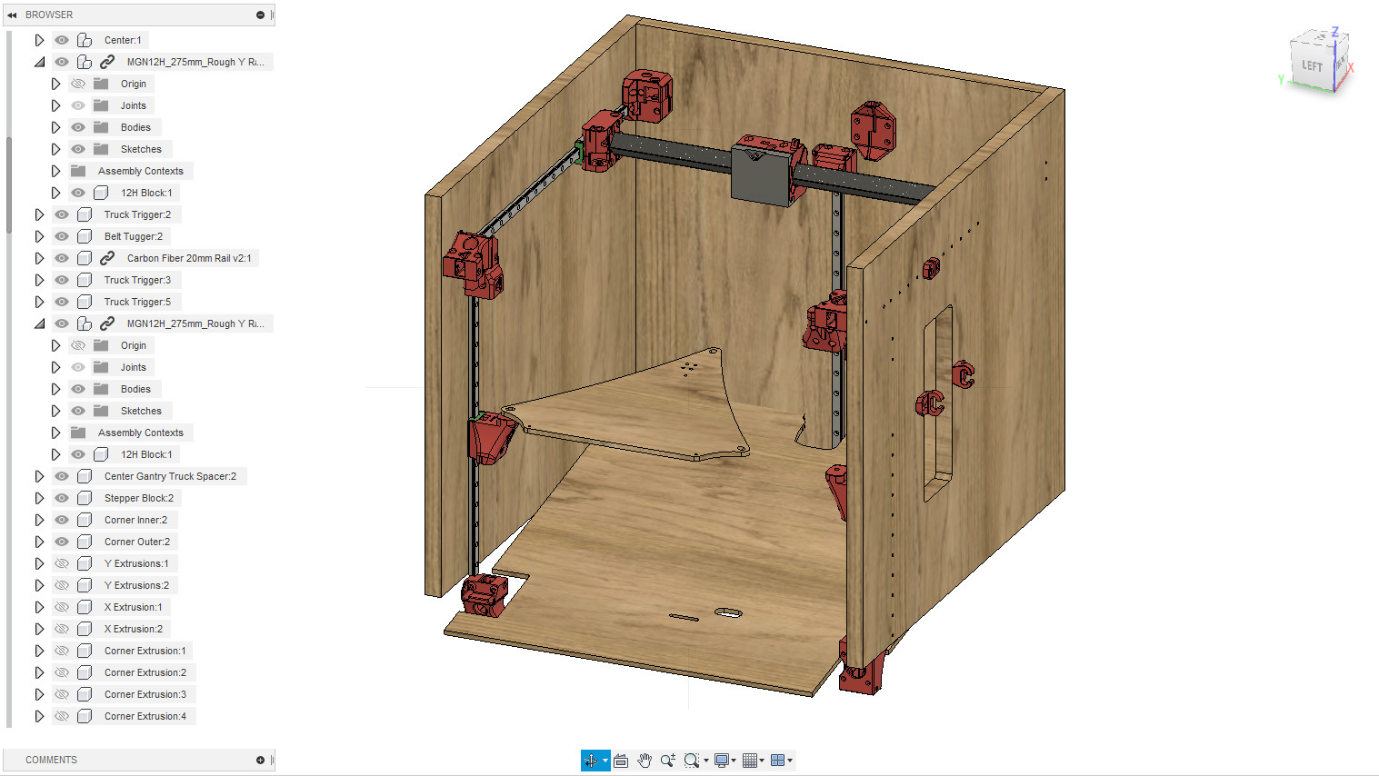
I can resize the MGN rails, but I can’t get it to change the assembled model. Pretty sure this means that I haven’t done the correct thing… well without the matching holes in the “wood” pieces of the model, it’s not that big a deal, it’s not like I can just pull a sketch of the sides and back off as a DXF and mill it.
The only pieces that matter that way are the build plate support and the wedge bottom. I would have liked to get those drawn up, but no panic.
Most of what I need is to make the right hand rail 20mm higher than the left hand rail when positioning the holes, and of course the associated holes for the motor mounts. The back corners look like they want both heights, though with extrusion they don’t get both at the sides.
Placement of the holes is still a bit uncertain. Assuming the 20mm spacing for where the extrusion would be is easy enough, though, I don’t think the back and sides are going to be difficult to draw.
1 Like
I added the holes into the wood sides earlier, did that work out.
When you change the rails, save, then update the assembly? For me it gives a warning to update.
Post a pic of what happens and maybe I can fix it. Another way to do it is walk it up in size slowly. 25mm at a time. Fusion seems to have weird errors sometimes, and just opening a bad sketch or constraint fixes it.
So, taking measurements from the Fusion assembly, and figuring out the constraints from there.
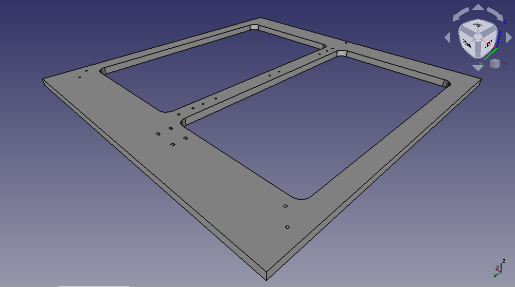
This panel would be the back of the printer. I might put some features into those large holes, I haven’t decided yet.
The top of this goes to the inside, and the “near” side is the top. (I drew it flat, instead of in it’s final orientation.)
This has the back panel mounts for the CoreXY corners, mounts for the Z rail (Using 6 of the screw holes, instead of all of them)
I moved the Extruder Umbilical mount to the left side, it was on the right in the model, because I intend to move the SKR Pro mount to suit its intended home. I’m not running a print farm, so stacking isn’t a concern.
I also extended the height to suit 350mm Z rails, and the width to suit a 320mm wide bed (300mm usable, but I don’t know the tolerances, so I stretched it 120mm.) I still show that I ought to have more than enough X rail with the 500mm length piece that has been “out for delivery” for 9 days and counting now. I’ll make some final adjustments to the drawing when the rail gets here, but I think this is about right. I might tweak the width after I see what the build plate support looks like with the Fusion model redimensioned.
For the sides, I’m trying to figure out what the important dimension is for where the side Z rails are placed. If it’s distance from the front motors, or that they form a proportioned triangle… (I haven’t measured those factors yet, so it’s all conjecture at this point.) Distance from the front is easy to copy, but an equilateral triangle also makes all sorts of sense from a suspension point of view. (I think that this is the case, actually, thinking back to looking at the mounting plate sketch) I’ll work with that as my premise anyhow., but then it all changes if I change the width. Maybe I’ll stretch the width to suit the 500mm rail, and let it be oversize. I’m not trying to make this fit into a small space, after all. The rail itself is such an insignificant mass, and I don’t see flex being that much of an issue for a few mm more… Well, maybe…
I’ll update the model again. The one I have doesn’t have them, but with resizing, I more or less have to re-draw everything anyhow. I’m sure it’s something that I’m not understanding right with the process, I’ll see if I cen get it figured out.
Edit: Yes, I see the holes now, along with the side spool holder pieces.
Re-edit: You’ve missed 2 holes for the umbilical in the back piece. (I made these 3mm slots to allow for the expansion/contraction around the cabling.)
Well…it doesn’t really matter too much you just have to clear the Steppers at the top so use my spacing from the motor mounts.
Nah, the bed leveling is set up to guess and check, you can set it to your exact dimensional offset to get there faster but…No big deal.
Also for the filament guide, this is to allow you to put the guide wherever you want, and the umbilical is so you can pinch it to fit your wires and drill your own holes…but you are right slots make more sense. Good catch.
If you let me know what you want for dimensions I can adjust it on my side and give you a version number to work off of.
I am trying to get the basics in before I do anything fancy. I am just trying to decide how to work the wedge. I am going to go thicker and use it as a structural piece on the wood build, the extrusion build it is just for show.
1 Like
I was itching to cut the wood or plastic pieces today but I am not ready yet.
1 Like
Good plan.
Aha! I think I figured out what I was doing wrong.
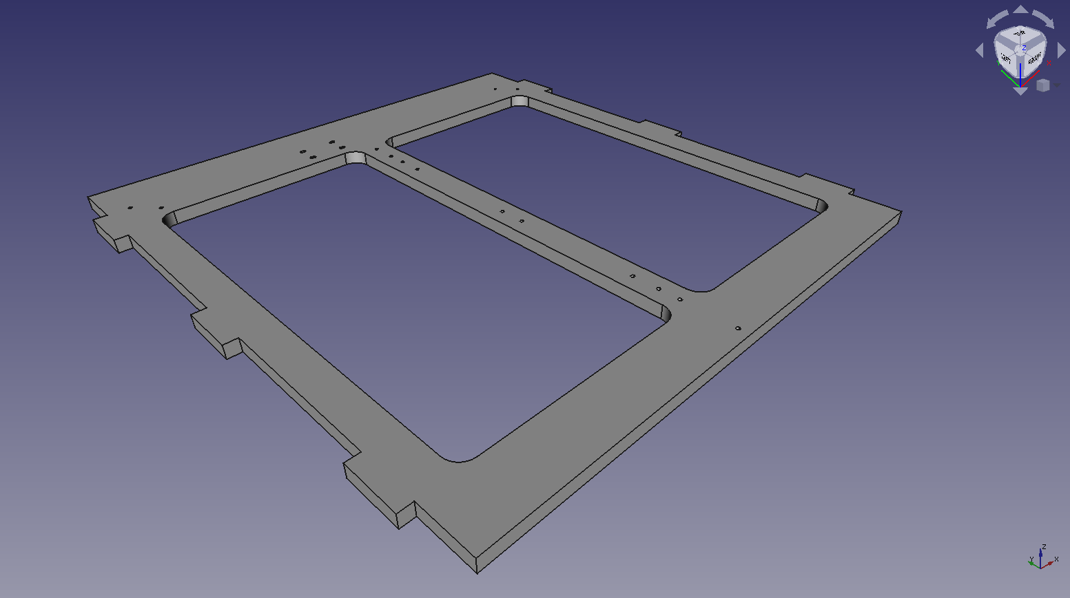
Not complaining! Please consider this sort of a “beta report” for the Fusion model. I am sure that I can work with the model as it was, The bed support is giving me the biggest problems so far. as I’m trying to measure the mounting stuff for my headed bed and figure the measurements. I’m showing that the Z supports center 50mm from the inner wall, so from that I can calculate the hole positions for the mounting slots, which are angled 120° apart on your model, so I’ll do the same.
OK. But since I’m doing the work anyway, I’ll aim for close to equilateral, then fudge it a bit to round to nearest 10mm for placement of the Z rails… Unless this puts the Z rails in a stupid place, then I’ll have to rethink. It’s still a square bed, so it should be reasonable, I think. I just need to nail down some other dimensions.
Some funkiness…
(cumulative effects)
Lengthening the Y rails:
The sides don’t get all of the mounting holes for the longer Y rail, and the mounting platform didn’t stay with the back mount. (I kind of feel that that should have happened, and the side Z rails should have retained their position relative to the back… but that’s asking a lot of Fusion to recompute the bed support, given that drawing.
Lengthening the X axis:
The wedge kind of blew up here… But then it fixed itself when I lengthened the Z axis, so this actually worked really well. I stretched the CF rail by 120mm.
Lengthening the Z axis:
It didn’t lengthen the sides, and pushed the motor mounts off of the bottom. Again, didn’t increase number of holes to match the new model.
Interesting enough, it deals with shorter rails quite nicely, without adding extra holes. (I tried it with the Z rails to see what would happen.) So that’s cool.
However, the sketches I pulled re-affirmed my measurements, and I was able to take a couple more meaningful measurements from the whole thing, so it was really useful to update the model.
I’m having a ton of fun with this as a project, even moreso because of the changes. I have to put lots of thought into which measurements stay as is, and relative to what.
Since the bed plate doesn’t scale, and seeing as how I have to redesign it all anyway (If I want to use the part I bought)
Your suggestion was to keep the front edge the same. I presume that this is where the printer homes with the Hemera mounted to the hub. It occurs to me that the back edge is also important that the hotend can reach it. I’m thinking that I actually have a fair amount of extra to play with in the Y axis, and since nozzle drool has been a thorn in my side before. I’m thinking of adding a wiper. I can either add this in the front corner, or in the rear, but I’m thinking that if I put it under the home position, and (for example) define the Y endstop to be at Y=-20, my 0, 0 location can still be the corner of the build plate. Because the nozzle doesn’t move in the Z direction, it should be a simple matter to implement a wiper at the home location, and it won’t get in the way of printing.
I’ve been thinking a bit about aesthetics, and I’m planning to put a front plate on. This will keep the wedge part so that it isn’t really structural, but it will help enforce squareness. I also plan on adding a top cutout frame to keep the top square, so there will be 6 panels in all. I’m playing with the idea of making it a tabbed box, but if I do that, I’ll need to spend more time dialling in the LR before I start cutting wood. Not that this is a bad thing.
I’ve decided to hold off on printing the LCD control box. I’ll make that the printer’s first project instead.
Come to think of it, I still need to reprint that center section for the LR. I have the very first version where the reset hole is offset a couple of mm. Also, my white filament is a little translucent, so the LEDs make the whole case glow…
The further apart the rails are, the more accurate the leveling can be.
Makes sense, the holes don’t exist to move but can be added in the side plate sketch. I should go in and name them for easy editing.
It worked when I tried it. Did you only do one axis per refresh? This is also one of those things that I bet you need to open the sketch to edit and it snaps into place. I have it dependent on the projection of the z lifter holes only. I will have to try this again.
Might need to take it in smaller 20-25mm steps. I had that happen when it wrapped a circle the wrong way, tried it a second time and it worked.
Yeah the way this model is built the corner extrusions (and wood sides) were in place before the Z axis so they are hard coded lengths, you only need to edit the first one though. I MIGHT try to rebuild the model to solve this.
Welcome to my world!!
For the hemera the left (more home position) there is plenty of room. You can move the bed on the bed plate to adjust if you need to. I think it is set to the edge of my bed 214x214. The bed can be asymmetric though, so if you leave room and drill teh mounting holes later you can leave room wherever you want.
that is my game plan, probably for the wedge as well.
I think you might want to wait. The forces on this are only the belt tension. Nothing else really gets loaded much. I am going to go solid with the wedge, no bottom and as a backup I am going to use a tiny CF tube(old arrow shaft) to hold the top of the frame the right distance above the steppers (or in front). Maybe leave room for it, but I really doubt it is needed if you use 1/2" material or more. The only reason it might be needed is my ply is kinda bent, so if the tabs do not hold it straight I will add some small gussets, probably printed.
1 Like
Are you using a cr10 sized bed? I think the screws are 200mm on center and the bed is 310mmx310mm. So it is 55mm or so from center to edge. But at that size, printing 300 mm area is pretty good already.
Yes, I only did the one axis per. I remember you saying I’d have to extend the corner extrusion, (Well, now I remember.)
The wedge was OK after I lengthened the Z axis… Then when I shrunk it again, so not really worried about that one.
For the top cutout… My reason for this is that the seasonal variations in humidity around here are extreme. In the summer, humidity goes pretty high, and int he winter it’s extremely low. It’s not kind to unfinished wood. Some sort of finish on this box is probably a necessity.
I also want to put a front on it, underneath the wedge at least. I intend to put the power entry/switch there, because it makes sense for the intended space. (Probably doesn’t matter, my printers tend to live powered up all the time. Besides a front is a perfect place to have some fun with the laser ![]() I’ll hold off on the top for the time being though, I’m sure you’re right and it’s not needed.
I’ll hold off on the top for the time being though, I’m sure you’re right and it’s not needed.
I measure the screws for this as 240mm on center, but I think it’s supposed to be CR10 sized.
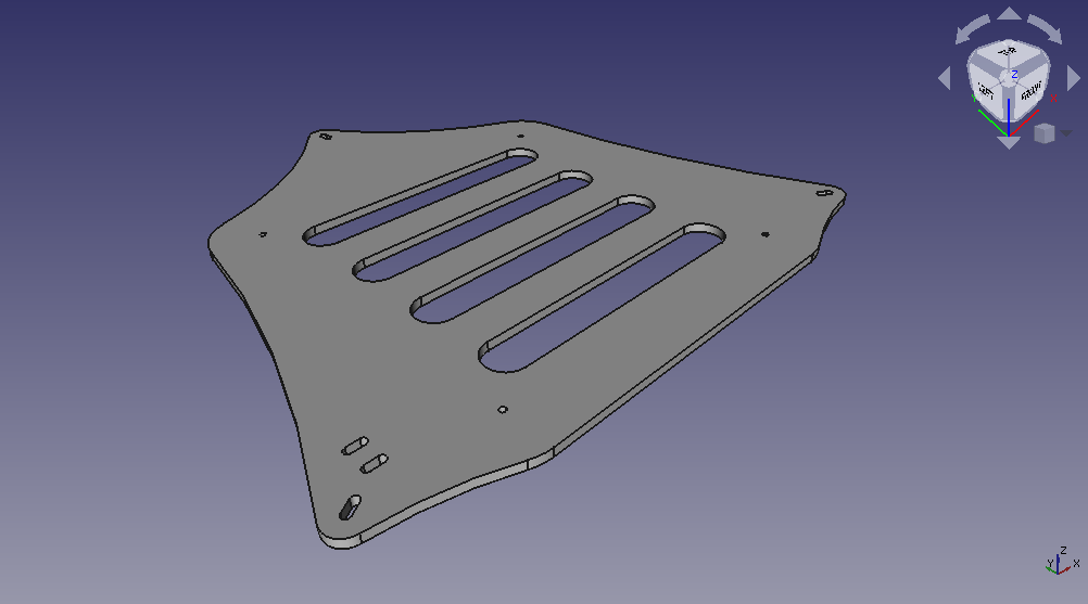
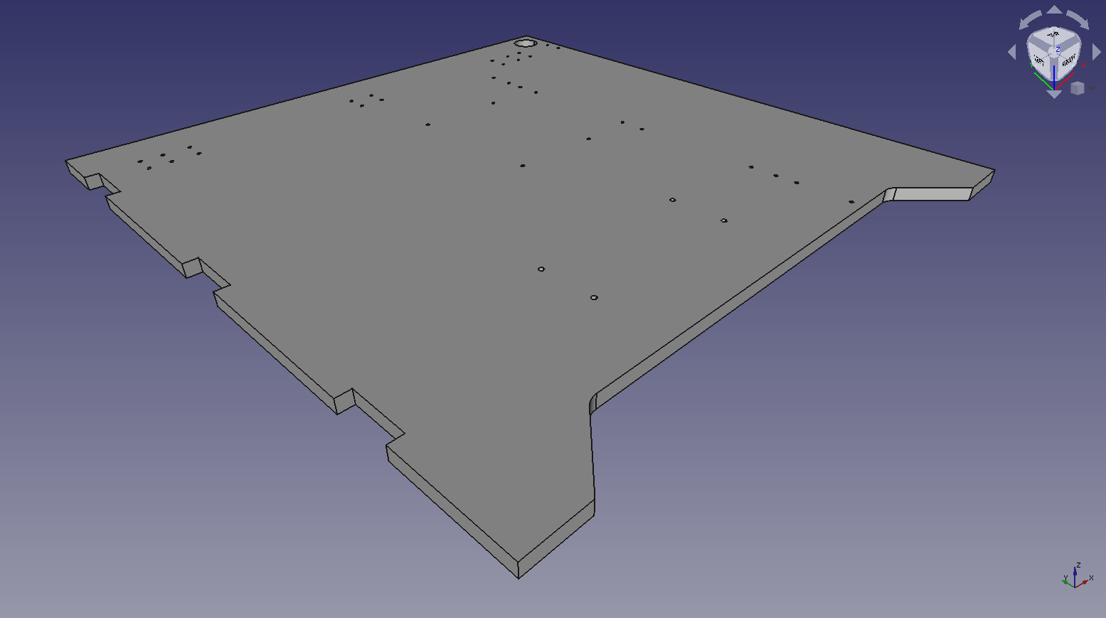
This monstrosity is what I came up with for a support. I decided to keep the back edge of the build platform at the same distance from the back plane as Ryan’s model. This will give me extra space to the front, but ensure that I am able to get all the way to the back of the bed. I’m still leaving room for adjustment. I can change one parameter on the sketch and move the bed forward up another 30mm or so before the sketch breaks.
2 Likes
So I drew up a side panel as well, and altered the back panel for a tabbed box design. I just went with 3 tabs, but it would be really simple to update that to 5, since the space between is exactly 3x the length of the tabs. I think that this will be secure enough. I am considering adding screw holes in the center of the tabs, too.
I’m going to assume that I’ll build these panels out of the 12mm plywood, since that’s what I have, and that’s the length of the tabs.
The sides have 2 sets of holes for the motor mount and linear rail, I’ll cut both sides differently, but I see no need to redo the common artwork.
The front panel will mostly be a frame with a marquee over the top and a panel at the bottom for the power entry and switch.
2 Likes
I tabbed up the wood in the CAD, and started cutting. Ran to the hardware store…the HDPE I got was cheaper than decent plywood, go figure. So I am cutting the first one out of HDPE. After it is proven I will swap to the the “expensive” Plywood build.
I made the mistake of cutting the Bed plate bed mounting holes too big, I will check the CAD but my rivnuts came in handy, just expanded them in the hole and they fit perfect.
2 Likes
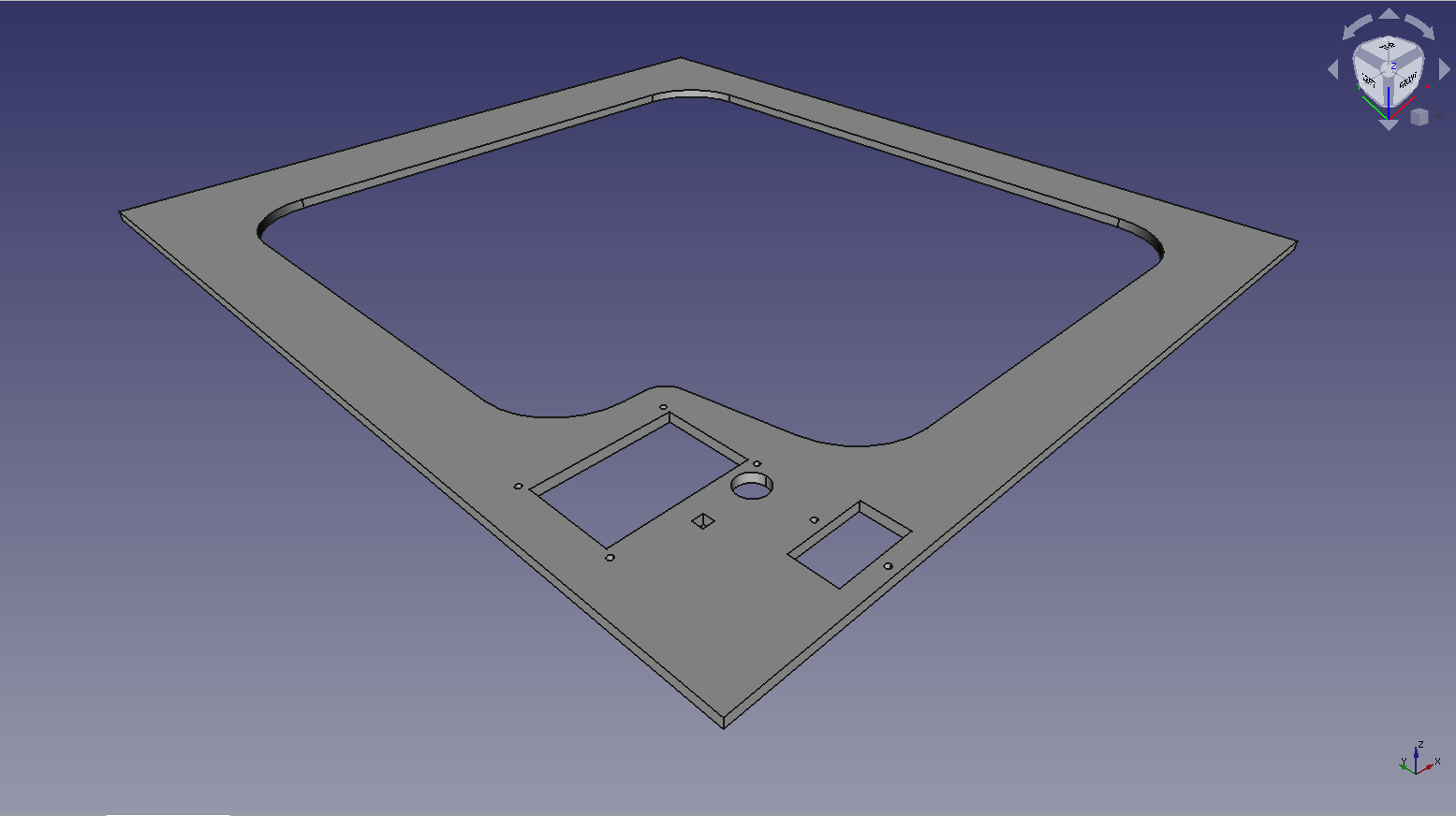
Change of plans for the front panel… I think that this will mount the TFT in the lower left corner. I should just need some nylon washers for the mounting screws. Mounting on the left here allows access to the SD card and USB port
Now, if only I understood how to do assemblies in FreeCad, I could show the intended enclosure. Well, if all else fails, I can import them into TinkerCAD, lol.
2 Likes
Well, you can show us in real life once it is installed 
3 Likes
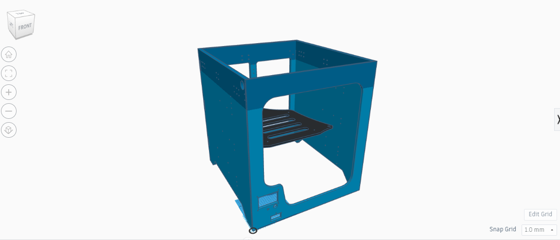
Yeah… TinkerCAD thinks it’s too big, so it renders funny. Even this rudimentary placement is helpful for my visualization though. It gives me a better understanding of how it’s going to look when finished.
The 450mm Y rails are really too long. If I hadn’t already bought them ages ago, I’d have been good with 400mm, probably even 375.
I also strongly suspect that I’ll never use the full build volume on this thing, as a back-of-the-napkin calculation shows that it would be pretty easy to use a full 1kg spool of filament in this thing. Maybe I should invest in a run-out sensor, though I’m out of endstop inputs to connect it to, lol.
Before I cut out that front plate, I’m going to do a test cut for just the TFT in some 1/4" foam. That’s a 2’ chunk of material, and I don’t want to waste that much.
I cut mine on a little abrasive saw.
Oh no…I wanted to use one as well. I am sure there are spare pins on the SKR, I will figure that out for sure.
1 Like
You need to make sure it clears the bed. I might be able to help by measuring mine.
ell, that’s the “advantage” to those extra long rails. I’ve got more than 50mm at the front of the printer for bed clearance.
I did consider that. Not like it would be difficult, and I still have time to adjust the CAD… but I think I’m going to end up using that movement for the nozzle wiper, and the TFT home. This thing is going to be somewhat of a behemoth.
I did just realize that with the 12mm side and back panels, the M3x10mm screws that I have afren’t going to cut it for mounting stuff, so I ordered 100 each of M3x20mm and M3x25mm.
If I measured right, the screw pads for the printed parts are 5mm thick, and 3mm thick for the rails. That makes the rail mounts 3mm + 12mm = 15mm so 20mm screws ought to have enough to put a locknut on them. The printed parts are 5mm + 12mm = 17mm. 20mm screws are probably ok, but I’ll have the 25mm screws to be sure.
I left a provision for the 50X150mm spacing for the power supply mount, and for the 86.5x138mm spacing for the SKR Pro on the left hand side panel, as well as a pass-through for the wiring to get to the alpha and beta motors and endstops. It occurs to me that I probably should have put the slots for the umbilical connector on the left hand side panel, too. I think there might have been a reason that I didn’t do that, but I can’t remember what it was.
1 Like
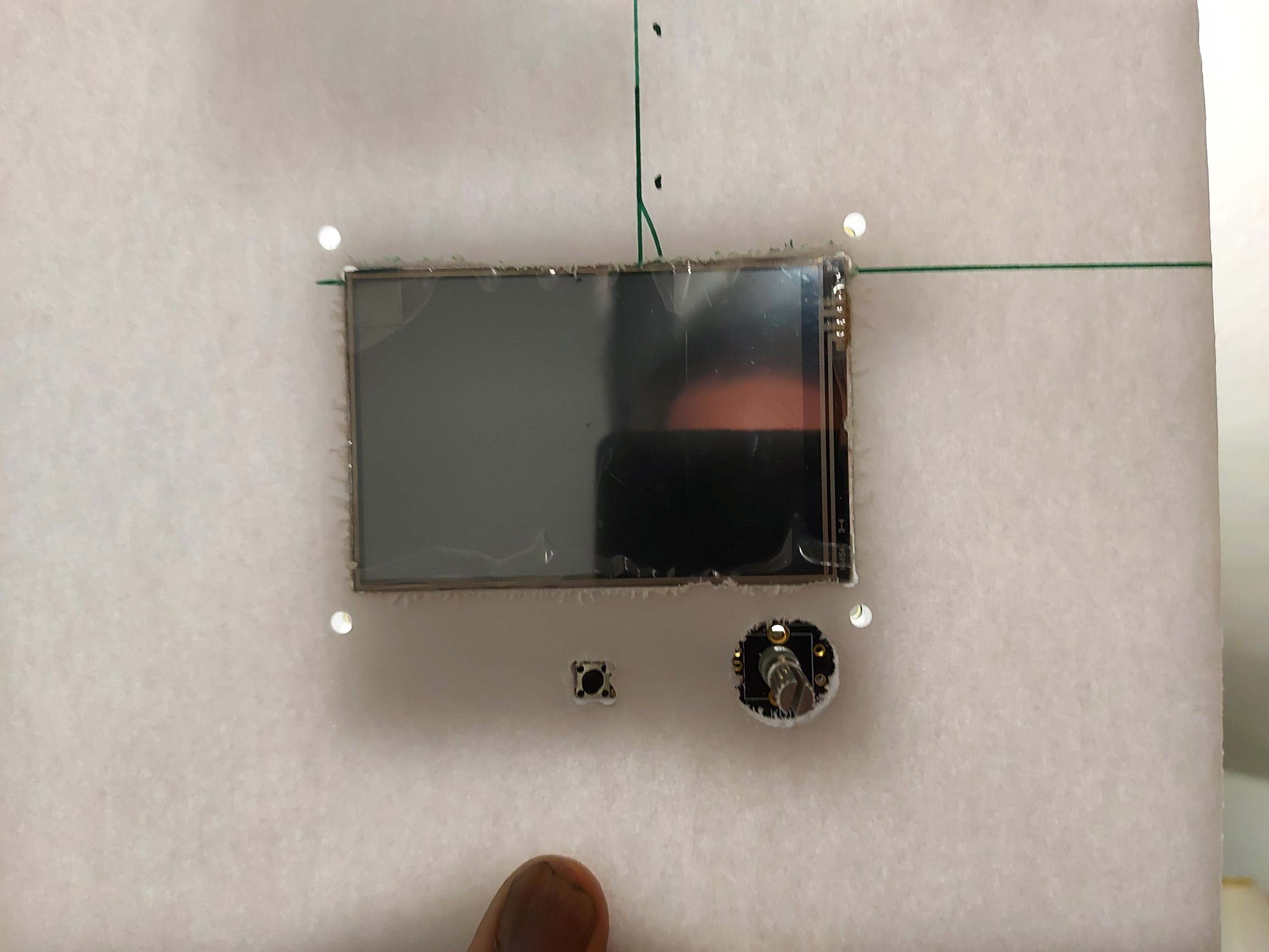
Test cut in foam for the TFT cutout. The mount holes look perfect. The screen is a snug fit, I’m sure that a touch of sandpaper would be more than adequate, though I don’t intend to bring it that far forward, I’ll use mounting spacers to set it back a little, the screen should be more or less flush with the back edge of the front face, which will give room for the encoder button.
2 Likes
I had an idea for a 3D printer insert - like if you laid the screen on the surface and dropped a sheet over it. That would give you acces to the SD and USB ports. You might want to make the edge closer to get to them, unless you plan on 100% wireless transfers.
1 Like