into a single Fusion 360 document. As I’m going to be limited to 10 active docs shortly, I want to be ready.
As a new Fusion 360 noob user I have created separate documents for these and have copied around the dimensions between them. I am now realising that this was a mistake, possibly a big one, and I am trying to rationalise this and have them all in a single document with each element a component, which is I think the right way to do it.
I can create components and sketches for each of them and can see that we have an object hierarchy.
What I want to do is to have the main dimensions in a sketch at the top of the component hierarchy and then for each component to use and extend that sketch, so the top plate and bottom plate are very similar but are extruded differently. The dust shoe will connect to the glued top and bottom plate.
I don’t want to create a massive single sketch at the top level and then try and pick through which bits get extruded for each sub-component and which don’t get extruded. I’ve created sketches at each level and tried to connect to points on the main sketch at the top of the sketch hierarchy but I can’t connect or snap to them. I can visually align to the main sketch, but I don’t don’t think that’s the right approach.
I can also copy the main sketch into the sub components and use that, but if I change the top level sketch, the changes aren’t propagated through. As far as I can see, sketches appear to be independent of each other. I think this is what I need to find out, can sketches link, connect, or work with other sketches.
I’m not sure if I have explained this correctly but assuming I have, is what I want to do possible or not?
As Derek suggested, the Project Sketch allows you to “copy” geometry from one sketch to another. As long as the “Project Link” is checked when you do the projection, any changes to the original sketch will be reflected into sketches where you’ve projected that geometry. Certain kinds of changes to the original sketch can break this link and you will have to go back and cleanup (re-project) geometry in the sketches.
If you are only interested in values rather than actual geometry, User Parameters are a better choice. You can give a value a name and then use that name instead of the value in all your sketches. Change the value associated with that name and the value changes in all of your sketches. Actually User Parameters can be used anywhere, not just sketches…for example the distance in an extrude.
Open one file then open a second using the “Insert into current design” function. You still retain each part information that way and only have one item. However, not sure if the merge of two into one counts as one document or two under Autodesk rules.
Thanks for the replies. I will look at the Project Sketch and try and work my way through it.
I have used the parameters quite a lot for making simple p-clips and CNC clamps. The issue (for me) is the drawing becomes very difficult to follow as there are so many lines.
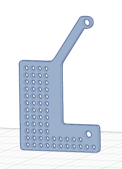
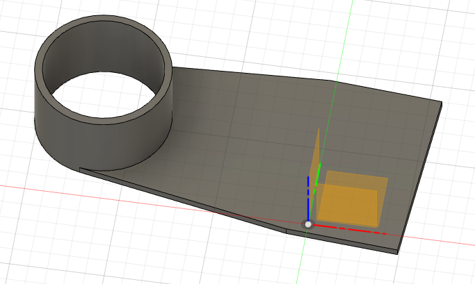
A bottom plate. I print this in two parts as I wanted a clean channel for the air and dust to be sucked through. Adding in supports clogs the channel. This will be glued to the top plate.
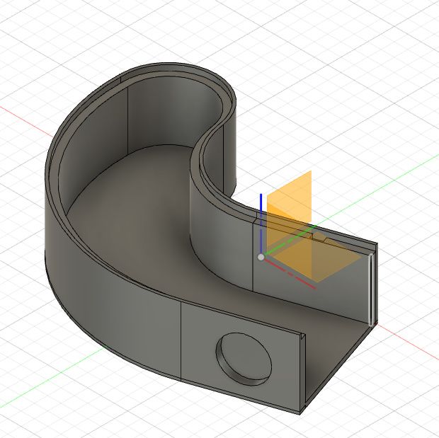
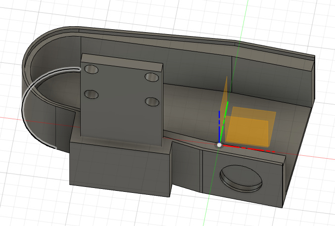
A removable dust shoe. The holes on the sides are for magnets. I know this design isn’t quite right as some of the dimensions and lines aren’t quite right. This will slide onto the glued top and bottom plate.
At the moment thought all the components are extruded into new components but from a single drawing held at the top level. There are no sketches/drawings held at the component level.
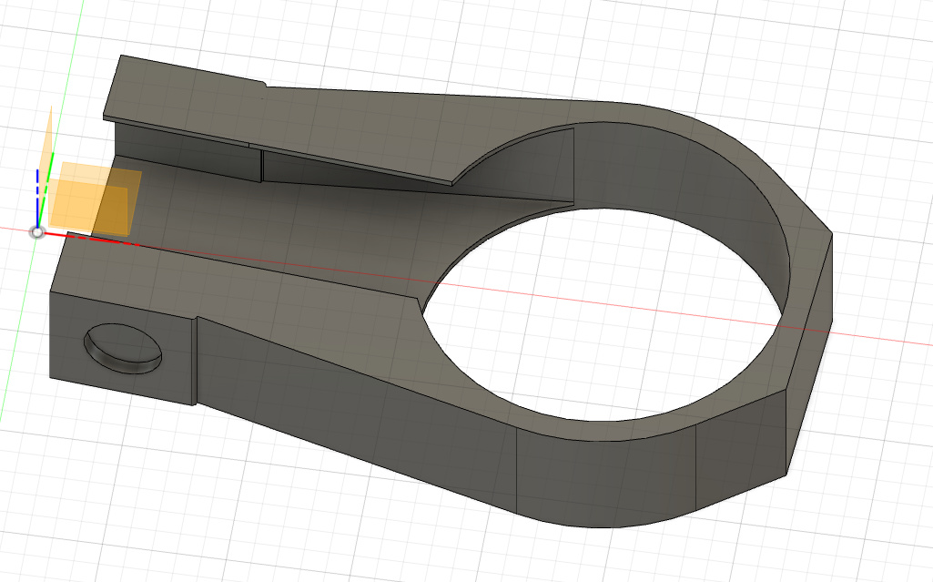
The issue is the interface where the dust show slides into the joined bottom and top plates. It’s a mess in the drawing and I have to think very hard what I extrude. It is entirely probable I don’t know Fusion 360 well enough and there are simple ways to manage this.
I’m no CAD wizard but have worked with quite a few, I find it fascinating how they can visualize an object and work out the best design strategies so quickly. It’s partly learning the tools but some people have really good 3D spacial awareness.
I’m a frequent Fusion 360 user, but everything I know I’ve learned from internet videos. I often wish I had at least some professional training so I would know the right way to do things. With this as context, I’m going to suggest how I might approach this problem.
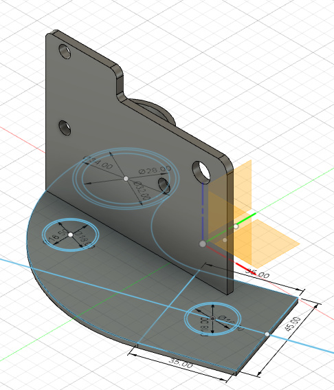
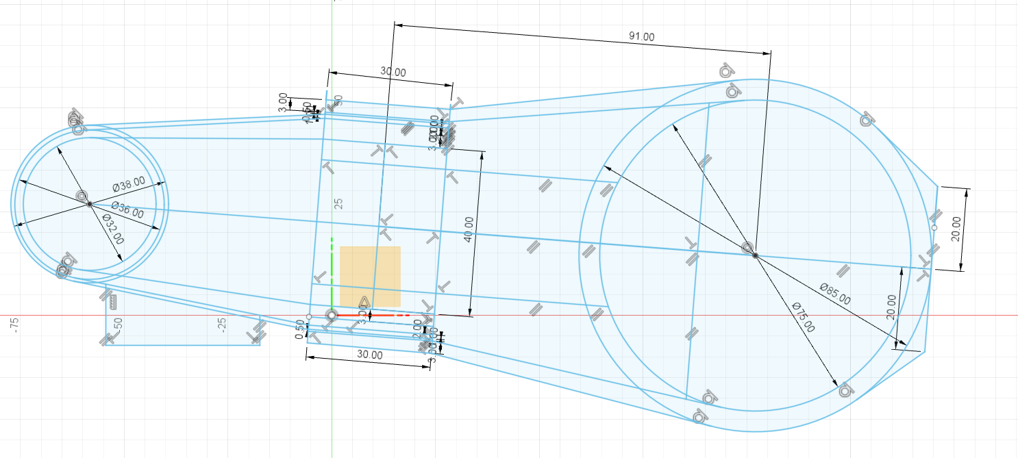
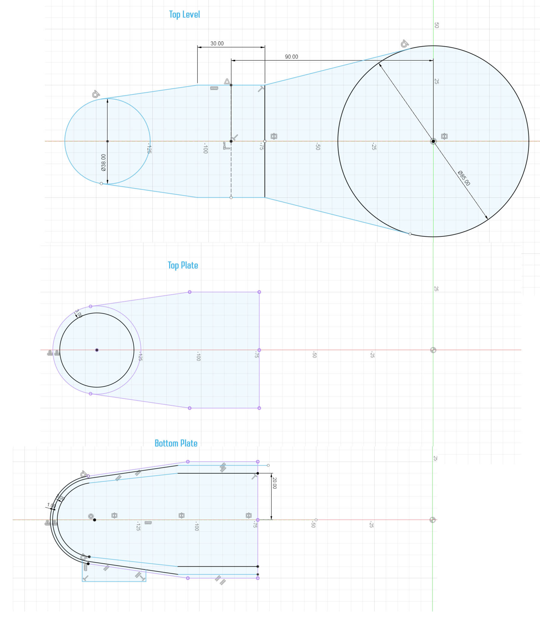
The top level would contain a much simplified drawing. It would contain the largest circle circle at each end, the sides (not including the right angle bracket), and the one bisecting line that is the end of the first two parts. I might establish User Parameters for the diameters of the two circles. If there are other critical measurements like the distance between the two circles, I might make them User Parameters also.
To create the ‘top plate’ in a new sub-component, I would Sketch/Project into a drawing in this sub-component the outline of just this part from the top level drawing then offset of the circle to create the pipe. Note I would only project the lines I need, not all the lines in the top level drawing.
Similarly bottom plate sub-component, I’d project the same lines as I used for the top plate, then draw in the rest of the needed lines relative to that outline.
And for the shoe (in its own sub-component), I’d project the other end of the drawing up until the overlap between the shoe and the other pieces end, and then define the rest of the part.
Thats exactly what I am trying to work out how to do. I’m in much the same boat as you and have learnt from internet videos rather than on the job. I have taught C and Unix development as I used to be a UNIX developer and having somebody teach you face to face is so different than following a video. Trying to explain setjmp or how to access pointers on a stack is difficult to understand, face to face is so much easier as everybody has their own internal models of how things work.
The Sketch/Project appears to be the way to do it, I’m trying to find out what to really do. The other issue is that the 3d printer is never as accurate as you want to be, so making things that slide in tight but not too tight is tricky.
I’m hoping I can do all of this in one file rather than having different files as I suspect my 10 file limit will hit soon
Yes. And the Sketch/Project works with more than just sketches. You can project aspects of 3D geometry. For example you can create one object and then use the edges of that object in a new sketch. And if the original object changes, the projected geometry changes in the sketch, which in turn can change the 3D model of something that is created from that new sketch.
There are a couple of downsides. It is possible to modify the original model or sketch in such a way that it breaks the link to the project geometry. Then you have to go fix things up, which can be a slog. The second more minor issue is that updating can take some time since a minor change in one place can have an impact in a lot of different places in the file.