This is not made yet, but the start of a build log for a laser engraver. Rather than getting off tangent too much from LowRider-inspired Foam Ripper , I am starting a new topic here. I am initially starting with Mike’s design as shown in the thread message above, but who knows what it will end up looking like. Mike’s design is mentioned in that thread & included here also for easier reference: located: https://www.modelflying.co.uk/forums/postings.asp?th=147510
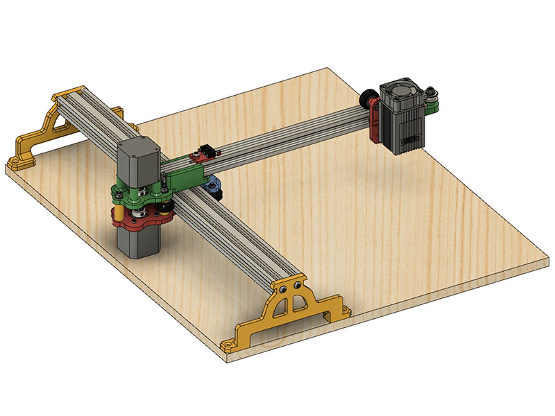
The end plates I will probably end up using 250mm lengths of 2060 or 2080’s, but have assembled all the parts from the original build as a starting point. I did find a couple of dimensions for the wheel holes so far that were not consistent in the bottom & top frame, so I adjusted them. They were about .5mm off of being parallel with the V-slot. I was originally thinking of using eccentric spacers for the main beam, but that would require 4. Mike pointed out in the other thread that the eccentrics might take that cantilever out of square. If they are adjusted equally & check square while adjusting, should be able to use them. After fitting Mike’s wheel adjustment 3d parts I am kind of like that method. I also plan to use the low profile screws from openbuilds instead of the flat head screws, so I adjusted the countersunk holes as needed. I assembled the parts in fusion 360 using the .123dx files from Mike’s design, a 5500mw laser model from grabcad (https://grabcad.com/library/laser-diode-5500mw-1) & a limit switch from grabcad (https://grabcad.com/library/limit-switch-10t85-gsfy-10-1). The 2040 is 500mm length & the 2020 is 360mm in length in this design. That should give me at least 400x200mm or more of burning room. I am currently planning to use a 6 watt diode laser with this design.
I was originally going to use short 2060 or 2080’s on the ends, but kind of like Mike’s idea & decided to combine his foot & pad as one part for simpler assembly. I also rounded the inside edges because I plan to add a belt tensioner on each end. Not sure how the belt tensioner will look yet but should be fairly easy. The rounding extends further down to just make it look better. I just realized that bottom weld & other spots could use some rounding, so will add that. Here is an image with a short 100mm 2040 so you can see both sides of the foot better.
Are you not afraid of the changes of weight when the head moves back and forth?
If there is a tiny amount of slop the laser will not be vertical but be off with a few degrees.
This is based on a design that already works, so there should not be a problem there as long as the cantilever is not too much. Sorry, I forgot to include the link of the original design in this thread. It was mentioned in the previous thread & I just added it to 1st message for easier reference. Thanks for prompting me to add it. Take a look at the 2nd link in the 1st message now that I added it.
I changed the top plate that connects to the 2020 by adding 2 - M5 screws with T-Nuts on each side instead of just 2 - M5 screws with T-Nuts underneath. Changing the M5 locations and having 4 instead of 2 seems like that should help with structure. I also do not need low profile screws for those locations. Oops, I just realized I can’t do that because the belt goes thru the areas of where those M5 screws are now connected. I could change the location of that belt to above the 2020 cantilever like I have on my rolling plotter design, but the next idea would have to be changed if that could possibly work.
I had an idea to extend the cantilever, so I had to draw it up. After looking at it, seems like it will still put stress on the wheels with longer length. My idea is to connect a short 2020 vertically where the 2020 sits on the 2040 which is drawn at 100mm length and add some sort of cable to connect the end of cantilever to the top of the 2020. I drew this using 2 simple L brackets & a GT2 timing belt as the cable. I would add some sort of belt tensioner to get it tight. This does complicate the design more. Probably would be better off adding more counterweight to where the motors live. Would this idea have any chance of working?
I think all that mod will do is help prevent the 2020 from bending, it is doing nothing to relieve any sideways pressure on the wheel to track bearing surface. The mass of the laser assembly is not enough to deform the extrusion, if you really wanted to ‘fix’ the height of the boom at its outboard end then I would have thought a leg going down from the end of the boom to a roller on the base board would achieve that…a simple roller should be possible without introducing noticeable left-right drag I would have thought…not sure it is necessary though…I have never noticed any appreciable sag in the boom.
A wheel could work, but depending on what you were working on, it might introduce new problems. Specifically, smearing the work, or moving it (if it was delicate paper or fabric).
You could also just scoot the other two motors back a little, but then you’d run into issues where the gantry might tip that way instead.
I think it probably makes sense to just leave it constantly tipping towards the laser, and any backlash would be always at one end. Then adjust the feet to make that arm level with the workpiece. If it ever completely tips towards the laser side, then you need a wider base. But since there is so much weight in those two motors and the main rail, I wouldn’t expect that to happen unless the gantry arm was really long.
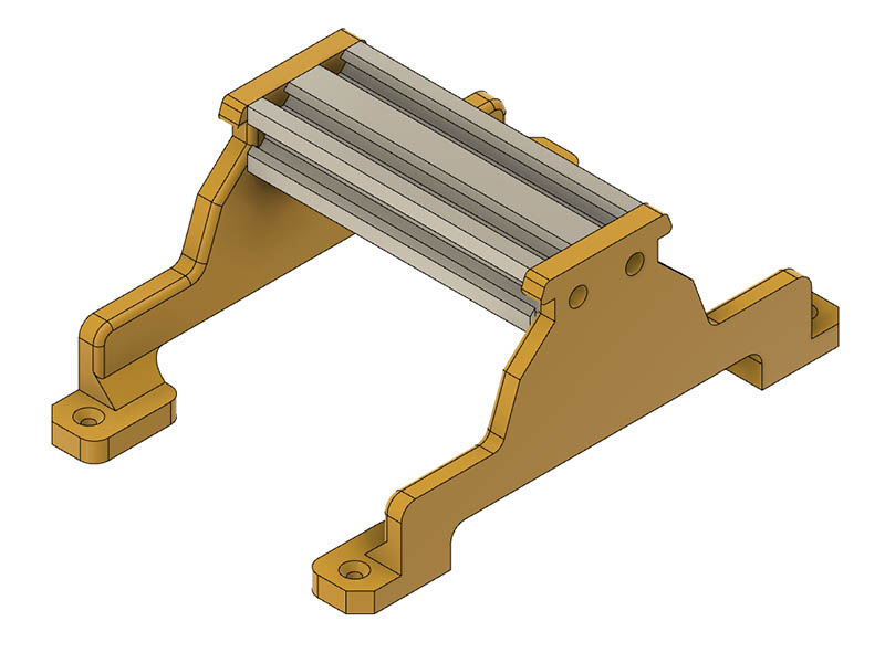
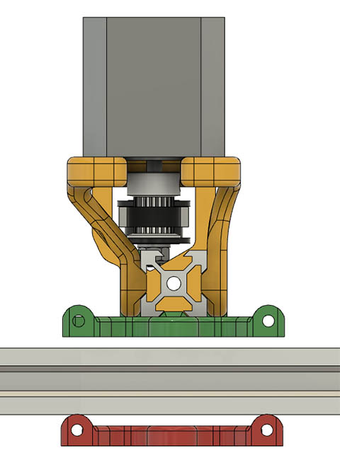
Thanks for the replies, Mike & Jeffeb3. I am just overthinking it. I will leave that part of the design as is. I did change the top plate to have 6mm thickness on each side of 2020 since that is generally what I have used in the past. That might help a little bit for stronger structure. I also had to increase the height of the end feet as my motors are about 44mm high. Another thing with the motor mounts. There were slotted holes there before & I made them just holes since I will plan to tension the belt at the ends. Instead of nuts on the long M5 screws holding top & bottom plate, I made SPACERS which are shown in yellow.
Mike, I was looking at your wheel adjustment plastic parts on the 2040. Are you using a screw & captive nut between them to tighten them in? Looks like that from the design, but I did not see mention of it in your build log.
Yes, an M3 bolt goes into one of the adjusters with a nut recessed into the ‘mating’ surface which allows the bolt to push against the other adjuster which has a very small hole in it to provide 3 boundary rings as reinforcements.! Primative but it works.
The slotted holes for the motor were not to tension the belt, they were just to allow a tolerance for the motor mounting hole spacing, I tensioned the belt with a Tnut and screw at either end of the beam.
Thanks for the info. I like your M3 wheel tensioning idea & drilling the small hole to create perimeters for more strength. I thought all Nema 17 motors had a 31mm distance between holes? All the one’s I have are that way, so will leave it as a hole rather than slot. I will redraw your wheel tensioners as my washers that should be a press fit will probably be a little different diameter than yours.
How long is the 2020 you are using? In your build log you mention using 40cm, but your assembly drawing measures 36cm. Were you able to put a 40cm 2020 on there?
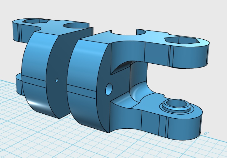
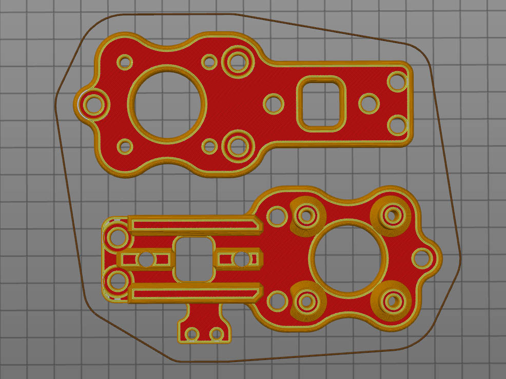
I made some more minor changes to the feet & Motor Plates. I cut out some plastic on both & seems like it shouldn’t cut any structure from the design. I may still have to adjust the height of the Feet, but will assemble Motor plates before deciding that. On the motor plates, I also moved the back M5 holes so the bolt would not be partially hidden by the motor. I have not made any changes to the laser carriage yet and may not use that. I attached a plate of the STL files I changed in case anyone wishes to take a look or critique them. I have not printed any of these yet, but these should all print without supports. I also attached a screen shot of the current assembly.
Looking good…the hole in the second tension adjuster looks a bit big…it looks like a 3mm bolt will fit through it instead of just being enough to force the slicer to include outer layers…
Are you intending to use low profile heads instead of csk as the adjusters axles because the heads must be flush with the top of the upper frame as the cantilever arm sits on top of the bolt heads.
I mounted the controller PCB at the rear of the frames so needed the back to be flat and the rear post to be where it was but if you are mounting the PCB elsewhere…
Keep in mind the weight on the laser carriage if you intend using one of the openbuilds ali plates…the eccentrics, nuts and bolts all add up.
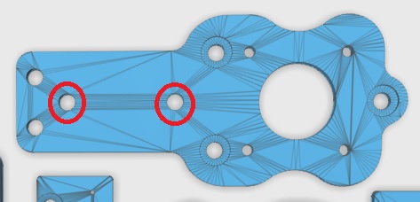
What are the circled holes for?
Thanks for catching M3 hole. I was mirroring the part & forgot to fix that. The holes in the bottom plate are for allen wrench access in case I need to get to those screws easier without taking the bottom plate off. Those holes also add extra perimeters in there which should give it a little more strength. I am using openbuilds low profile M5 screws for the screws that need to be countersunk. https://openbuildspartstore.com/low-profile-screws-m5-10-pack/ . I meant to ask you what those horizontal holes were on the back of the plate. That is a really good idea putting it there & gives it a little more counter balance weight. I will have to add those when I decide on the board to use. That will make the motor & limit switch wires really short. Guess I could always add the holes & use a transition plate mount to the electronics board. I currently plan to get the EleksMaker® Mana 3 Axis Stepper Motor Driver Board Controller. Guess I need to decide for sure which board to use. I have a keystudio CNC Shield V4.0 as well as an arduino uno with a cnc shield on hand.
I was thinking about how much weight is on the end. Looks like the 7w laser will be 155grams(4.05oz). The 3d printed 4 wheel carriage I have for my rolling plotter is 3.8oz with 4 wheels. A wheel assembly is about .7oz, so it is worth going to 3 wheels. I should be able to keep the weight below 8oz. Do you know what the focus height of these lasers are? Looks like your carriage will be the best idea for cutting down the weight. I may have to change the mounting hole height depending on how far I can focus it.
I also made another cutout in the plates between T-Nut holes. This cuts down on plastic a little, but also mainly doing this to add more perimeters which should add more strength. I like to use M2.5x12mm screws for limit switch mount, so added nut traps at bottom of those connections.
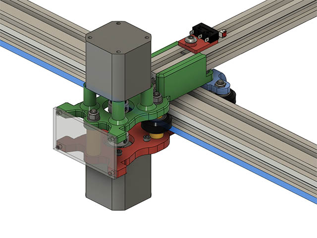
I went ahead & made adjustments to put a PCB board on the back of these motor plates. The translucent back plate is just a place holder until I know the size of the board I will use.
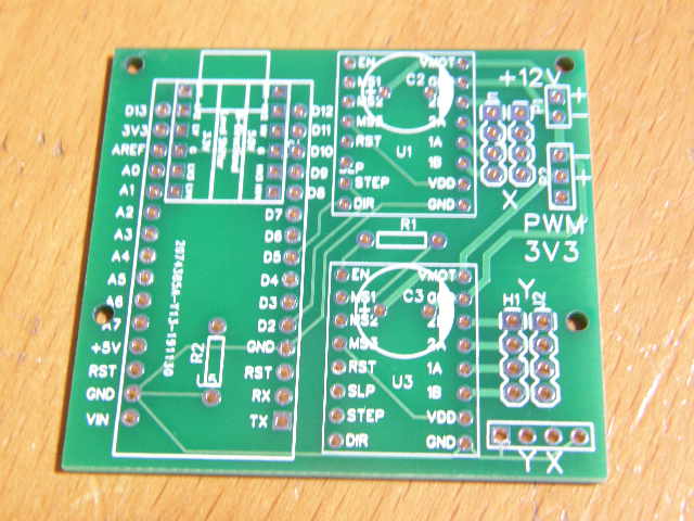
I designed my own pcb layout for my laser m/c, I wanted it to be as small as possible to fit on the back of the carriage. It holds a Nano, two drv8825’s and a 5 to 3v3 level shifter for the 3v3 PWM output to the laser. The eleksmaker will do the job fine but if you fancy a go at building your own I have spare PCB’s for the cost of the postage.
The focus on the laser depends on the optics that have been fitted, mine focuses down to about 3cm from the end of the lens before the lens falls off the end of the thread
Not a biggie if your 7W wont go that close, you will just need thicker feet!
Thanks for the offer. Since they are all thru hole soldering, I should be able to solder that. Not sure I want to go this way, but what would be shipping from your location to western North Carolina, USA & what other parts would I need for that board?
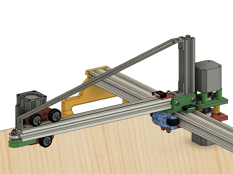
I have been pondering this idea of putting the belt above the 2020 cantilever like I did on my rolling plotter & looks like this might help give more support to the cantilever. I had used 2040 on the rolling plotter, so had to modify it to fit this design. I have the 2020 extended another 32mm beyond where it was originally. With the belt above this & if I can tension the belt to a good tightness, but not too tight seems like the belt will help hold a longer section of V-slot up. I only added enough hardware to the design to get an idea of what it would look like. I am showing a 500mm length of 2040 & 2020 in this screen shot. What do you think?
Best I can see the postage would be €1.40…say $1.60
Arduino Nano
2off 2k2 resistors
2off 100uf 16v electrolytic caps
1off quad bi-directional 5 to 3v3 level shifter (https://www.aliexpress.com/item/1972789887.html)
2off DRV8825 or A4988’s
pin headers and sockets
2p
I don’t think the rigidity of the cantilever arm is an issue. The main area of concern will be the X/Y joint…the wheels. Any play there will introduce unwanted movement in the laser head. The cantilever arm wont bend and your idea, as far as I can see, will only introduce belt tracking problems as you attempt to tighten the belt… I think you are over-thinking it again :-). If you want to counter the weight of the arm then increase the weight or moment of the counterbalance .
/2p
Very cool project, congrats! Looks much more solid than your typical aliexpress jobs.
My experience with this style of cnc moving bits (drawbot) is that the motors jerk and you get wobble and height issues from the in and out ends, ends up behaving a bit like a fishing rod at higher speeds. May not matter depending on how flat your target is or how accurate you need it. Good idea bolting the base down, pretty much a requirement. I had a bit of luck laying a rock on the top to increase the mass, less wobble, but it slows things down.
Might want to do some software to compensate for the height difference in the near and far planes, and the pendulum effect going sideways, there is always that little bit of slack that lets it jerk. If you are using GRBL, use the setting to keep the steppers engaged, helps a little bit.
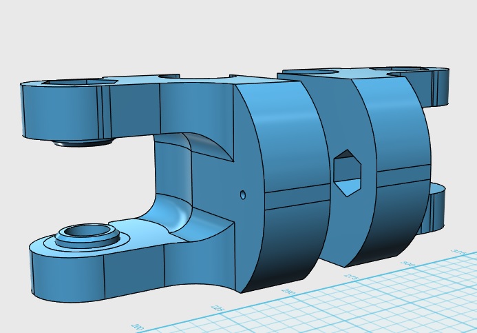
Thanks for the further info & will keep that in mind, but think I will still stay with a purchased board option. I probably won’t start ordering parts for another month unless something goes on sale. I see what you mean about the belt might cause a problem this way. I do currently have it 6mm off center in order to clear the laser carriage wheel bolts. On the other hand it has around 94mm overlap from the front side of the 2040 whereas it was 45mm before. The motor is also set back about 12mm further than the bottom motor. As long as I can get that cantilever beam squared up well seems like this could make the design a better balance. I will leave this idea alone for now & move onto some other parts I have not worked out yet & see if anyone else has some concerns about this method. Looks like I really don’t need to use end stops, but will keep them in the design for future use. Here is an end view of the cantilever beltway showing the offset better.