Hey Dave, festool sells replacement foam strips for the bottom of their track saw tracks. Some of that on the bottom of the beam, then fill the extrusion with led shot should give it enough friction to not move.
1 Like
That is a good idea, although if I put something under the beam the height of wheel offsets would need to change. I probably need to change them to slot holes anyway to make them more adjustable. The current version measuring with digital calipers is maybe 0.5 - 1mm height difference, but is hard to get an exact measurement placing the caliper on their by hand.
Instead of adding the wheel – why not move the motors further out to have a larger counter-balance effect?
2 Likes
I had thought about that a while back, but wanted to keep the foot print as small as possible & the way the electronics was mounted interfere with going to far back. Looking at it again, that would be worth exploring again. I should be able to change the electronics plate to be more horizontal than vertical. Since the top motor is separate, I could get a longer 2020 & extend that further back. Thanks for bringing that up. I have a 1 meter long 2020 I can test. I have a 500mm length on there now & probably 600mm would do it. I could probably move the electronics to mount on both sides of the 2020 where it connects to the top plate. Looks like a rainy day tomorrow, so might test that.
Keep going with the upgrades Dave…you will soon arrive at a Banggood laser engraver 
1 Like
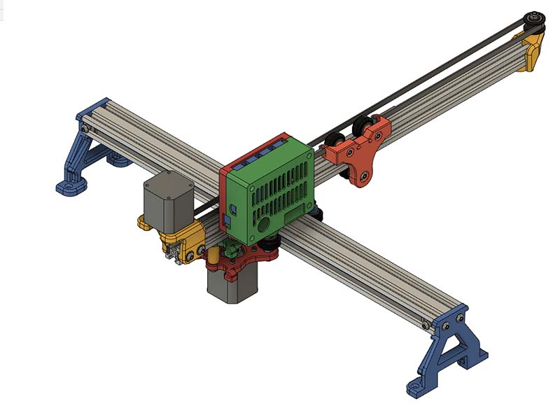
Dave was kind enough to share his designs and I tweaked them a little to make a smaller version of his engraver. The working area is only about 8"x8" (using 300mm extrusions from zyltech) but it is more than enough for my needs. I would be happy to share the files with anyone that wants them.
I made most of the parts thinner for lighter weight and changed the Y carriage to a more traditional eccentric nut design. My goal was to mount the Y stepper motor on the side to reduce weight, but I just could not come up with anything clean so it ended up back on the carriage.
3 Likes
Now that you can get those eccentrics from zyltech for $0.95 each, that is a good option. Think I had one version using those, but opted for @dart1280 method in the end. Are you still using another pair of eccentrics on one side of the back side to be able to adjust for 90 degrees or do you have that problem?
You should add your design as a remix on thingiverse. Please use the same license I used.
I bought some eccentrics from openbuilds and more from Amazon. I don’t really see any difference in quality. I have an eccentric on both he the inside wheels (where you had the big adjusters). I don’t know if I have any problem with alignment yet because I just did my first burn today. If that happens and I can’t adjust it out, I may need to change the design. I am fairly confident that even if it is a little off, over such short distances it won’t be noticeable.
I will drop it on thingiverse as soon as I can get the files organized and tweak a few final items.
1 Like
I created an openscad script for a parametric enclosure modeled after Openbuilds new Enclosures. I also included a spreadsheet for quick calcs. I asked them if it was ok before I uploaded it to thingiverse. I will probably make a different size than the standards & I might remix this to use T-Slot that Misumi sells so I can get them to cut it to correct lengths. Will compare costs first. I plan to triple the use of this enclosure to use on my Sphinx CNC, laser Engraver & miter saw (for cutting aluminum).
I have some spare 2020 and I’m trying to figure out what to do with it. I might actually make something like this to enclose my grid bot. I haven’t ever had an enclosed printer before, but this can get pretty noisy when it moves fast. It already has a 2020 frame, but I might still just duplicate it to make it more simple.
1 Like
You might be able to use 3d printed plastic cube for the corners. I included the STL file for one. You would just have to tap the 2020 ends. I included an option in the openscad script for those.
1 Like
I am adding the option for using misumi T-Slot & blind corners. Those blind corners save $40-$50 in hardware costs. Looks like they will work with V-slot, but cost wise getting the misumi cut to proper lengths is easier & less expensive than the V-Slot. Zyltech has door hinges for $1.95 each. I will probably get them from there ($6.01 from misumi). I am waiting on an answer from zyltech on the hole spacing of their hinges before updating my openscad script on thingiverse. Openbuilds hinge spacing measures 20.4mm in their 3d model & Misumi shows 21mm for their spacing. Here is a video showing how those blind corners work. Just need to drill an allen wrench access hole 10mm from the end of where the blind joints are.

2 Likes
here you go:
just search for VIGOTEC VG-L7X 20W Laser Engraver CNC Router Desktop on BG!
That or a similar one is what Mike was referring to. If you look at his build log that is linked at beginning of this thread, he copied his design from one of the Chinese versions & my version is a remix of his.
I was surprised at how many people have downloaded this design from thingiverse, over 1500 downloads in a month.
Ah, I see, I missed that.
I also pickes it up to my collection on thingiverse. I really like the design, I need to check this thread again and see if it worth it.  On thingi there wasn’t that much comment, especially the to the number of download.
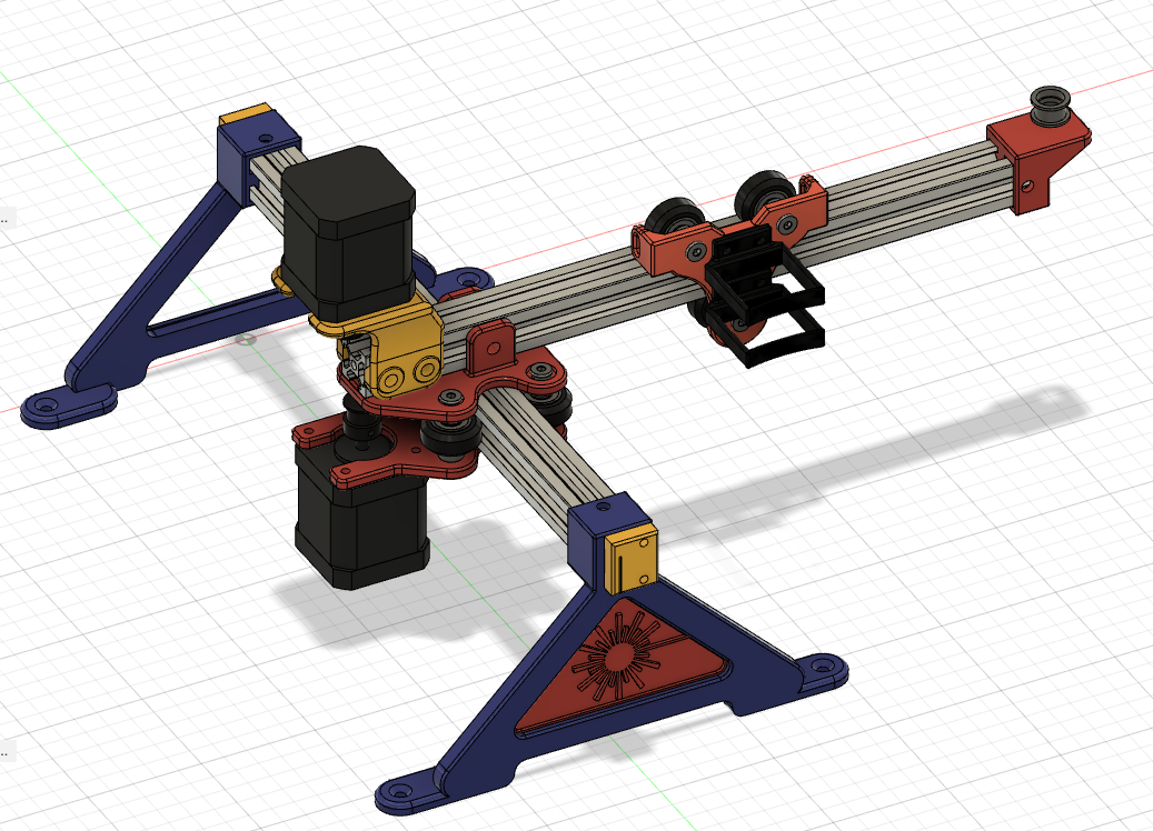
I ordered a 600mm length of 2020 from Zyltech & think I am going to move the top motor back some to give more offset weight for the cantilever @cwford got me thinking about this again. My main concern was adding more depth to the foot print, but think I can live with the extra 80mm coming off the back. I will just have to reposition the electronics. I don’t really need to redesign the upper or lower plates as that back center screw hole I can use a T-nut on the top to go in the 2020 instead of having a regular locknut on there.
Hi Mike,
could you share this PCB design?
Thank you,
Peter
Sure…
2 stepper laser controller.zip (21.9 KB)
or
here is a slightly re-vamped version…both operationally the same, just slightly different component placings.
I use JLCPCB for my pcbs and would recommend them…
1 Like
Thank you!!!
I am finally getting back to this design. Since @dkj4linux has not had any problems running his laser at 5v PWM, I am going to go ahead & use the Eleksmaker 3-axis Mana V5.2 board I have. I have been playing with shifting the 2020 further back for better weight balance & it does seem a lot better. I currently have it using a 500mm 2020, but have a 600mm that should be here shortly. I placed the 2020 so I could have about 10" burning width. I have the end of the 2020 placed 128mm behind the 2040. I designed a case for the Eleksmaker board to mount on the side of the 2020. I printed the base mount & seems a good fit, so am now printing the top cover. I will make another mount for Raspberry Pi to mount on other side. Here is what the 1st version of this design looks like. The motor connections are on top. The power connection & USB connection are to the back. Laser & endstop connections are in front. I probably should have put some vents on that top side. Will see how hot the drivers get like it is. I am probably going to use DRV8825 drivers.
1 Like