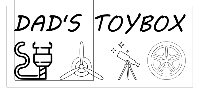
I am working on the design of my second project, which is going to be a carved sign. I’ve found and tweaked some photos (converted from raster to vector in Inkscape, then DXF.
My question is, I am current going through hoops to convert them to single line. The way inkscape works, is it makes a vector line on either side of the black line in a jpeg photo (however thick the line might be).
So when I go to make the toolpath (I am using F360), it wants to cut on either side of the original line in the art. I havent found an automated way to make a centerline.
My plan was to use a single line toolpath, and have the width of the resulting carve be determined by the angle of the V-bit, and the depth of cut.
I suppose the alternative is to CAM it more like a pocketing operation to have the bit run in between the edges?
I’ve had the same problem as you. The solution I’ve found working in my case is the plugin “Centerline Trace” for Inkscape. It does simply that. It traces lines in images and converts them to single line vectors. Works like a charm. You have to remember to select the graphics before running the plugin. Other than that - pocketing between two vectors can also achive somehow similar results - but it doesn’t let you easily carve with a v-bit. Using the pocket function will also complicate things if the mill is wider than the pocketed area. A carve/engrave tool would follow the vector, no matter the width of the mill.
I installed Centerline Trace this morning, but I wasn’t happy with the result…Maybe I should try it on some of the other graphics in the layout and see if maybe it can cut some of my work down.
I don’t know about doing this in Fusion, but there is a free program called F-Engrave that will take the vector output from inkscape (with the 2 line “outline”) and generate the V-bit paths necessary to carve the image. No center line necessary, F-engrave will vary the depth of cut as needed to vary the cut width.
Fusion 360 has an engrave operation, but I havent been able to get it to generate a toolpath as of yet, so I have been working with the Trace operation instead as I was more comfortable with it. Perhaps I need to dedicate some more time to figuring out the F360 engrave.
So, the only problem I was having with the Engrave operation was that only one type of tool is valid for this operation, and I hadnt found it yet.
Now, it does machine the centerline of any closed contour, just as I want. However, it dynamically adjusts depth to machine UP TO the boundaries of the closed vector. Because I pieced my artwork together from multiple sources, the line widths are not of a uniform thickness.
My choices are: 1) make my own centerlines for a trace tool path 2) make sure my artwork is of a uniform and desired line thickness. Not sure which is less work yet.
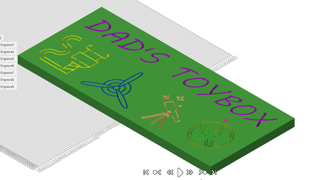
Editing this post again. I think I have this licked. You can use the engrave operation and vary the depth by making the top height equal to the contour, then applying an offset to the top height. Negative for a thicker line, positive for thinner. This is what my simulation gives me:
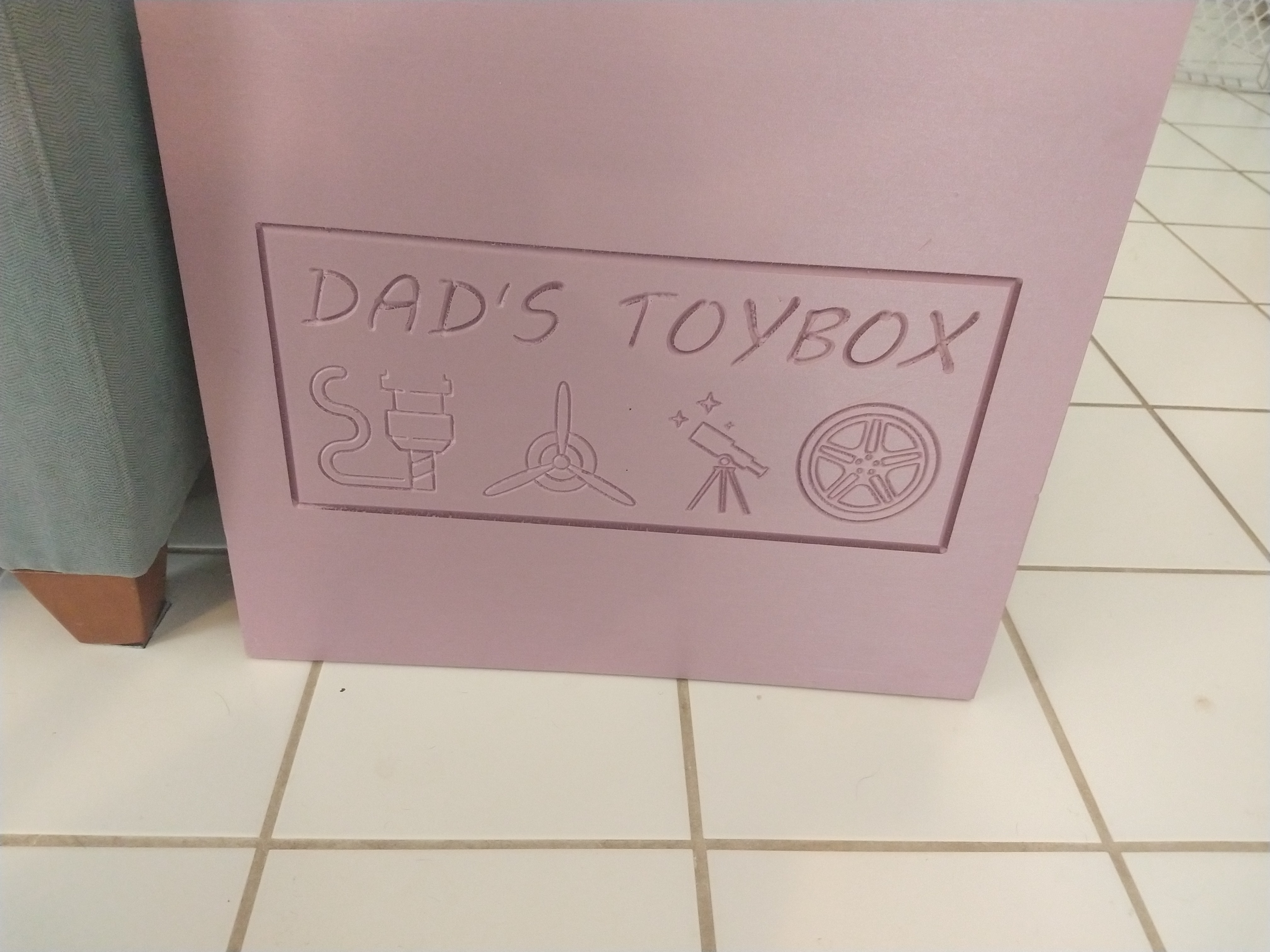
Bear in mind that there is a vector on every edge. All of the “brush strokes” are a closed contour, regardless of thickness. I was able to get the resulting CAM to create a centered toolpath, at a depth of my choosing for each. They arent going to be perfectly equal thicknesses, but close enough for me I think.
Sorry I was so spastic with updating the thread, but I thought maybe someone in the future might find this useful.
I’m pretty new to this, but I thought the normal way to do carving was to use the outline, and get Estlcam to calculate the centre line and depth based on the angle of the bit?
My goal is to have carvings of a fairly uniform depth and width without having to calculate the centerline myself, and without having to normalize the width of the vector paths in the artwork. In other words, I’m looking for shortcuts, lol.
Ah, I see - I think inkscape’s ‘Path / Dynamic Inset’ might be just what you need.
That menu option takes a path and turns it into an object with a handle at the top. Drag that handle around to change the line width. Turn the object back into a path when you’re done.
I’ve come to realise that a significant part of this hobby is reading inkscape (and OnShape) instructions
Estlcam can engrave along the center of a line. I don’t know how it will interpret these paths, unless you convert that thick line to a single line though.
I was using it for text and it needed a fair bit of cleanup afterward. I think it was mostly the junctions between multiple lines where the “true” centerline is ambiguous, but if your artwork doesn’t have too many junctions then it might work well. Just google “centerline tracing” for more information.
If you want it to end up with the same thickness as it originally was, then why not just export it as is, and do a carve with estlcam? It will select a depth based on the width and the angle of your bit.
My goal was the opposite. I wanted uniform thickness of all line in the final carve, regardless of the thickness in the artwork. I think I’ve gotten close enough to that goal.
Apologies for picking up on an old thread but I’ve been trying to do the same thing.
How did you get a tool path that follows a centreline of the closed contours? When i use engrave (or trace) i can only get a toolpath around the edges of the vector lines. Any help you could offer would be really gratefully received!
I do indeed use the F360 engrave function. I’ve made many signs with it since this post. You just have to make sure you use the proper geometry engraving tool with this tool path type. It will follow the centerline, while also automatically adjusting depth to keep the cutter always within the closed boundary of the artwork.