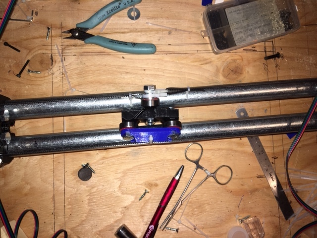
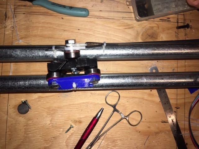
Hi, I finally got all the pieces I needed to start building, and with the exception of a few hiccups things are going pretty good. Except my centre piece has never sat snug between the two rails. I had hoped that when the belt was attached and tightened that that might make it fit better, nope! As you can see in the pictures by pushing on the top or the bottom of the piece I can get the bearings to lift off the rail by more than a mm. Which is enough that you can twist the piece between the rails.
I have checked it every way I can think of. Im using standard 3/4" EMT (23.5mm OD), which fits nice and snug in the rollers. I thought maybe my printer was messing the dimensions, so I imported the centre STL into fusion 360 and made some measurements. My print matched those dead on. Dan in the Your Builds topic Build PLOG. ZenXY LACK hack end table posted a video to youtube that looks identical to my problem. https://www.youtube.com/watch?v=0frCRqq0uRI
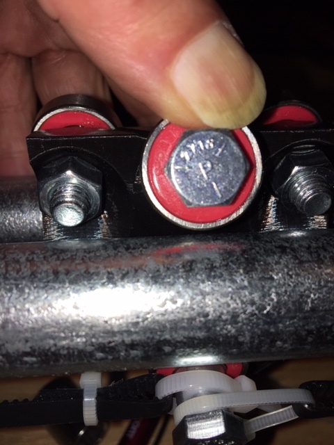
In my case, the center piece fit snugly when first installed, it became loose because in the course of movement and some stuttering it ended up hammering the bolt threads into the plastic, and altering the angle it was holding the bearings to the tube.
It does look like the same result which I can say with certainty is not usable.
Did you print parts for the 23.5mm tube?
Did you check that your tubes are really 23.5mm OD?
Are you using the correct size bolts? Are they snug in the holes? I could not just push the bolts through the holes, I had to thread them through, but they could move when tightened.
Mine was made using the 25.4mm (1") diameter tube, and I had some other issues that I have since corrected, so I can’t speak as to the center fit with the 23.5mm version.
Dan,
Thanks for the ideas. The parts are for a 23.5mm tube, the tube is 23.5mm (measured with a digital caliper), the bolts slide in smoothly but fit snug, my 608 bearings are 22 +/- .1mm. Everything I have measured has the right dimensions as far as I can tell. It occurred to me that maybe my rails were bowed giving a bigger gap in the middle, but the same looseness occurs when the centre piece is moved over right against either side roller.
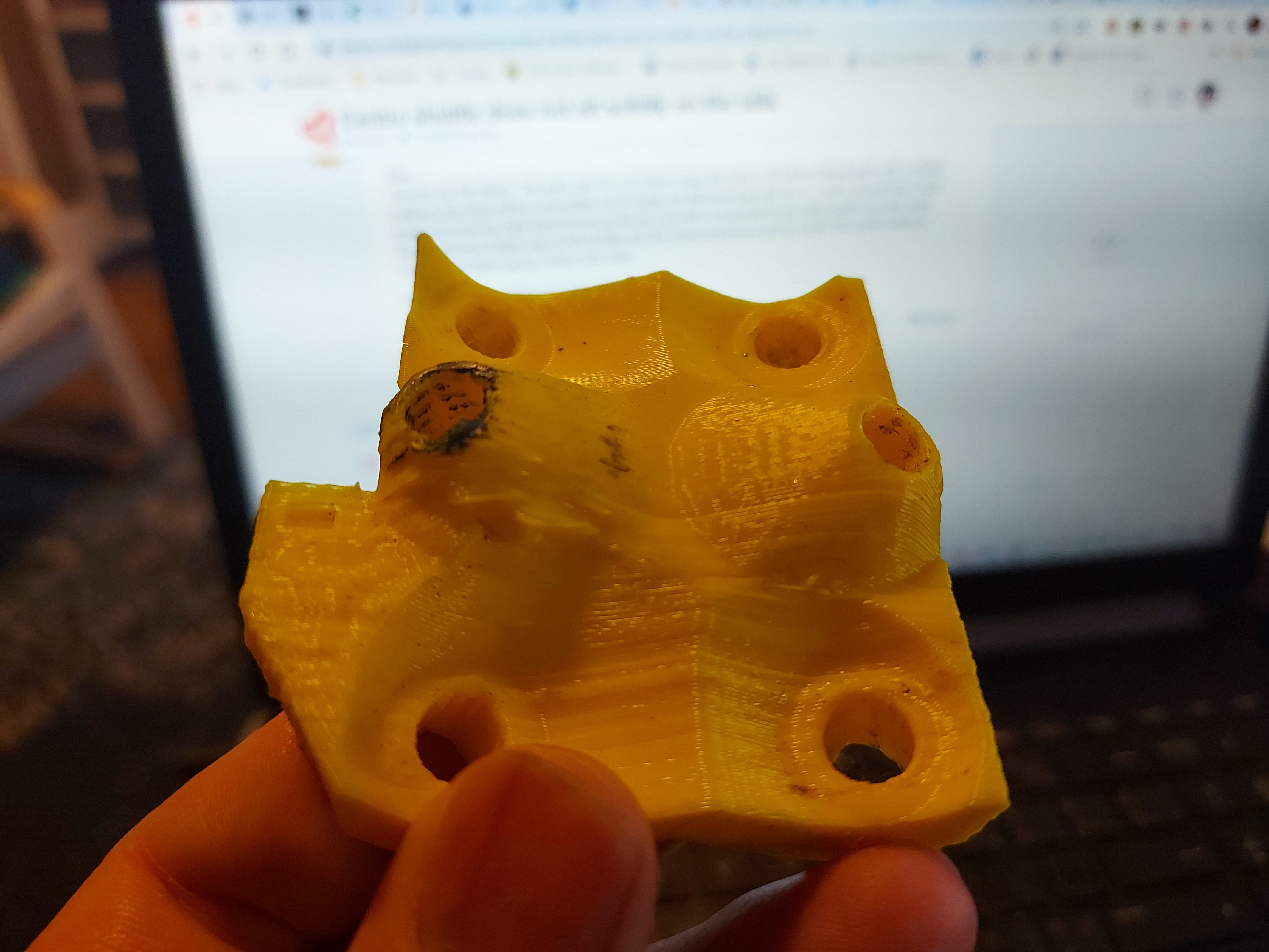
The amount of slack required to make the shuttle really loose is tiny. In this picture, you can see where the threads indented the plastic because there was a little grease in there. In the black shuttle from the video, you can’t see it at all. Only the one is affected that I can see and it’s the difference between tight and the wiggle room you see in the video. You can barely feel those dents with a sharp dental pick. If your bolts slide in, that might be enough.
I was thinking of ways to prevent that. One was to heat the bolts and melt plastic into the threads where it will be inside the piece, but I haven’t tried that yet.
YAHOO! It’s fixed.
I bit the bullet and with Fusion 360 reduced the angle between the x-plane and the axis of the bolt that the belts get attached to, by 5 degrees. That had the effect of moving the contact point of top bearing 0.7mm closer to the rail, which was enough that everything now is secure.
Thanks for all your help Dan.
Now it’s onto tesing the firmware. My original ender3 board has been sitting around gathering dust since I replaced it with a SKR mini e3, so I though why not put it to good use. I took the latest marlin for the ender3, modified the settings based on the settings for the ramps board in Ryan’s github repository as well as I removed the display code, since I am going to use octopi to control things for now,. X and Y motion works’ the only thing I still need to figure out is the end stops, they don’t seem to be working, probably need to be inverted.
I am sure somewhere I have made an assumption that going to bite me, but 2 steps forward , 1 back still gets me there.