Because I use or plan to use so many different tools with my MPCNC, I want to have the electrical connections be as easy as the quick release mount I’m using. To this end, I plan have two RJ45s mounted on the Z tower - one for the Z stepper and touch plate connections, and one for an extruder stepper, thermistor, and heatsink cooling fan. A third connector, which will probably be a 4 pin molex, will carry higher current to the hot end heater and cooling fan/laser.
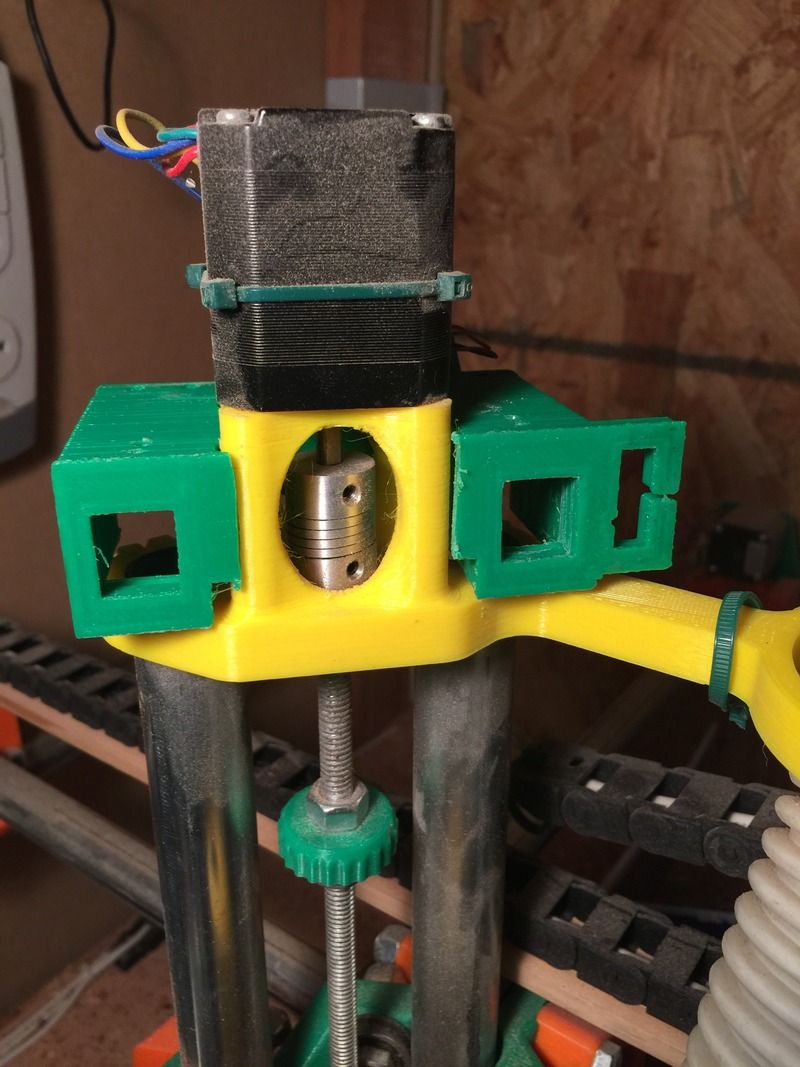
To this end, I designed a mount that clips on to the Z motor mount and provides mounting points for those three connectors. It also has eight screw terminal points on the back, to provide even more versatility for connections. There are also lots of holes all over for cable routing using bundle ties.
Even if you don’t plan to quick-change your tools, you might find a use for something like this, so I put it up on thingiverse, http://www.thingiverse.com/thing:1273861.
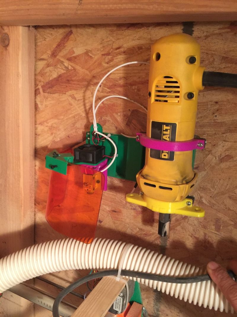
This picture is of a prototype, but the design is the same. I’m just experimenting with the sizes for the keystone opening now.
@nerdyrcdriver - no, I don’t think cat5 or 6 could handle the heater current. I will use a cable with higher gauge wires and connect through the 4 pin molex connector for both the extruder heater and the laser (driven by cooling fan power).
Alright. Just standard PC 4 pin molex like dvd drive and hard drives use? Or one of their other connectors? Just curious since I have found a few good connectors asking about stuff like this.
@nerdyrcdriver The 4 pin molex is just what came to mind as a quick disconnect that could handle the higher current, but I would either have to splice the end onto the cable, or buy a connector kit, which requires an expensive crimper that can be difficult to master. Like you, I’ve been keeping my eyes open for a better option. In another thread, Leo69 mentioned 4 pin xlr connectors. After some research, I’ve ordered these: http://www.amazon.com/gp/product/B015K3Z6CS?psc=1&redirect=true&ref_=oh_aui_detailpage_o00_s00. 10 sets for only $17, and they’re solder rather than crimp, which is better for me.
Those look like pretty nice connectors. I love using ones that screw together like that. They look pretty easy to solder too. I have to use special crimp connectors at work sometimes and they do require quite a bit of practice to get right.
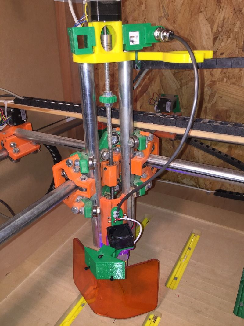
Here’s an update on my connections mount and some other stuff. I finally got my 4 pin XLRs in, so I put one on the connections mount. I had already printed one out with a place for a molex connector, so I made an adapter that clipped into the molex slot and held the XLR connector instead. I also installed an RJ45 plug for connecting an extruder head.
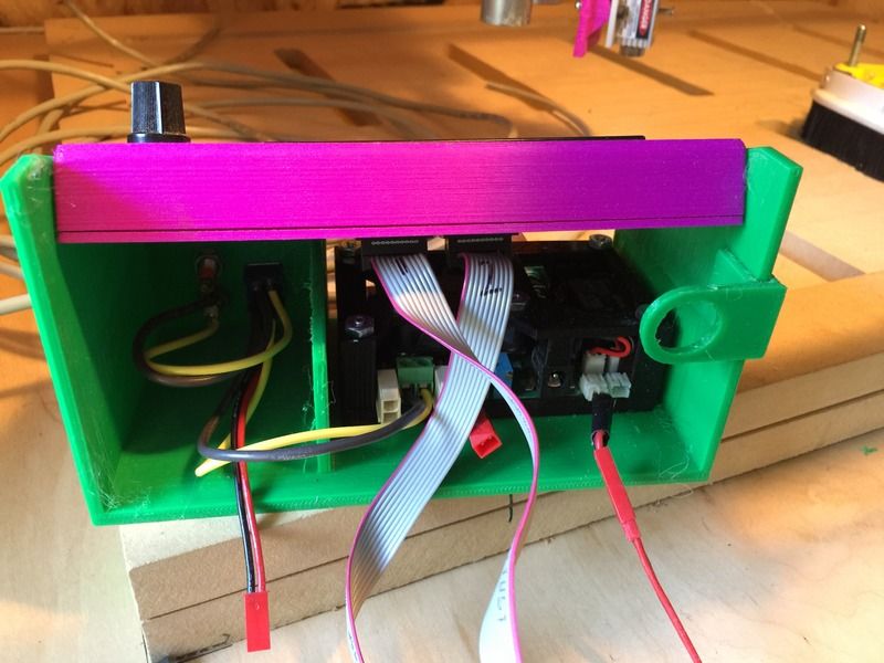
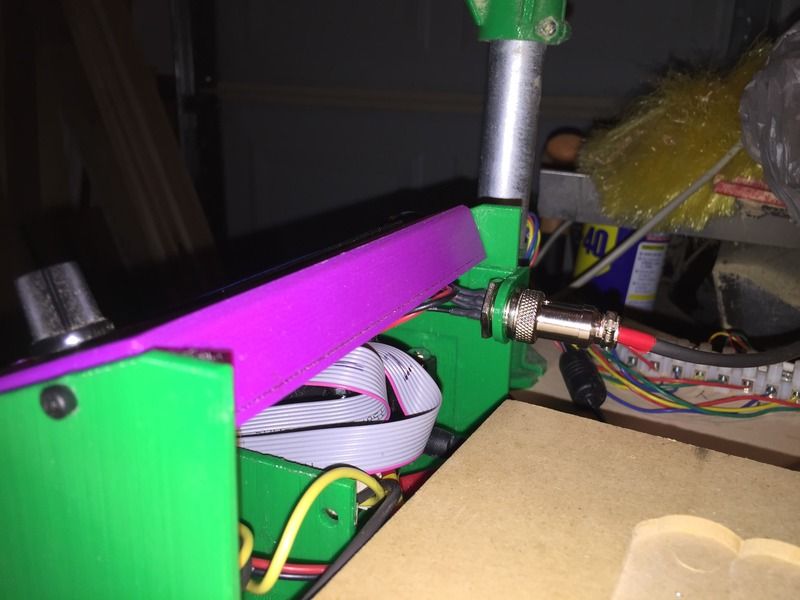
I added an XLR plug to the laser, and also made a simple laser shield holder that clips on the laser mount. I ran an 18-4 cable from the XLR on the tower down to the control panel. I created a box to hold my LCD and laser driver. I kept the LCD in the same case I’ve been using, just removed the legs and mounted it in the new box. The new box is not fancy, but it does keep things nice and neat.
The laser output goes to a DPDT switch. If the switch is up, the output is routed to the laser. If the switch is down, the output is routed to two test jacks, to make it easy to connect a multimeter to set the driver output. The control box connects to the laser XLR plug, and to the ramps box (for the laser signals) through a JST plug.
Love this design. it makes tool changes so much easier. ive got mine setup so if I need to I can remove the entire z-axis without screwing up my wiring
Nice, clean, versatile. Great job guys. I have a 4-pin XLR on my laser also and I just ordered a 12-pin XLR connector to create something similar for an extruder set-up. I also ordered some cable sheath since I can’t find a suitable cable to use and I’ll probably have to make my own. Anyone have any ideas? I figure I can use all 12-pins on the connector (4 for extruder motor, 2 for hot end, 2 for thermistor, 2 for fan, and 2 for proximity probe) . The problem is that the hot end has higher wire thickness requirements than the other connections so I’m pretty sure I’ll have to make my own 12-conductor cable. Unless there’s something already available that I don’t know about?
Very nicely done. I am working on the same thing right now, can’t wait to get rid of the wire mess that is assembly and testing. I decided to build a small scale version in my office and get everything working like I want before I scale it up for the shop and get all the wiring tidy. Let us know if you share any of these on Thingiverse. Nice job.
AHHHHHHHH OCD overload, fix those wires!!! giving me a panic attack. I have a wire obsession. I spend way to much time on wires usually.
Really though if it works leave it. When I was testing the first one, the first few rebuilds I resoldered the wires every single time, then came the solderless mounts, then the wiring harness. Now is takes an hour or so to do what used to take a full day.
lol.i did a decent job on my laser but my ramps and stepper drivers are a mess. I doubt my machine will ever look a clean as some of the setups I’ve seen here but I’m content.I still want a clean set up for an extruder because i know that will not survive I dusty router environment so it’ll need to be easy to attach and remove.
LOL, trust me, it drives me nuts. I had already designed a table and all the other stuff to build first but decided to take the time to get everything the way I want it and then refine and make it pretty. I have all the parts on order to make all the connections with RJ45’s, cat5 and 12 pin molex connectors once I am happy with how it works. The way I see it, the motion is the important part. After that it is just what tool I hang on it. Can’t wait to add some of those too!