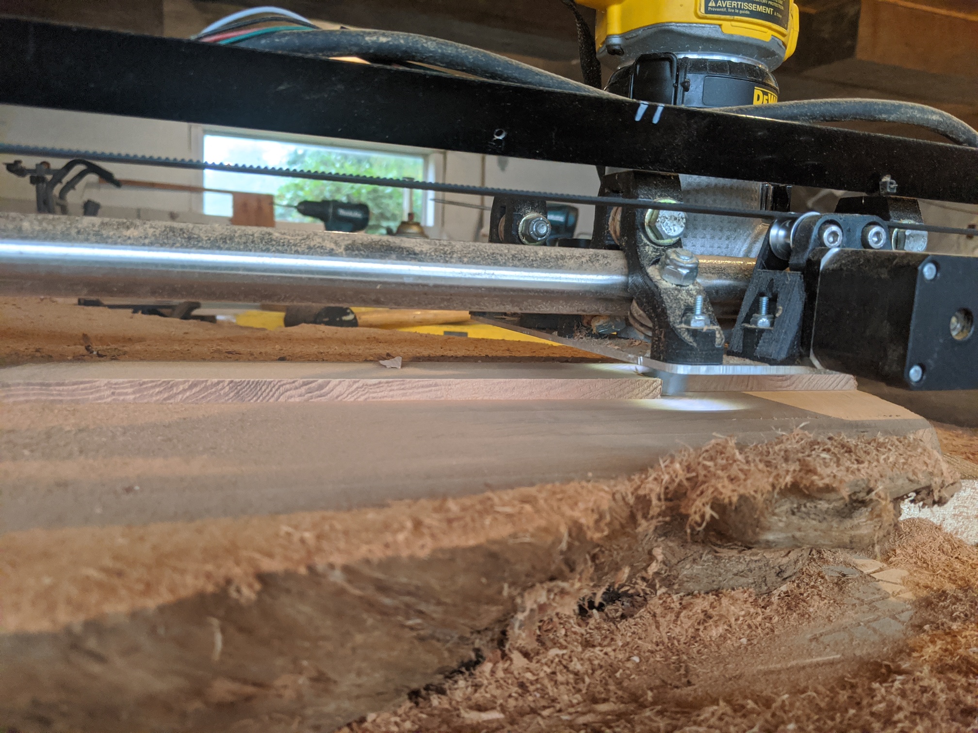
Took a bit to figure it all out and it is only cedar but I got a variety to do and this needed 21/2" removed from bad chainsaw work lol. By the end it was hogging at 12mm doc 1000mm/min and router on 1 or 1.5 with 1" facing bit
10 Likes
Woe! That’s some serious stock removal. 
Nom nom nom. That is possibly the highest volume of wood removed per second I’ve seen on a v1 machine.
i would really like to figure out how to get M106 and M107 into the post, right now i have to edit it every time… any ideas?
What are you trying to do, M106 S0-255 should work.
You can always add some custom code that you want to run at the start and end of code post from f360. Let me know if you need instructions.
Awesome projects!
Man I keep coming back to this. I am stupidly impressed. I honestly did not think the machine was capable of this type of material removal rate. The scalloping could be a few things but with that sort of hogging out nothing would be perfect, a finishing pass could clean that right up I assume.
Now I want to see if I can get similar results. Like, am I still not pushing it hard enough… Thanks again for sharing this (and boosting my confidence).
2 Likes
Contrary to what most think bigs bits have mass and more spinning mass = more stability. The first vids were red cedar, very soft. The sticky dense Fir burls I cut at 2200mm/min 4mm doc 23mm step over. I’m done with 1/8 bits. They plug up, don’t clear and the heat dissipation is terrible. I actually stalled the router with that 1" bit going to hard. I have learned to never b afraid to push with anything new. Also I tell u what I do, lift the router up in it base, find the speed needed to produce proper chips and sound. Then manually run the router down untill u find the sweet spot between load and reliability. I have been building your machines sense the start. I think the first one was in 2015… I have alot of hours of r and d in now. From CNC plasma to milling steel. Started with a 3d printer and built my way up to what I believe in an industrial CNC plasma cutter… And really the super light design on the low rider with 36v power provides a machine that I think performs awesome. Only issue I have had with your designs is on my plasma… It eats the plastic parts up but I am in the middle of a redesign…
2 Likes
Also the scalloping is inevitable, specially with this machine in my opinion. There is very little to keep the tool level in the y axis. I cut my passes is the Y for that reason even though it creates issues with the material building up under the rollers. If the the x direction there is visible steps…
2 Likes
Jealousy is setting in… nice work…
How did you digitize the shape of the slabs?
Interesting, love knowing you have tried a bunch of my machines and know the evolution. Very valuable to me.
I also do a lot of test cuts to get a feel for new material and I just got a second load of 1/4" endmills. I still think it is good for newcomers to start with 1/8", cheap and low cutting forces, but I am starting to feel like 1/4" might actually be a bit easier. More testing to do I suppose.
Your scalloping, you feel your machine is less rigid in the direction of the rails (the way your scalloping is) vs the other way. I have always felt the other way is by far the weaker of the two. As in I can twist the router in the table axis direction pretty easily, the rail direction has always seemed solid. I ask because you probably have far more hours on it than me.
Shhhh
And you know I am always looking to improve and release a new toy!
2 Likes
I think iean the same thing.The x direction is much more rigid, in keeping the tool square that is. In the y direction, one tube flexes up and the other down which in turn brings the tool out of square. Either spreading the tubes in the y direction or increasing there diameter helps this… Correct?
1 Like
Also don’t forget the direction of the load on the tool is not the same as the direction the tool is moving. Especially with high stepover, I might expect cutting in Y to have loads primarily in X that are better supported mechanically.
Machining in the x leaves steps with a 1 inch bit… makes sense I think… The larger the bit the more u see if the tool isn’t perfectly square… Even the large 30k 5*10 router table I have access too does this to some extent…
And my work flow is as follows: take picture square to table with material secured and load into fusion, scale picture, trace and extrude body then manufacture
1 Like
Yes, I’d love to figure this out…
I started out with 1/4" bits with good results and tried 1/8" bits to cut some finger joints for some serving trays. They were terrible compared to the 1/4" bits. Variation in cuts was related to direction, load, and speeds. I found the deflection to be way too much for anything except very thin materials (cutting map profiles, etc.). So, I’ve redesigned everything for 1/4" bits.
1 Like
so if you edit your post processor in F360 look for the property “Extern: Start File” and “Extern: Stop File”. I then added 2 files into my export folder named “SpindleOn” and “SpindleOff” with whatever Gcode I want to start and stop with. I then add these files into the start and stop file properties and whatever gcode is post processed into the folder will have the extra lines you added.
please let me know if this doesnt make sense