It’s my first time using CNCjs. I’ve connected the CNC xPro V5 by USB to Mac. Connected though port which showed after connecting the cable.
The problems which I have are similar to the topic:
first-runs-with-my-cnc-cncjs-not-cooperating/31361/4
but with some differences.
The problem I have:
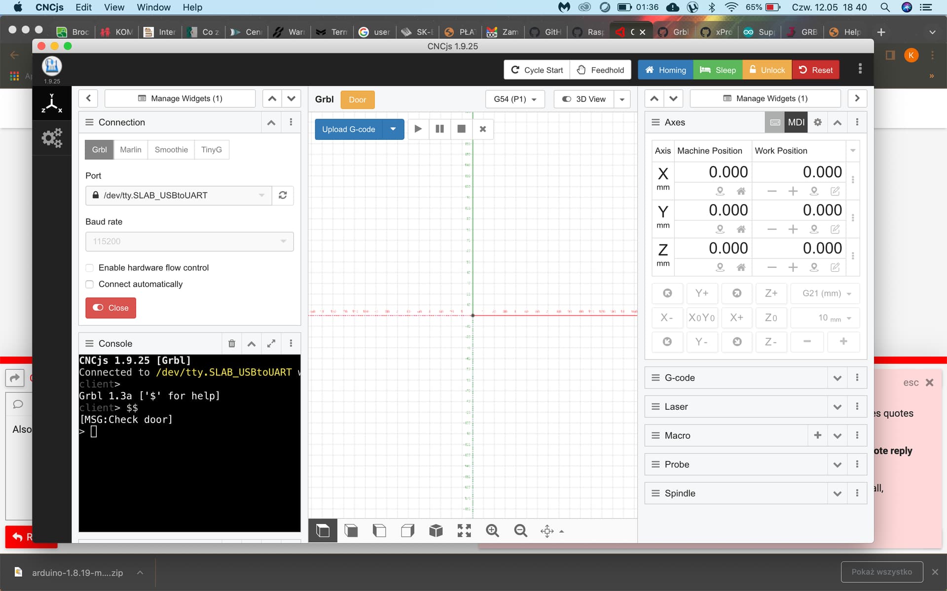
axis control is locked (grey) and cannot control it,
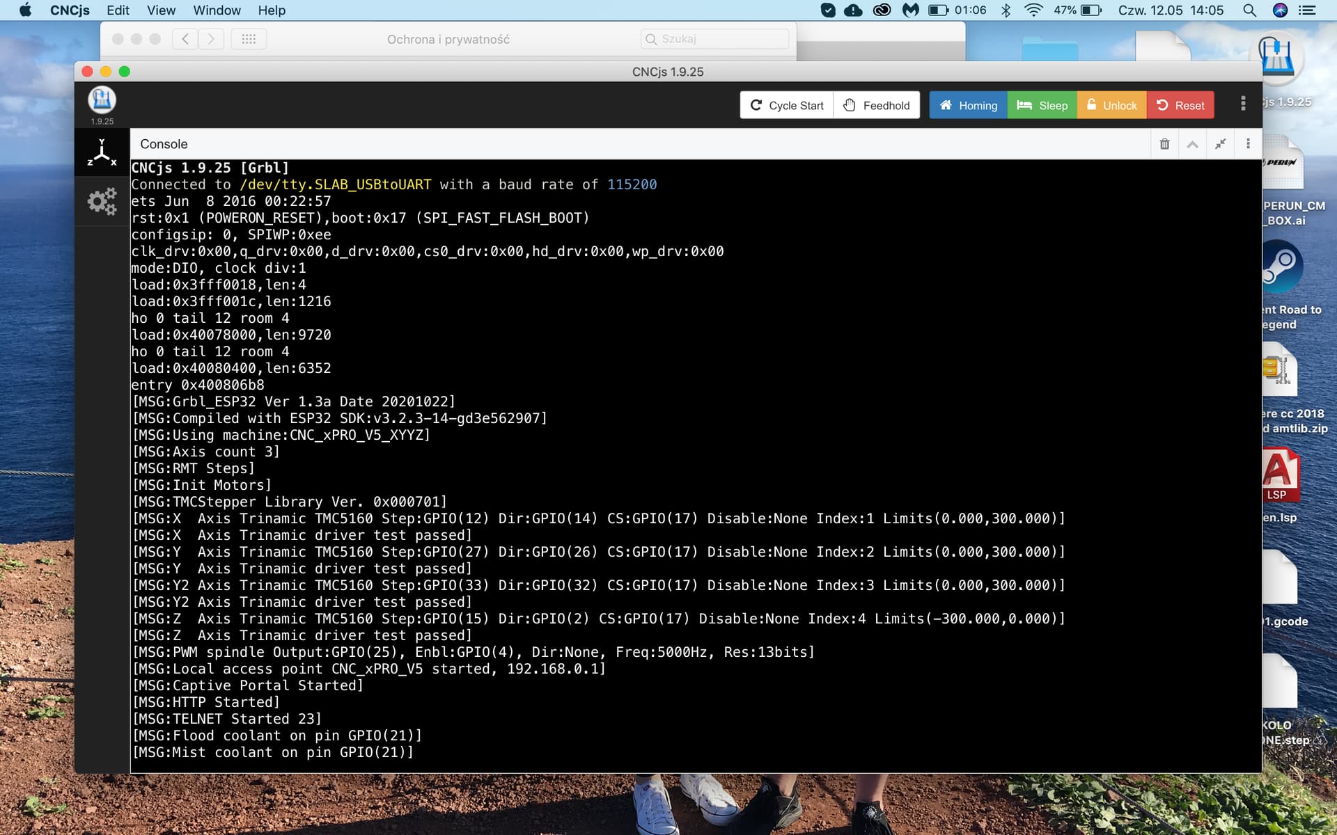
when connecting without “hardware flow control” I do not get “welcome” message from controler. The message only is send when “hardware flow control” is ticked.
when I connect with “hardware flow control” ticked and using Marlin insted GRBL the axis control is on, not grey but still cannot move anything.
I use baud rate 115200.
CNCjs version 1.9.25.
I attach the command screen, maybe someone who have any exprerience with CNCjs can help me.
Since you have an esp32, I suggest instead installing FluidNC firmware on it. It’s basically the most current GRBL for that chip, and you’ll likely find better support with it.
IDK, but it looks like the github for that controller has some different firmwares you could try. That last message about the door could indicate improper firmware, but IDK much more than that about the xProv5:
edit: WRT hardware flow control, that’s not something you see very often on these machines since they usually have very short wires and noise control circuitry (usually flow control is disabled in firmware).
Ok, So I know what is my first mistake - probably done something wrong with the wiring of the “Stop emergency button”. Right now after pushing the button I have control over the axis.
But after pushing the jog Y+ it changes the status from IDLE to RUN but the motors do not work.
There are some grbl users here. They will be a long at some point.
IIRC, the reset is normal for grbl if you have it configured for homing. Grbl doesn’t want to jog until you home the machine, and if you don’t, you can unlock it with the reset. That’s what I remember.
Hardware flow control is part of the serial port spec, but the USB serial converters don’t need it.
I will leave the solution to my problem for someone else who might struggle.
The problem was not with CNCjs. It’s with the configuration of the Hardware - CNC xPRO v5 controler.
You have right now few firmwares to choose - about 4 - You can find it on Github.
Spark-Concepts/xPro-V5/tree/main/Firmware
So generally you have to options of the safety switch:
NC - normally closed,
NO - normally open.
I couldn’t do the thing becase I didn’t know that the firmware loaded on the hardware was the NO - so the safety bytton needed to be pressed - if wasn’t machine would think that door are open.
In this case CNCjs is locked.
But I want to use this “emergency button” to kill the machine if something goes wrong while operating and to be able to use machine right from the start after opening CNCjs.
So after changing the firmware to NC type everything works as it should. (you do it after connecting to CNC xPRO v5 thought ACCESS POINT, wifi signal which controler is making on his own and update firmware through WebUI, password for connection is 12345678).
(Sorry if this sounds like a rant. This is a bit of a soapbox issue for me.)
Make sure that your e-stop configuration meets your needs and risk tolerance. Test it, and don’t trust assumptions about how things are supposed to behave. And, remember that you’ll be reaching for this when things aren’t going well - you’re likely to be flustered, frustrated, or just plain terrified.
I don’t trust the micro-switch “E-Stop” connections on these boards that just reset the microcontroller to protect me in case of a real emergency. Grbl supports cycle start, cycle pause, cycle cancel, and e-stop connections through the CNC Shield that I’m using. I wouldn’t trust any of them to truly stop all activity if the machine were misbehaving and/or creating a dangerous situation. I’ve got spindle control and other relay-controlled connections also connected to the microcontroller. These relays have Normally Open and Normally Closed connections, similar to the microswitches. If an item is connected to the Normally Closed side of the relay, resetting the microcontroller is going to turn that item back on. Not the behavior I want from an Emergency Stop.
My e-stop button (purchased from the V1 store) cuts the hot lead on inbound mains/AC power that feeds all aspects of the system (microcontroller, stepper power, AC relays, spindle control). I don’t currently have a laser on my MPCNC, but if I add one, its power will also be supplied downstream of the e-stop button. If I hit that, I have 100% confidence that there shouldn’t be power to anything (see, even there I’m hedging my statement, because in emergencies unexpected things can and do happen). This configuration meets my needs and risk tolerance.
I agree 100 % the only sure way to stop is to cut all power! In a emergency i am not worried about the project just what is happening that has you pushing the big red button
Best to keep it public on the forums, so others can benefit from being able to read through the troubleshooting process.
Velocity and acceleration can be tough to tune, since they interact and “failure” on either result in the same symptoms - lost steps. Since each build is different, wringing the optimal settings from your machine is going to depend on the machine’s ability to move, and your tolerance for having to start a job over if you push it too far.
On the first CNC I built many years ago using EMC on Linux (now called LinuxCNC), the commissioning process went in the following order:
Check axis direction, and either flip in software or flip the stepper connection so things move in the proper direction.
Calculate steps per mm for each axis and set that in the configuration tool. Do some tests at slow speeds to see if you’re at least in the right ballpark, but don’t adjust to measured results yet, stick with what the calculator says to begin with. Don’t worry too much about minor variations until you’ve tuned other aspects of the system.
Set acceleration based on experimentation. For this phase, pick a velocity slow enough that you’re guaranteed not to loose steps. Slowly increase acceleration and do test moves at that slow speed until you see/hear the missed steps, then decrease acceleration to 5-10% below the point at which step loss started.
Set velocity, also by experimentation. Now that you know acceleration won’t cause lost steps, you can increase the velocity settings and doing test moves until you lose steps. Once again, back it off to give yourself 5-10% margin of error, and your motion settings should be good.
Check dimensional accuracy. With steppers, lead screws, belts, and pulleys the calculated steps per mm should be 100% on the button. Any variation is due to “slop” in the system. A major source of that in the MPCNC universe is loose grub/set screws that attach pulleys to stepper motor shafts. Another less common source is belts that are a bit too loose, or steel reinforced belts (these are often white, where the fiber reinforced belts are black) where the constant tight radius bending of the belt around the pulley causes the reinforcing steel to fatigue and break. Fiber reinforced belts don’t seem to suffer this problem. Horizontal lead screws may need things like backlash compensation or anti-backlash sprung nuts, but on the MPCNC gravity is aligned to virtually eliminate backlash concerns on the Z axis, unless you have significant upward forces generated by your tool or cutting operation.
If your experience of 3D printers matches mine, the X, Y, and Z axes didn’t need motion fine-tuning. The mechanics of these are pretty solidly deterministic, so “the math just works.” The extruder needed careful measuring and tweaking due to variations in “bite” between the extruder drive gear and the filament with added variation from tension bolts and/or idler settings. This changes the effective diameter of the feed gear - i.e. the mechanics are variable in a way that belts, gears, and lead screws just aren’t. This is also why most slicers offer a method to “tweak” extrusion settings on a filament-by-filament basis (e.g. extrusion multiplier in Prusa Slicer. Since PLA is “harder” than PETG the extruder drive “teeth” don’t bite as deep, flexibles are even softer so teeth sink in even more.
I agree with you that reliable is better than fastest possible, especially in a home shop/hobbyist situation (which is where I am).
Sorry on a couple of levels. I don’t know that I’ll be of much help on the specifics of your machine as I have no experience with it. If you purchased it, is there support available from the vendor? They should have a good idea of the capabilities of the machine. The velocity and acceleration values should be very close, if not exactly the same, regardless of the software tools being used to drive it.
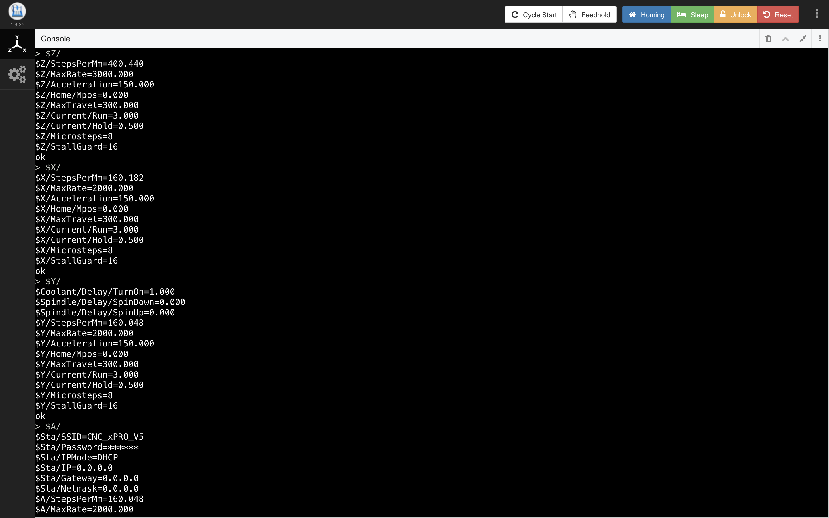
Where do the steps per mm numbers come from? Do you have imperial leads screws that cause the calculations to have decimal components? The belts and metric lead screws I’m used to tend to end up with round numbers for steps per mm.
In my (limited) personal experience, lead screws are slower than belts (unless you’ve got ball screws, which I’ve never actually implemented). 2000 and 3000 max rate seems quite high to me, but it’s not clear whether the units are mm per minute or mm per second. Also, you’ll eventually want to match your MaxTravel to the actual sizes of your axes, but that can wait until you’ve got things moving.
The control board I used with the nema23s on my old phlatprinter didn’t allow for current adjustment, so I don’t have experience tuning for those motors. As long as you’re within the current/amperage range for the motor (see the manufacturer’s data sheet) you shouldn’t be in danger of damaging them. If they’re getting too hot to touch you’re running the current too high. If the drivers get so hot they pause to protect themselves, you’re running them too high - but adding heat sinks and active cooling (a fan) can mitigate this. If things are mechanically well aligned, lubricated, and move smoothly but you still lose steps, you may want to increase current as long as you’re not hitting the “too high” markers identified above.
As far as the spindle is concerned, my advice is going to be even more generic. The spindle control I’ve used has been pretty basic - either relays for simple on/off, or the V1 PWM control solution which ran the PWM signal on the “Spindle Enable” pin on my shield. I know there are lots of options, including things being reversible, and safety interlocks, overheating protection, etc… I’d need to rely on the documentation for your spindle controller (VFD?) provided by the vendor. Here again, they would be the experts I’d turn to for support with their products.